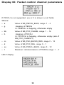
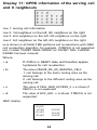
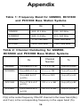
1
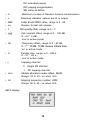
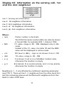
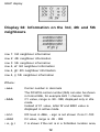
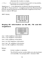
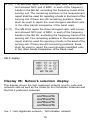
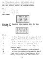
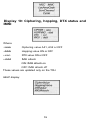
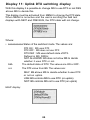
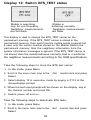
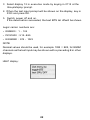
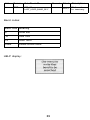
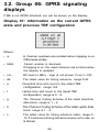
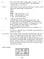
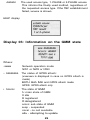
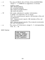
User Guide for
Network Monitoring
Menu
EGSM900
DCS1800
PCS1900
Copyright © Nokia Corporation 2002. All rights reserved.
Reproduction, transfer, distribution or storage of part or all of the contents
in this document in any form without the prior written permission of Nokia
is prohibited.
Nokia and Nokia Connecting People are registered trademarks of Nokia
Corporation. Other product and company names mentioned herein may be
trademarks or tradenames of their respective owners.
US Patent No 5818437 and other pending patents. T9 text input software
Copyright (C) 1997-2002. Tegic Communications, Inc. All rights reserved.
Includes RSA BSAFE cryptographic or security protocol software from RSA
Security.
Java™ and all Java-based marks are trademarks or registered trademarks of
Sun Microsystems, Inc.
Nokia operates a policy of continuous development. Nokia reserves the right
to make changes and improvements to any of the products described in this
document without prior notice.
Under no circumstances shall Nokia be responsible for any loss of data or
income or any special, incidental, consequential or indirect damages
howsoever caused.
The contents of this document are provided "as is". Except as required by
applicable law, no warranties of any kind, either express or implied,
including, but not limited to, the implied warranties of merchantability and
fitness for a particular purpose, are made in relation to the accuracy,
reliability or contents of this document. Nokia reserves the right to revise
this document or withdraw it at any time without prior notice
The availability of particular accessories may vary by region. Please check
with the Nokia dealer nearest to you. Please dispose of batteries properly.
9354664
Issue 1
Contents
1. Introduction.................................................................... 2
2. Using the Field Test Display.......................................... 3
Activation and deactivation ................................................................. 3
Field test modes ....................................................................................... 4
Available tests ..........................................................................................5
3. Information on the displays.......................................... 7
3.1. Group 01: GSM signaling displays which can be visible to the
network operators ................................................................................... 7
Display 01: Information on the serving cell .....................................................7
Display 02: More information on the serving cell..........................................9
Display 03: Information on the serving cell, 1st and the
2nd neighbour......................................................................................................... 11
Display 04: Information on the 3rd, 4th and 5th neighbours...................12
Display 05: Information on the 6th, 7th and 8th neighbours...................13
Display 06: Network selection display.............................................................15
Display 07: System information bits for the serving cell ...........................16
Display 08: Values of paging repeat period, TMSI, periodic location
update.......................................................................................................................
17
Display 09: Network parameters .......................................................................18
Display 10: Ciphering, hopping, DTX status and IMSI................................. 19
Display 11: Uplink DTX switching display.......................................................20
Display 12: Switch BTS_TEST status.................................................................21
Display 13: Toggle Cell Barred Status..............................................................23
Display 14: Modify "last used band" ................................................................24
3.2. Group 06: GPRS signaling displays ..........................................26
Display 01: Information on the current GPRS state and previous TBF
configuration...........................................................................................................26
Display 02: Previous UL TBF establishment....................................................28
Display 03: Information on the 6MM state...................................................29
Display 04: Values of P-TMSI, RAC, SMS radio priority, Ciphering and
Non-DRX
parameters............................................................................................30
Display 05: GPRS network parameters............................................................31
Display 06: Packet control channel parameters............................................33
Display 07: (Packet) System information parameters.................................34
Display 11: GPRS information of the serving cell and 6 neighbours......35
Appendix............................................................................ 36
1
1. Introduction
This booklet describes the features and operation of the NPL-1
EGSM900, DCS1800 and PCS1900 cellular terminal with Field Test
Display software. Field Test Display (i.e. Engineering Test Display or
Network Monitoring Display) is a software feature available through
the user interface of the NPL-1 cellular terminal.
Field Test Display is available only on terminals equipped with
special test software; it is not available on standard terminals.
A phone with Field Test software is intended for verification of the
operation of the EGSM900, DCS1800 and PCS1900 networks. It may
behave differently from the normal phone in some instances, for
example:
• The caller's phone number is not displayed
• In some cases the user interface behaves differently from that
described in the user manual of the phone
• The performance of the phone can sometimes be lower than
that of a standard NPL-1 terminal
A phone with the Field Test Display is not a calibrated measurement
device, so it must be borne in mind that:
• Measured values seen in the Field Test Display are
approximate (e.g. RSSI levels in field test displays 01, 03, 04
and 05 in group 01)
• Because the Field Test Display is not always updated in real
time, the displayed values may actually have changed before
they are shown to have done so on the display.
The field test display may change when new SW is updated on the
phone. The fields described in this document may have different
values, and there may be some displays removed/added in the new
SW versions. Nokia reserves the right to make changes to the
features and operation of the Field Test Software.
2
2. Using the Field Test
Display
Activation and deactivation
The Field Test Display is located at the end of the main menu loop.
It can be activated (or deactivated) in the following way:
1 With the display clear, press Menu to enter the menu facility.
2 Scroll in the menu main loop to the Net monitor item and press
Select.
3 Enter the index of the test to be activated at the Group/display:
prompt or enter 0 to deactivate the Net monitor. The index is
shown on the top left corner of the display. Example: If display
03 in group 01 should be activated enter 0103 in the prompt.
4 Confirm by pressing OK.
The field test data will then appear after a moment. The index of the
test will appear on the top right corner of the display.
When the Field Test Display is active, the phone works in almost the
same way as it does when the Field Test Display is inactive, except
that the keys
and
scroll through the various tests,
whereas they would scroll through the short code memory when the
Field Test Display is inactive. There may also be some other
differences compared to the operation of the normal NPL-1
terminal.
The Field Test Display appears as a so-called soft indicator, which
means that it is visible only if there is nothing else to display. For
example, once the first digit of a phone number has been entered,
the Field Test Display disappears and the entered digit is shown.
After the full number has been dialled, the number disappears and
the Field Test Display reappears on the screen.
3
The only way to deactivate the Field Test Display is to clear the
Group/display: prompt in the Net monitor menu and enter a zero or
simply enter 0000 and confirm the input by pressing OK.
Field test modes
There are three Field Test Display modes:
• execute mode
• data display mode
• help mode
The execute modes (in displays 11, 12 and 13 in Group 1) are
entered from the menu as described above. The execute mode is of
the once-off type.
To run another test in the execute mode, the Net monitor menu must
be re-activated.
While in data display mode, the field test data (e.g. carrier, power
level, cell) are visible on the main display.
While in help mode, one screen of instructions is shown for each
test to make it easier to indentify the test in question. To toggle
between these two modes, press and hold the
key.
The scroll keys
and
offer an easy way to switch to
another test without using the menu. However, the data display
mode remains, i.e. nothing will be executed or set on although such
tests would be passed. The help mode is also a non-execute mode.
4
Available tests
The following test displays are available through the Field Test
Display. Field test displays do not work with the normal terminal
software; special field test software is needed.
Group 01 includes GSM signaling displayes which can be visible to
network operator, and group 06 includes GPRS signaling displayes.
Group 01: GSM signaling displays
Display 01: Information on the serving cell
Display 02: More information on the serving cell
Display 03: Information on the serving cell, 1st and 2nd neighbours
Display 04: Information on the 3rd, 4th and 5th neighbours
Display 05: Information on the 6th, 7th and 8th neighbours
Display 06: Network selection display
Display 07: System information bits for the serving cell
Display 08: Paging repeat period, TMSI, periodic location update
Display 09: Network parameters
Display 10: Ciphering, hopping DTX status and IMSI
Display 11: Uplink DTX switching display
Display 12: Storing and removing BTS_TEST carrier
Display 13: Toggle cell barred status
Display 14: Modify "last used band"
Group 06: GPRS signaling displays
Display 01: Information on the current GPRS state and previous TBF
configuration
Display 02: Previous UL TBF establishment
Display 03: Information on the GMM state
Display 04:Values of P-TMSI, RAC, SMS radio priority, Ciphering
and Non-DRX parameters
5
Display 05: GPRS Network parameters
Display 06: Packet control channel parameters
Display 07: (Packet) system information parameters
Display 11: (GPRS information on the serving cell and 6 neighbours
6
3. Information on the
displays
3.1. Group 01: GSM signaling
displays which can be visible to
the network operators
The network operators can activate these signaling displays. Before
the field test displays are visible, mobile has to be modified. With
the normal production mobile, field test displays are not available.
Display 01: Information on the serving cell
If the mobile is on TCH (Traffic channel), e.g. during call or location
update, display 1 offers the following information:
Where:
• a
H if the carrier numbers are scrolled when hopping is
on. Otherwise empty.
• bbb
When mobile is on TCH:
DCH carrier number in decimals.
When mobile is NOT on TCH:
CH carrier number in decimals.
When hopping is on, used carrier numbers are
scrolled when display is updated.
The DCH/CH-carrier number (bbb) can be shown in
format Ebb, for example E22 = channel 1022.
• cc
RX level in dBm, - sign is not shown if cc<=-100
7
• ddd
TX power level. If transmitter is on, the symbol * is
shown in front of the power level value.
• e
Time Slot, range is 0 - 7
• ff
Timing advance, range is 0 - 63
• g
RX quality (sub), range is 0 - 7
• mmmm
Radio Link Timeout value. If the value is negative, 0
is shown. The maximum value is 64. When the mobile
is NOT on TCH then xx is shown.
• nnn
Value of the path loss criterion (C1).
Range is -99 - 999.
• ppp
Value of the cell reselection criterion (C2).
Range is -99 - 999.
• rr
Currently used band. Values: 9 = GSM900/EGSM900,
• qq
G is shown when MS is attached to GPRS and P is
shown when MS has activated PDP context (GPRS
specific displays should be followed), otherwise the
location is empty.
•oooo
Type of current channel:
18 = DCS1800, 19 = PCS1900
THRO: TCH HR subchannel 0
THR1: TCH HR subchannel 1
TFR:TCH FR
TEFR : TCH EFR
F144: TCH FR data channel, speed 14.4 kbps
F96: TCH FR data channel, speed 9.6 kbps
F72: TCH FR data channel, speed 7.2 kbps
F48: TCH FR data channel, speed 4.8 kbps
F24: TCH FR data channel, speed 2.4 kbps
H480: TCH HR data channel, speed 4.8 kbps, subch 0
H481: TCH HR data channel, speed 4.8 kbps, subch 1
H240: TCH HR data channel, speed 2.4 kbps, subch 0
H241: TCH HR data channel, speed 2.4 kbps, subch 1
8
FA: TCH FR signalling only (FACCH) channel
FAHO : TCH HR signalling only (FACCH) channel,
subch 0
FAH1 : TCH HR signalling only (FACCH) channel,
subch 1
PCCCH, PBCCH, PAGCH, PNDRX: GPRS packet control
channel
PDTCH: GPRS traffic channel
NDRX: GPRS non-DRX mode (in CCCH)
SDCC : SDCCH
AGCH : AGCH
CCCH : CCCH
CBCH : CCCH and cell broadcast receiving on
BCCH : BCCH
SEAR : SEARCH
NSPS : MS is in No Serv Power Save state
• HELP display:
Display 02: More information on the serving
cell
Where:
• aa
Paging mode
NO: normal paging
9
EX: extended paging
RO: paging reorganization
SB: same as before
• b
Maximum number of Random Access retransmission
• c
Roaming indicator, values are R or empty
• Bdd
Letter B and BSIC value, range is 0 - 63
• ee
Reason for last call release
• f
• ggg
RX quality (full), range is 0 - 7
Cell reselect offset, range is 0 - 126 dB.
0 - 63 * 2 dB.
'xxx' in active mode.
• hh
Temporary offset, range is 0 - 60 dB.
0 - 7 * 10 dB. 70 dB means infinite time,
'xx' in active mode.
• iii
Penalty time, range is 0 - 620 s.
0 - 31 * 20 s.
'xxx' in active mode.
• j
Hopping channel
0 Single RF channel
1
RF hopping channel
• mm
Mobile allocation index offset, MAIO
Range: 00 to 63 / xx when H=0
• nn
Hopping sequence number, HSN
Range: 00 to 63 / xx when H=0
HELP display:
10
Display 03: Information on the serving cell, 1st
and the 2nd neighbour
row 1: serving cell information
row 2: 1st neighbour information
row 3: 2nd neighbour information
row 4, ef: 1st neighbour information
row 4, gh: 2nd neighbour information
Where:
• aaa
Carrier number in decimals
The DCH/CH-carrier number (bbb) can also be shown
in format Ebb, for example E22 = channel 1022.
• bbb
C1 value, range is -99 - 999, displayed only in idle
mode.
Instead of the C1 value, the letter 'B' and the BSIC
value will be displayed in active mode
• ccc
RX level in dBm, - sign is not shown if ccc<=-100
• ddd
C2 value, range is -99 - 999
• e, g
F is shown if cell is in a forbidden location area,
otherwise the location is empty.
• g, h
B is barred, N is normal priority, and L is low priority,
otherwise the location is empty.
Neighbours 1 - 3 are affected by multiband reporting parameter
(see FTD 7). There will be 0 - 3 neighbours from the other band first
and the remaining places will be filled with neighbours from this
band in order of RX level.
11
HELP display:
Display 04: Information on the 3rd, 4th and 5th
neighbours
row 1: 3rd neighbour information
row 2: 4th neighbour information
row 3: 5th neighbour information
row 4, ef: 3rd neighbour information
row 4, gh: 4th neighbour information
row 4, ij: 5th neighbour information
Where:
• aaa
Carrier number in decimals
The DCH/CH-carrier number (bbb) can also be shown
in format Ebb, for example E22 = channel 1022.
• bbb
C1 value, range is -99 - 999, displayed only in idle
mode.
Instead of C1 value, letter 'B' and BSIC value is
displayed in active mode.
• ccc
RX level in dBm, - sign is not shown if ccc<=-100
• ddd
C2 value, range is -99 - 999
• e, g, i
F is shown if the cell is in a forbidden location area,
12
otherwise the location is empty
• f, h, j
B is barred, N is normal priority and L is low priority,
otherwise the location is empty
Neighbours 1 - 3 are affected by multiband reporting parameter
(see FTD 7). There will be 0 - 3 neighbours from the other band first
and the remaining places will be filled with neighbours from this
band in order of RX level.
HELP display:
Display 05: Information on the 6th, 7th and 8th
neighbours
row 1: 6th neighbour information
row 2: 7th neighbour information
row 3: 8th neighbour information
row 4, ef: 6th neighbour information
row 4, gh: 7th neighbour information
row 4, ij: 8th neighbour information
Where:
• aaa
Carrier number in decimals
The DCH/CH-carrier number (bbb) can also be shown
in format Ebb, for example E22 = channel 1022.
13
• bbb
C1 value, range is -99 - 999, displayed only in idle
mode.
Instead of C1 value, letter 'B' and BSIC value is
displayed in active mode.
• ccc
RX level in dBm, - sign is not shown if ccc<=-100
• ddd
C2 value, range is -99 - 999
• e, g, i
F is shown if the cell is in a forbidden location area,
otherwise the location is empty
• f, h, j
B is barred, N is normal priority and L is low priority,
otherwise the location is empty
Neighbours 1 - 3 are affected by multiband reporting parameter
(see FTD 7). There will be 0 - 3 neighbours from the other band first
and the remaining places will be filled with neighbours from this
band in order of RX level.
The following is a quote from Phase 2+ ETSI GSM 05.08 version
5.4.0, section 8.4.3 'Additional cell reporting requirements for
multiband MS':
For a multi-band MS the number fo cells, for each frequency band
supported, which shall be included in the measurement report is
indicated by the parameter, MULTIBAND_REPORTING. The meaning
of different values of the parameter is specified as follows:
Value Meaning
0 (00)
Normal reporting of the six strongest cells, with known
and allowed NCC part of BSIC, irrespective of the band
used.
1 (01)
The MS shall report the strongest cell, with known and
allowed NCC part of BSIC, in each of the frequency bands
in the BA list, excluding the frequency band of the serving
cell. The remaining positions in the measurement report
shall be used for reporting of cells in the band of the
serving cell. If there are still remaining positions, these
shall be used to report the next strongest identified cells
in the other bands irrespective of the band used.
14
2 (10) The MS shall report the two strongest cells, with known
and allowed NCC part of BSIC, in each of the frequency
bands in the BA list, excluding the frequency band of the
serving cell. The remaining positions in the measurement
report shall be used for reporting of cells in the band of the
serving cell. If there are still remaining positions, these
shall be used to report the next strongest identified cells
in the other bands irrespective of the band used.
3 (11) The MS shall report the three strongest cells, with known
and allowed NCC part of BSIC, in each of the frequency
bands in the BA list, excluding the frequency band of the
serving cell. The remaining positions in the measurement
report shall be used for reporting of cells in the band of the
serving cell. If there are still remaining positions, these
shall be used to report the next strongest identified cells
in the other bands irrespective of the band used.
HELP display:
Display 06: Network selection display
This display shows the last registered network country code and
network code as well as the codes for four forbidden networks and
the first 3 preferred networks.
row 1 : last registered network - 1st forbidden network
15
row 2: 1st preferred network - 2nd forbidden network
row 3: 2nd preferred network - 3rd forbidden network
row 4: 3rd preferred network - 4th forbidden network
Where:
• aaa
country code
• bb
network code
HELP display:
Display 07: System information bits for the
serving cell
Where:
•a
1 is shown if emergency calls are supported, else 0
•b
1 is shown if attach-detach-procedure is allowed,
else 0
•c
1 is shown if half rate channels are supported, else 0
• d
1 is shown if C2 values are broadcast, else 0
•e
1 is shown if system information 7 and 8 are
broadcast, else 0
• f
1 is shown if cell broadcast is supported, else 0
•g
•h
1 is shown if re-establishment is supported, else 0
In idle mode 1 is shown if Early Classmark (ECSC)
sending is supported, else 0. In dedicated mode
16
(conversation) X is shown.
• i
In idle mode 1 is shown if 2-Ter messages are
supported, else 0. In dedicated mode (conversation) X
is shown.
•j
MultiBand reporting decimal value (0,1,2,3) is shown
if supported. This is shown both in idle and dedicated
mode.
•k
1 is shown if GPRS is supported, else 0.
HELP display:
Display 08: Values of paging repeat period,
TMSI, periodic location update
Where:
• aaaaaaaa
TMSI value in hex format
• bbb
Current value ofT3212 counter (range is 000- 'ccc',
where 1 means 6 min time. So, if this value is 2 less
than 'ccc' then the next periodic location updating
will be made within 2*6 min = 12 minutes.
• ccc
Timeout value of T3212 counter (range is 000 -240,
where 1 means 6 min time between location updates
and 240 means 240*6 min=24h between location
updates. 000 means that periodic location update is
not in use). This value is received from the network.
17
• d
Value of paging repeat period (range is 2-9, when
paging is in every second multiframe, the mobile
takes more current that if it were in every 9th
multiframe)
• ee
Downlink signalling failure value. If the value is
negative, 0 is shown. The maximum value is 45.
When the mobile is on TCH, then xx is shown.
• hhh
Serving cell channel number
The DCH/CH-carrier number (bbb) can also be shown
in format Ebb, for example E22 = channel 1022.
HELP display:
Display 09: Network parameters
Where:
• aaa
MCC value in decimals (MCC=Mobile Country Code)
• bbb
MNC value in decimals (MNC=Mobile Network Code)
• ccccc
LAC value in decimals (LAC=Location Area Code)
• dddd
Serving cell channel number
• eeeee
The DCH/CH-carrier number (bbb) can also be shown
in format Ebb, for example E22 = channel 1022.
Cell Identifier in decimals
HELP display:
18
Display 10: Ciphering, hopping, DTX status and
IMSI
Where
• aaa
Ciphering value A51, A52 or OFF
• bbb
Hopping value ON or OFF
• ccc
DTX value ON or OFF
• ddd
IMSI attach
ON: IMSI attach on
OFF: IMSI attach off
These values are updated only on the TCH.
HELP display:
19
Display 11: Uplink DTX switching display
With this display it is possible to change MS to use DTX or not if BS
allows MS to decide this.
This display must be activated from MENU to change the DTX state.
When MENU is not active and the user is scrolling the field test
displays with NEXT and PREVIOUS, the DTX state will not change.
Where:
• aaaaaaaaaa Status of the switched mode. The values are:
DTX ON : MS uses DTX
DTX OFF : MS does not use DTX
DTX DEF : MS uses default state of DTX.
Defined in MS_PAR.H
NOT ALLOWED: BS does not allow MS to decide
bbb
whether it uses DTX or not.
The default state of DTX. The values are ON or OFF.
ccc
The DTX value from BS. The values are:
MAY: BS allows MS to decide whether it uses DTX
or not on uplink.
USE: BS controls MS to use DTX (on uplink)
NOT: BS controls MS not to use DTX (on uplink)
HELP display:
20
Display 12: Switch BTS_TEST status
Mobile is searching
only for one frequency
Neighbour measurements
Mobile is
behaving normally.
Neighbour measurements
are not done.
are done.
This display is used to change the BTS_TEST carrier on the
permament memory. If the BTS_TEST carrier is stored in the
permament memory, then each time the mobile sends a search list
it uses only the carrier number stored on the Mobile Station the
permament memory. Also the neighbour information from the
system information messages is ignored. If the BTS_TEST carrier is
not stored, then the mobile behaves normally, that is, it performs
the neighbour measurements according to the GSM specifications.
Take the following steps to store the BTS test carrier:
1 In idle mode, press Menu.
2 Scroll in the menu main loop to the
Select.
Net
monitor item and press
3 Select display 12 in executive mode by keying in 0112 at the
Group/display: prompt.
4 When the test input prompt will be shown on the display, key in
the channel number and press OK.
5 Switch power off and on.
Take the following steps to deactivate BTS tests:
1 In idle mode, press Menu.
2 Scroll in the menu main loop to the
Select.
21
Net
monitor item and press
3 Select display 12 in executive mode by keying in 0112 at the
Group/display: prompt.
4 When the test input prompt will be shown on the display, key in
3333 and press OK.
5 Switch power off and on.
If the deactivation succeeded, the text BTS test off will be shown.
Legal carrier numbers are:
• GSM900 : 1 - 124
• DCS1800 : 512-885
• EGSM900 : 975 - 1023
NOTE:
Decimal values should be used, for example 1022 = E22, for EGSM
channels as the test input may be shown with a preceding E in other
displays.
HELP display:
22
Display 13: Toggle Cell Barred Status
Only non-barred
Only barred
Barred and noncells are used
cells are used
barred cells are used
This test is meant to be used when some cells are tested prior to
taking them into commercial use. By setting the barring on in the
base station, normal GSM phones will not try to register these
barred cells. By selecting cell barring reversed, the MS will only use
the cells to be tested. However, if at the same time it is required that
MS will be capable of using a normal network, cell barring ignored
can be set. Display 13 will show the cell barring mode.
NOTE:
If a cell has been selected before the barring state is changed the
selected cell may have a different barring state than that shown on
the display. After reselection the cell barring state definitely works.
To change the barring status, perform the following steps:
1 In idle mode, press Menu.
2 Scroll in the menu main loop to the Net monitor
item
and press
Select.
3 Select display 13 in executive mode by keying in 0113 at the
Group/display: prompt
HELP display:
23
Display 14: Modify "last used band"
This display is applicable only in phones having both European and
American frequencies.
With this display it is possible to manipulate the "last used band".
In multi-band products this paramater is used at startup to decide
which band shall be searched first. In most cases the last used band
is the most promising band to find networks in. Nevertheless, for
testing purposes it is helpful to have influence on this decision.
If at startup no "last used band" is found in the memory, the
"Default" setting (Europe or America) will be effective.
1 Press the Menu button.
2 Scroll in the main menu loop to field test display item.
3 Press the Select button.
4 Select this display in executive mode by entering 01.14 (TEST
GROUP;TEST DISPLAY) to the query prompt.
5 Test input prompt will activate, enter the desired band code (see
the table below) in display.
6 Confirm with the Ok button.
7 REMOVE BATTERY or POWER SUPPLY.
NOTE:
In normal operation the last used band is saved to the memory at
power-down. If this value is written via Test Display 01.14, the
phone MUST NOT be powered off normally afterwards, because then
the user-set value will be overwritten. The power supply has be
interrupted instead.
24
Abbr. Server
Sub Block ID
aa
FTD SB
GSS
Format
R,O,I
LAST_USED_BAND_SE1"
Band codes:
Band code Meaning
9
GSM 900
18
GSM 1800
19
GSM 1900
Other
Delete stored value
Mode Description
HELP display:
25
Write value
to memory
3.2. Group 06: GPRS signaling
displays
If MS is not GPRS attached, xxx will be shown on the display.
Display 01: Information on the current GPRS
state and previous TBF configuration
Where:
• a
H if carrier numbers are scrolled when hopping is on.
Otherwise empty.
• bbbb
Carrier number in decimals.
If hopping is on, the used channels are scrolled when
the display is updated.
• ccc
RX level in dBm, - sign is not shown if ccc<=-100
• dd
The latest value for timing advance, range 0-63.
• e
Downlink time slot count in the latest TBF
configuration, range 0-8.
• f
Uplink time slot count in the latest TBF
configuration, range is 0 - 8
• g
The Channel Coding Scheme of the latest downlink
data block, range is 1 - 4
• h
The Channel Coding Scheme of the latest uplink data
block, range is 1 - 4
• ii
The latest value for timing advance index, range 015. If continuous timing advance is/was not in use, xx
is shown.
26
• jj
TFI of the latest TBF configuration, range 0 - 31. If
there is/was no downlink TBF in the latest TBF
configuration, xx is shown.
• kkkk
MAC mode, that is, resource allocation method, used
during the latest TBF configuration:
DYN
EDYN
FIXD
DUSF : USF granularity in use
EUSF : USF granularity in use
F_HD : Fixed Half Duplex
•
• m
lllll
Type of current channel
In GPRS idle mode, if PBCCH supported in cell:
PCCCH, PBCCH, PAGCH, PNDRX (non-DRX state):
In GPRS idle mode, if PBCCH not supported in cell:
AGCH, NDRX (non-DRX state), CCCH, BCCH
In GPRS transfer mode: PDTCH
Other possibilities are the same as in Display 1 in
group 1.
R if MS is in READY state, S if GPRS is suspended and
otherwise empty.
• nnnnnnnn USF values of the latest TBF configuration, the first
value corresponding to timeslot 0, next to timeslot 1
and so on. The range of each USF value is 0 - 7. If
there is/was no uplink TBF, or dynamic allocation was
not used in the latest TBF configuration, xxxxxxxx is
shown. If there is/was an uplink TBF but not all the 8
time slots are/were used, x is shown in place of the
unused time slots.
• HELP display:
27
Display 02: Previous UL TBF establishment
• aaaaaaaaaaaa
The establishment cause of the previous TBF
establishment:
ONE-PHASE: one-phase access request
SHORT: short access request
TWO-PHASE: two-phase access request
PAGE RESP: paging response
CELL UPD: cell update
GMM SIGN: GMM or SM procedure
SINGLE BL: single block without TBF establishment
These correspond the establishment causes in
PACKET CHANNEL REQUEST.
• bbbbb
PRACH if PACKET CHANNEL REQUEST was sent
(PCCCH)
RACH if CHANNEL REQUEST was sent (CCCH)
• e
Radio priority, range 1 - 4s
• ccccccc
Result of the TBF establishment:
OK: TBF establishment succeeded.
REJECT: IMM ASS REJECT (CCCH) or PACKET ACCESS
REJECT (PCCCH) received from the network.
TIMEOUT: No response to (P)RACH from the network.
QUEUE: CS channel description received in IMM ASS
(CCCH) or PACKET QUEUING NOTIFICATION received
(PCCCH) and the TBF was not established (the final
result may still be OK if the TBF was established
correctly after queuing).
FAILURE: TBF establishment failed due to any other
reason.
28
dddddd
The used access type, 1 -PHASE or 2-PHASE access.
This informs the finally used method, regardless of
the requested access type. If the TBF establishment
failed, xxxxxx is shown.
HELP display:
Display 03: Information on the GMM state
Where:
• aaa
Network operation mode
NW1 or NW2 or NW3
• bbbbbbbb The status of GPRS attach:
(xxxxxxxx is displayed in case no GPRS attach is
made)
BOTH: Both IMSI and GPRS attach made
GPRS: GPRS attach only
• hccccc
The state of GMM
h: main state of GMM
X idle
R registered
D deregistered
ccccc: sub state of GMM
susp - suspended
nocel - no cell available
attu - attempting to update
29
• ddddd
READY: MS is in READY state
FORCE: MS is in standby state after receiving "force
to standby" indication, otherwise STAND (xxxx
shown if in IDLE state)
• eee
The used timeout value for READY timer. Unit is
seconds. xxx if READY timer is deactivated.
• ggg
Timeout value of T3312 timer. Range 000 - 192 and
unit is minutes. xxx if T3312 timer is deactivated.
HELP display:
Display 04: Values of P-TMSI, RAC, SMS radio
priority, Ciphering and Non-DRX parameters
Where:
• aaaaaaaa
P-TMSI value in hex format
• bbbb
RAC (Routing Area Code) in hex format
• cccc
Ciphering value (negotiated by GMM): OFF / GEA1 /
GEA2
Note! Even if the value here would show that
ciphering is used, LLC may still send and receive
unciphered blocks.
30
• ddd
SPLIT_PG_CYCLE value indicated by MS. 704 if nonDRX is used, otherwise range is 1 - 352. xxx is shown
if SPLIT_PG_CYCLE is not in use in CCCH.
• ee
Non-DRX timer indicated by MS. (The actually used
value is a minimum of this and the network
parameter.) 0 if no non-DRX mode is used after
transfer mode, otherwise range is 1 - 64 seconds.
• f
SMS radio priority, range 1 - 4. If MO SMS via GPRS
is not allowed, x may be shown.
HELP display:
Display 05: GPRS network parameters
Where:
• aaaa
The value of CONTROL_ACK_TYPE
4ACC: PACKET CONTROL ACKNOWLEDGEMENT is
sent as 4 access bursts.
CTRL: PACKET CONTROL ACKNOWLEDGEMENT is
sent as RLC/MAC control block.
bb
• cc
The value of ACCESS_BURST_TYPE, either 8 or 11
[bits].
The value of DRX_TIMER_MAX, range 1 - 64 seconds.
31
• d
• ee
The value of SPLIT_PG_CYCLE_CCCH_SUPPORTED,
range 0 - 1. If PBCCH is supported, x is shown.
Paging mode:
NO: normal paging
EX: extended paging
RO: paging reorganization
SB: same as before
• fff
NC mode indicated in system information.
If GPRS not supported, xxx is shown.
NC0: No measurement reports, MS decides of the cell
re-selections
NC1: Measurement reports. MS decides of the cell
re-selections
NC2: Measurement reports. The network commands
the cell re-selections.
• g
The value of T3168 timer, range 0 - 7, corresponding
0.5s, 1s, ..., 4s.
HELP display:
32
Display 06: Packet control channel parameters
If PCCCH is not supported, xxx or 0 is shown on all fields
Where:
• a
• g
Value of BS_PBCCH_BLKS, range 1 - 4
Hopping of PBCCH
H if PBCCH is hopping, otherwise empty
• bb
• h
Value of BS_PCC_CHANS, range 1 - 16
Hopping of PCCCH
H if PCCCH is hopping, otherwise empty (also if
BS_PCC_CHANS=1)
• cc
Value of BS_PAG_BLCKS_RES, range 0 - 12
• d
Value of BS_PCC_REL, range 0 - 1
• ee
Value of BS_PRACH_BLKS, range 0 - 12
• f
Maximum retransmissions of PRACH, range 1 - 7
HELP display:
33
Display 07: (Packet) System information
parameters
Where:
• aaaa
The location of System informtion 13.
NORM: SI 13 available at BCCH Norm
EXT: SI 13 available at BCCH Ext
•b
The availability of Packet system information 5
(optional)
0: PSI 5 not supported
1: PSI 5 supported
• cc
The value of PSI_REPEAT_PERIOD, range is 1 - 16. If
PBCCH is not supported, xx is shown.
• dd
The value of PSI_COUNT_LR, range 0 - 63. If PBCCH
is not supported, xx is shown.
• ee
The value of PSI_COUNT_HR, range 0 - 63. If PBCCH
is not supported, xx is shown.
• f
The value of PSI_STATUS_IND, range 0 - 1. If 1,
network supports the PACKET_PSI_STATUS message.
HELP display:
34
Display 11: GPRS information of the serving cell
and 6 neighbours
row 1: serving cell information
row 2: 1st neighbour on the left, 4th neighbour on the right
row 3: 2nd neighbour on the left, 5th neighbour on the right
row 4: 3rd neighbour on the left, 6th neighbour on the right
xx is shown in all fields if MS performs cell re-selections with GSM
cell re-selection algorithm, for example, if PBCCH is not supported
and if neither PACKET MEAS ORDER nor PACKET CELL CHANGE
ORDER has been received.
Where:
•a
R if MS is in READY state and therefore applies
hysteresis for cell re-selection.
•b
The value of SAME_RA_AS_SERVING_CELL:
1: cell belongs to the same routing area as the
serving cell
0: cell belongs to the different routing area as the
serving cell
•c
The value of CELL_BAR_ACCESS_2. x is shown if
PBCCH is not supported.
•d
The value of EXC_ACC. x is shown if PBCCH is not
supported.
HELP display:
SRyBE
1RaBE
4RaBE
5RaBE
6RaBE
2RaBE
3RaBE
35
Appendix
Table 1: Frequency Band for GSM900, DCS1800
and PCS1900 Base Station Systems
Rx
Tx
GSM900
890- 91 5 MHz
935- 960 MHz
EGSM900
880- 915 MHz
925- 960 MHz
DCS1800
1710-1785 MHz
1805-1880 MHz
PCS1900
1850-1909 MHz
1930-1989 MHz
Table 2: Channel Numbering for GSM900,
DCS1800 and PCS1900 Base Station Systems
Channel
Rx
Number
Tx
GSM900
Fl(n)=890+0.2*(n)
1 =< n =< 124
Fu(n)=FI(n)+45
EGSM900
Fl(n)=890+0.2*(n)
0 =< n =< 124
Fu(n)=FI(n)+45
Fl(n)=880.2+0.2*
975 =< n =< 1023
Fu(n)=FI(n)+45
Fl(n)=1710.2+0.2*
(n-512)
512 =< n =< 885
Fu(n)=FI(n)+95
Fl(n)=1850.2+0.2*
512 =< n =< 810
Fu(n)=FI(n)+80
(n-975)
DCS 1800
PCS1900
(n-512)
Fl(n) is the center frequency if the RF channel in the lower band (Rx),
and Fu(n) is the corresponding frequency in the upper band (Tx).
36