1
MKS RGA
Communications
Library
Software Development Kit
For Application Programmers
MKS RGA SDK User Manual – SP104015.100 September 2005
1
Contents
Introduction.................................................................................................. 5
Installing The CD-ROM Software.................................................................. 7
Hardware Management ................................................................................ 9
Hardware Programmable Features of RGA Control Units .................................... 10
The MKS RGA Device Manager Software for Microsoft Windows® Computers ...... 15
Working with a Firewall.................................................................................... 17
A ‘Quick Start’ Introduction to The RGA Communications Library ............ 18
The Significant Events ..................................................................................... 19
Significant Properties and Methods ................................................................... 22
RGAComms ActiveX Object Model Reference............................................. 23
Object Hierarchy ............................................................................................. 23
RGAConnection ............................................................................................... 24
RGASensor...................................................................................................... 28
ProtocolInfo .................................................................................................... 31
Filaments ........................................................................................................ 31
Measurements................................................................................................. 32
Measurement .................................................................................................. 36
BarchartMeasurement...................................................................................... 37
AnalogMeasurement ........................................................................................ 37
SinglePeakMeasurement .................................................................................. 38
PeakJumpMeasurement ................................................................................... 39
PeakJumpPeak ................................................................................................ 40
PeakJumpPeaks............................................................................................... 40
Scan ............................................................................................................... 41
ScanMeasurements.......................................................................................... 42
Readings......................................................................................................... 42
SourceSettings ................................................................................................ 43
SourceSettingsCollection .................................................................................. 44
DetectorSettings.............................................................................................. 44
Inlet ............................................................................................................... 45
Inlets.............................................................................................................. 45
MKS RGA SDK User Manual – SP104015.100 September 2005
2
AnalogInput .................................................................................................... 46
AnalogInputs................................................................................................... 47
AnalogOutput.................................................................................................. 47
AnalogOutputs ................................................................................................ 47
Cirrus ............................................................................................................. 48
RVC ................................................................................................................ 48
Rollover .......................................................................................................... 49
RF .................................................................................................................. 50
Multiplier......................................................................................................... 50
DigitalPort....................................................................................................... 51
DigitalPorts ..................................................................................................... 51
TotalPressure .................................................................................................. 51
Enum rgaFilamentTrips .................................................................................... 52
Enum rgaFilamentSummary ............................................................................. 52
Enum rgaFilamentXTripMode............................................................................ 52
Enum rgaMeasurementTypes ........................................................................... 53
Enum rgaFilterModes ....................................................................................... 53
Enum rgaInfoAvailableStates............................................................................ 53
Enum rgaPressureUnits.................................................................................... 53
Enum rgaLinkDownReasons ............................................................................. 53
Enum rgaCirrusPumpStates.............................................................................. 54
Enum rgaCirrusHeaterStates ............................................................................ 54
Enum rgaRVCPumpStates ................................................................................ 54
Enum rgaRVCHeaterStates............................................................................... 54
Enum rgaRVCValveModes ................................................................................ 54
The Java Libraries ....................................................................................... 55
Redistributing the MKS RGA Libraries ........................................................ 56
An Introduction to the Examples................................................................ 57
The VB Example .......................................................................................... 58
The C++ Example ....................................................................................... 63
Using the sample............................................................................................. 63
The CRGAConnection class............................................................................... 64
CPPSample.cpp ............................................................................................... 65
The Java Example ....................................................................................... 69
MKS RGA SDK User Manual – SP104015.100 September 2005
3
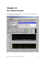
The LabView Example ................................................................................. 72
Using Virtual RGA Systems ......................................................................... 75
What is a Virtual RGA System? ......................................................................... 75
How are Virtual RGA’s Installed? ...................................................................... 75
How do Virtual RGA’s Work? ............................................................................ 76
Are there any limitations to Virtual RGA’s? ........................................................ 76
Using a Virtual System..................................................................................... 77
Vacuum Profile ‘Replay’ File Format........................................................... 96
Background Information .......................................................................... 100
MKS RGA SDK User Manual – SP104015.100 September 2005
4
Chapter 1
Introduction
This manual describes the RGA Communications Library Software Development
Kit (SDK) provided by MKS Instruments that enables the integration of MKS RGA
Control Units into other software applications.
Who should read this manual?
If you are a software developer working in one of the popular programming
languages such as Java, Visual Basic, Visual C++ or LabView, and you wish to
control an MKS RGA control unit and use the data that it acquires directly in your
own software, you should read this manual.
What does the manual include?
The manual includes
•
•
•
•
•
A description of the RGA control unit hardware.
What you need to know about installing and configuring the control unit
hardware
The principles of how to use the software tools provided by the SDK
A full reference guide to the RGA Communications library object model
A description of the example programs and how you can adapt them for your
own use.
What does the manual not include?
The manual does not include any information about MKS’ own software products,
Process Eye® and EasyView®, which also fulfil the function of controlling MKS mass
spectrometers.
What is in the SDK for Windows® computers?
In addition to the Java and ActiveX RGA communications libraries themselves, the
SDK includes the complete RGA Device Management software for installing and
configuring both MKS network control units – e-Vision, e-Vision Plus, Microvision-IP
and HPQ-IP – and serial RS232 control units.
Finally the SDK contains examples of the use of the libraries, which you can use as
the basis for your own development.
What is in the SDK for non-Windows® computers?
If your operating system is not Microsoft Windows®, for example Linux, Unix or Mac,
you should copy the entire contents of the ‘Linux’ folder to your computer and read
the documentation therein. You will find the Java JAR library file and the Java
example files. MKS Instruments does not provide any hardware management
software for non-Windows operating systems.
MKS RGA SDK User Manual – SP104015.100 September 2005
5
However e-Vision and e-Vision Plus control units require no external management
because browsing to the control unit with your favourite browser software performs
all user-configurable control unit options. All network instruments have browser
interfaces and support the applet that can control the RGA, acquire data, tune the
instrument and run diagnostic tests.
You cannot use the SDK on non-Windows computers to communicate with serial
RS232 control units such as Microvision Plus and HPQ2. You can only use the SDK
with Microvision-IP, HPQ2-IP, e-Vision and e-Vision Plus control units.
MKS RGA SDK User Manual – SP104015.100 September 2005
6
Chapter 2
Installing The CD-ROM Software
Installing on a Windows® Computer
Insert the CD-ROM in a suitable drive. It should auto-run, but if it does not, doubleclick ‘setup.exe’ in the root folder.
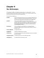
Read the options on the CD-browser window. If you do not already have Acrobat
Reader software installed on your computer, please select the option to install this
first, since all SDK documentation is in PDF format.
The default option is to install the SDK. Selecting this option will launch the install
package, which offers a complete choice of the features to be installed. Several
components can be installed to a folder location of your choice. If you are new to
writing software for RGA’s, be sure to include installation of the examples in your
chosen language(s).
If, after installing the software, you want to install additional components that were
not installed initially, you can do so by launching Add/Remove Programs from Control
Panel.
MKS RGA SDK User Manual – SP104015.100 September 2005
7
Installing on a non-Windows® Computer
The software contained in the ‘Linux’ folder of the CD-ROM should be selfexplanatory and simply requires copying to an appropriate location on an individual
developer’s computer.
MKS RGA SDK User Manual – SP104015.100 September 2005
8
Chapter 3
Hardware Management
The tools provided with this SDK can be used with any of the following control units
Micovision Plus and HPQ2 with serial RS232 connections.
You can work with these control units only if they are connected to Windows
computers. These control units should have a minimum of version 5.0
embedded core and application software. You must access them on a
computer that is running at least version 5.10 of the ‘RGAServer.exe’
application software. This application is the data server to which you connect.
(RGAServer.exe can be installed as part of the SDK.)
Micovision-IP and HPQ-IP with network connections.
All computer operating systems can control both these control units provided
they have version 5.0 embedded core and application software and version
5.00 of the internal data server software as a minimum.
e-Vision® and e-Vision Plus® control units with network connections.
You can work with all versions of these control units. Once again, the data
server to which your software connects is embedded in the control unit.
The Network Control Units
All the control units listed above that have network connections provide a web
interface accessible from any browser software. This web interface permits control of
the RGA and provides a graphical view on the data being acquired in real time.
Typically you would use this as a method for quickly determining the correct
behaviour of the RGA and also for ‘tuning’ its mass alignment and the resolution of
the individual peaks. The web interface provided by these control units is an
example of a Java applet written by the same MKS software developer that has
developed the software for this SDK.
The IP addressing options can also be set by browsing to the control unit. All the
network instruments support DHCP, but it is likely that you will be assigning static IP
addresses because the instruments will be on a small local network without a DHCP
server. All network instruments are shipped with the default address of
192.168.0.250. The client computer must be on the same subnet as the control unit
for it to serve up the pages correctly.
If it becomes necessary to update the embedded software in a network control unit, it
is normally set into FTP mode and an FTP client application is used to transfer the
new files. MKS often provides ‘download packages’ that contain several files and
which perform the operation by means of a ‘Wizard’ – but these ‘Package
Downloads’ are only available for Microsoft Windows® computers.
MKS RGA SDK User Manual – SP104015.100 September 2005
9
The Serial RS232 Control Units
You will be controlling these control units by connecting to the network address of the
computer to which the control unit(s) are connected. This computer must be running
Microsoft Windows® and at least version 5.10 of the RGA Server software. One
instance of this server application can support multiple control units.
Obviously, none of the serial control units have a web interface. All aspects of
hardware configuration and set-up are undertaken using the supplied Windows
applications. Unless you wish to include mass alignment and tuning algorithms in
your own software, you will probably need to have at least one instance of the full
EasyView or Process Eye suite on a computer that can be used for diagnostic and
RGA maintenance purposes. This software is available separately from the MKS
Spectra RGA Group.
Software Protocol Version
All the different control units share the same software protocol versioning strategy.
When you make a connection to any data server, you get two important pieces of
information.
The installed version
The minimum compatible version.
You can only connect to a server if the protocol version of the libraries that are
installed on the computer (the required version) is greater than or equal to the
minimum compatible version reported by the sensor. This checks that the computer
software is not too old for the control unit. It is up to the computer software itself to
check that the control unit is not too old to work with the current version of the client
application.
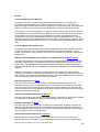
Hardware Programmable Features of RGA Control Units
You will almost certainly find it necessary to program the ion source settings of the
analyser connected to the control unit that you are working with. The ion source has
eight adjustable properties that affect the behaviour and signal response of the
analyser – and hence its calibration. These properties are
Low mass alignment
High mass alignment
Low mass resolution
High mass resolution
Ion energy
Electron energy
Extract potential
Filament emission current
0-65535
0-65535
0-65535
0-65535
0 to
0 to 130 volts
0 to 130 volts
0 to 5 mA
The ion source settings determine the ion amps that arrive at the detector and,
therefore, directly determine the magnitude of the peaks measured. All analysers
have a Faraday detector – a simple detector that generates a current by collecting
the ions that fall onto it. Some analysers have an additional ‘multiplier’ detector. A
multiplier detector generates an output current that is a multiple of the incident
current. The multiple is referred to as the Detector Gain. This gain is not a fixed
number but is itself adjustable by increasing or decreasing the voltage applied to the
detector. The voltage-gain response is non-linear. Typically the gain is about 50 at –
700V and 1000 at –900V. Unfortunately multiplier detectors have a finite life in a
direct relationship to the amount they are used. As time goes by increasingly
negative voltages must be applied to achieve the same gain that they had when new.
MKS RGA SDK User Manual – SP104015.100 September 2005
10
In addition to any gain introduced by the detector (the Faraday detector, by definition,
always has a gain of 1), all MKS control units feature at least two electronic gain
ranges, the smallest of which also has, by definition, a value of 1.
The calibration of an analyser is essentially the transfer function that converts ion
amps injected into the electronics by the detector to the partial or total pressure value
that created the signal when the electronic gain is 1.
It should be apparent that with all these adjustable parameters, it is necessary to
create some ordered arrangement whereby one of a number of commonly used
settings can be called up at a particular time. E-Vision control units store one set of
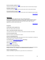
ion source settings. All other control units store a table of six. Each of these source
settings has one (Faraday only detector) or four (dual Faraday and multiplier
detector) detector settings. Each detector setting has two calibration factors – one
for each of the two filaments.
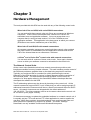
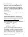
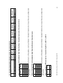
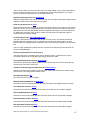
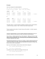
The default settings for all the control units are shown in Table 1 overleaf.
Please note the following important points that affect you as a developer. All the ion
source settings are positive numbers even though some of them in hardware terms
are negative voltages. However, the multiplier detector voltage is negative both in
reality and in software.
The only fixed item in the ion source settings table, which in software is an array (0 to
5) of six items, is the Name. All other values are completely flexible within the
allowable range of the property concerned. So you can change the electron energy
of the “Standard electron energy” row to be any number you like, but it obviously
makes sense that if you want to work at a low electron energy, you should be
adjusting the second row in the array in order to keep the meaning correct.
The ion energy value can affect the sensitivity and peak shape. If you are
particularly interested in low masses you may benefit from using a slightly higher
value. Conversely high masses may benefit from a lower value. The sensitivity of
the analyser will increase with increased emission current – but only up to a point.
Beyond a certain emission current the signal will probably fall. Lower electron
energies may start to result in lower signals generally, but the main advantage is that
they will usually result in much lower ‘doubly ionised’ fragments. The commonest
occasion that this is apparent is when Argon is present. At 70eV electron energy a
significant portion of the argon will appear doubly ionised at an m/e value of 20,
whereas at 40eV all the argon will appear at an m/e value of 40. The extractor
potential on an open source analyser should always be numerically greater than the
electron energy. Beyond that, its impact is secondary compared with the other three
properties.
The table of six source settings (only one in an e-Vision) is stored in non-volatile
RAM within the control unit. Therefore it persists as control units are moved around
or de-powered. The 48 calibration factors are stored at the data server, which is
effectively the control unit itself on e-Vision and –IP control units. However RS232
serial instruments have their data server on the computer to which they are
connected. This means that when you move an RS232 control unit from one
computer to another, or perform a new computer installation, the calibration is ‘lost’.
However, the Windows applications that are associated with the Windows server
provide ways of backing up the settings from one PC and restoring the same settings
file to another PC.
MKS RGA SDK User Manual – SP104015.100 September 2005
11
70
40
85
35
40
70
MKS RGA SDK User Manual – SP104015.100 September 2005
Base pressure RGA
Mid pressure RGA
Leak hunt (helium0
HP Analytical (HPQ2S)
HP General (HPQ2S)
EasyView
7
7
10
5
8
7
110
61
130
58
61
110
20
20
20
20
20
20
0
1
2
3
4
5
7
5
7
7
7
7
Extract
Potential
40
70
40
40
40
40
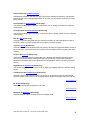
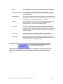
Ion Source Settings Table for HPQ Analysers
ID
Name
Electron Ion
Energy
Energy
Standard Electron Energy
High electron energy
User defined 1
User defined 2
User defined 3
EasyView
0.39
0.7
1.0
0.1
0.16
0.39
Emission
Current
1.0
1.0
1.0
1.0
1.0
1.0
32767
32767
32767
32767
32767
32767
Low mass
alignment
32767
32767
32767
32767
32767
32767
32767
32767
32767
32767
32767
32767
High mass
alignment
32767
32767
32767
32767
32767
32767
32767
32767
32767
32767
32767
32767
0
1
2
3
4
5
1.0
1.0
1.0
1.0
1.0
1.0
High mass
alignment
112
112
112
112
112
112
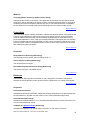
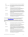
Ion Source Settings Table for Standard and High Resolution Enclosed Source Analysers
ID
Name
Electron Ion
Extract
Emission Low mass
Energy
Energy Potential Current
alignment
5.5
5.5
5.5
5.5
5.5
5.5
32767
32767
32767
32767
32767
32767
70
40
70
70
70
70
0
1
2
3
4
5
Standard Electron Energy
Low electron energy
User defined 1
User defined 2
User defined 3
EasyView
High mass
alignment
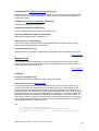
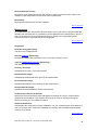
Ion Source Settings Table for Standard and High Resolution Open Source Analysers
ID
Name
Electron Ion
Extract
Emission Low mass
Energy
Energy Potential Current
alignment
32767
32767
32767
32767
32767
32767
32767
32767
32767
32767
32767
32767
32767
32767
32767
32767
32767
32767
32767
32767
32767
32767
32767
32767
Low mass High mass
resolution resolution
32767
32767
32767
32767
32767
32767
Low mass High mass
resolution resolution
32767
32767
32767
32767
32767
32767
Low mass High mass
resolution resolution
12
125
1.0
32767
High mass
alignment
32767
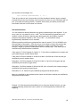
Faraday 4.5e-7
MKS RGA SDK User Manual – SP104015.100 September 2005
0
Detector Settings for HPQ analysers on Source Settings ID=0 and ID=1 and ID=5
ID Name
Factor
0 Faraday
1.5e-8
1 Multiplier1 4.5e-7
2 Multiplier2 4.5e-6
3 Multiplier3 4.5e-5
Each Source setting table entry has two of these tables, one for each filament. By default the factors for all rows of the source settings table
are the same.
Detector Settings Table for Standard and High Resolution Enclosed Source Analysers
ID Name
Factor
0 Faraday
1.5e-6
1 Multiplier1 4.5e-5
2 Multiplier2 4.5e-4
3 Multiplier3 4.5e-3
Each Source setting table entry has two of these tables, one for each filament. By default the factors for all rows of the source settings table
are the same.
32767
Low mass High mass
resolution resolution
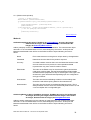
Detector Settings Table for Standard and High Resolution Open Source Analysers and e-Vision Control Units
ID Name
Factor
7.5
32767
40 / 70
0
Standard Electron Energy
Low mass
alignment
Ion Source Settings Table for Analysers with e-Vision Control Units
ID
Name
Electron Ion
Extract
Emission
Energy
Energy Potential Current
13
Faraday 2.25e-7
Faraday 7.5e-8
MKS RGA SDK User Manual – SP104015.100 September 2005
0
Detector Settings for HPQ analysers on Source Settings ID=3
ID Name
Factor
0
Detector Settings for HPQ analysers on Source Settings ID=2 and ID=4
ID Name
Factor
14
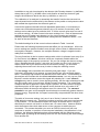
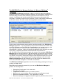
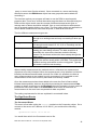
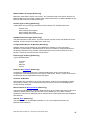
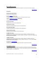
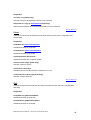
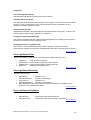
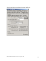
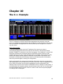
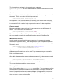
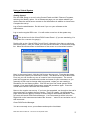
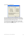
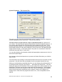
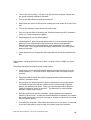
The MKS RGA Device Manager Software for Microsoft Windows®
Computers
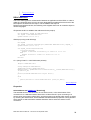
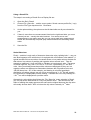
The ‘RGA Device Manager’ application, which is included as part of the SDK on
Windows computers, provides complete installation and configuration capabilities for
the entire range of control units, whether connected to this computer or on the
network. Specifically this includes serial RS232 instruments connected to this
computer or a different computer on the network, as well as all network instruments
on the local subnet. The main screen of the application is shown below.
All the control units referred to above can be ‘auto-discovered’ by the ‘RGA Device
Manager’ application. If you are installing control units for the first time, switch them
on and, if necessary, start the RGA Server application on any remote computer that
has serial instruments. The local instance of the RGA Server will start up
automatically as required. When you launch the application it will ‘discover’ all these
control units. Network instruments are delivered with an IP address of
192.168.0.250. Even if this does not match the subnet of the computer, RGA Device
Manager will still find the control un it, but the first thing you will have to do is to use
the application to re-program the IP address so that it matches your subnet. You will
only be able to connect to instruments using the SDK software libraries if the control
unit is on your subnet. For example, if your computer address is 192.168.1.100,
RGA Device Manager will find it and alert you to the fact that the address of the
control unit should be changed to a 192.168.1.xxx address.
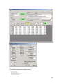
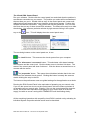
The RGA Device Manager application has full on-line help by pressing the F1 key or
clicking the ‘Help’ button.
Depending on the particular control unit, you can use RGA Device Manager to
perform the following tasks.
o
o
o
o
o
o
Change the ‘friendly name’ of a control unit
Change an IP address
Troubleshoot an RGA to which you cannot connect
Modify the ion source settings, detector settings and calibration directly
Download embedded software – core, application or server
Download ‘packages’ of upgrade software supplied by MKS from time to time
MKS RGA SDK User Manual – SP104015.100 September 2005
15
o
o
o
Configure a control unit’s digital or analog inputs
Change the trip settings (external trip, emission trip, RF trip etc)
Configure any additional inlets
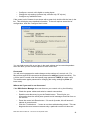
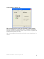
If the control unit of interest is not shown with a green tick, double click the item in the
list. This will display more detailed information. If the unit requires some kind of
configuration, click the ‘Configure Now’ button.
You can right mouse click on an item in the main window and a context-dependent
menu will offer you the relevant options for that control unit.
Passwords
You will need a password to make changes to the settings of a control unit. For
Microvisions and HPQ instruments the password is mksrga1 (case-insensitive). For
e-Vision and IP control units the browser page password is MKS (all upper case).
The web browser applet password for changing the tuning settings is peaks (all
lower case).
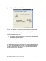
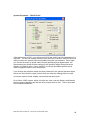
What to do if your unit is not discovered
If the RGA Device Manager does not discover your control unit try the following.
o
Check the power cables and serial or network connections.
o
Read the auto-discovery log on the Details button. This will give you
information about the serial ports opened and all messages received from online servers.
o
Press the control unit Reset button. If it was in ftp mode, this will ensure it
reboots in normal mode.
o
Click the ‘Troubleshoot …’ button to run the troubleshooting wizard. This can
diagnose the most common reasons why a particular control unit does not
MKS RGA SDK User Manual – SP104015.100 September 2005
16
o
appear in the list. These include the action of the Windows XP firewall in
blocking communications between networked items.
o
Make sure that you can ‘ping’ the IP address, using the ping command in a
DOS window.
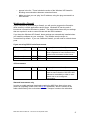
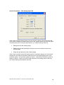
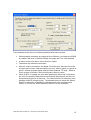
Working with a Firewall
If your computer is protected by a firewall, you will need to program the firewall to
allow access to certain applications and/or ports. Windows XP service pack 2
introduced a firewall to Windows by default. The table below shows the port settings
that are required in order to communicate with the RGA hardware.
If you have the Windows XP firewall, these settings are automatically installed when
you install the software on your computer. The installer sets the scope to
‘unrestricted’ by default. If you use a different firewall, you will need to unblock these
ports.
If you are using RS232 serial instruments
Name
Port
Protocol Scope (where restricted)
RGA Server UDP
10013 UDP
RGA Server 1
RGA Server 2
10014 TCP
10015 TCP
At least your local subnet, if you want
other computers to have access to the
control units connected to the server.
Ditto
Ditto
All instruments
Name
Port
Protocol Scope (where restricted)
RGA Network Listener
10014 UDP
In addition to your local subnet you
need to ensure that the 192.168.0.250
address is accessible in order to autodetect new or un-configured
instruments.
Network instruments only
In order to enable package downloads supplied by MKS from time to time as a
means of upgrading control units, the ftp.exe application, which is located in the
folder referenced by the environment variable ‘comspec’ needs to be unblocked.
MKS RGA SDK User Manual – SP104015.100 September 2005
17
Chapter 4
A ‘Quick Start’ Introduction to The RGA
Communications Library
The RGA Comms library features an extensive set of methods and properties that
deal with all aspects of making a connection to a control unit, taking control, adding
measurements, constructing a scan and acquiring data.
The object model is essentially the same whether you use the ActiveX DLL to
program in, for example, Visual Basic or the Java libraries to target a non-Windows
computer. In all these cases the software installation includes an Object Browser
that you can use to explore all the features of the object model.
For this reason this chapter will give you a general introduction to RGA programming
fundamentals, whatever your programming language.
Please note the following important point. Different programming languages have
their own conventions for differentiating properties and methods. Java and LabView
are rather strict – properties must return one of the basic data types. Anything that
returns another object, for example, is a method. VB is more lax in that properties
can return objects. This example shows the difference.
VB:
MyConnection.SerialNumber(0)
This item is an indexed property
Java:
MyConnection.getSerialNumber(0)
This is a method
LabView:
MyConnection.SerialNumber(0)
This is a method
This manual adopts the VB approach since it is one of the commonest languages,
but you need to remember that, when programming in your chosen language, some
functions listed as properties may in fact be methods.
Having made that point clear, let us now take a ‘Quick Start’ tour of the main
elements of the object model.
The two main high level objects are the RGASensor (which is accessed from the
RGAConnection object) and the Scan (which is accessed from the RGASensor
object).
The RGAConnection object is the server to which you connect. If it is a server
embedded in a network instrument there is obviously only one RGASensor object
associated with it and by default it is selected for use. However, a server running on
a Windows computer could have multiple sensors connected to RS232 ports and
therefore multiple RGASensor objects. Thus the sensor that a program wishes to
MKS RGA SDK User Manual – SP104015.100 September 2005
18
query or control must first be selected. Once connected to a server and having
selected a sensor the RGASensor object has many properties and methods for
controlling it.
The chances are that your program will want to use the RGA to acquire partial
pressure data. There are a several alternative ways that data can be acquired by the
RGA and the object model uses the concept of different measurement types to
manage each of these acquisition methods. One or more individual measurements
can be grouped together and run as a Scan. The Scan object allows an application to
control which measurements have data acquired, in what order and when.
The four different measurement types are:
Barchart
Analog
Peakjump
Singlepeak
Consecutive masses are measured from a starting mass
through to an ending mass and only one reading is taken per
mass.
Consecutive masses are measured starting from startmass0.5 through to end mass+0.5. 32, 16, 8 or 4 readings can be
returned per mass
Individual masses are grouped together and measured with 1
reading per mass being returned. The data acquisition is
essentially the same as the barchart mode but arbitrary
masses can be chosen without the linear sweep through the
mass range.
A single reading can be taken from any position in the mass
range of the sensor usually within 1/32 AMU. This mode uses
a default zeroing mode which must be re-triggered. Typically
this mode is used for leak checking.
When creating measurements the methods return a reference to a measurement
object that is not fully initialised. When the measurement is fully initialised (or failed to
initialise) the MeasurementCreated event will fire. While it is possible to create as
many measurements as are needed in quick succession it is not possible to add
measurements to the Scan until they have been successfully created.
Once the measurements have been added to the scan the Scan’s Start method
initiates data acquisition; data can be polled by accessing the measurements Data
property to obtain a reference to the Readings object but normally it is more useful to
process the entire scans data in the EndOfScan event which is fired when all
measurements in the scan have competed their data acquisition.
The coding requirements for this are explained in more detail below.
The Significant Events
The Connected Event
This event is fired after calling the Connect method on the Connection object. So to
connect to the server at IP address 10.10.100.25, you would call the following
method.
MyConnection.Connect “10.10.100.25”
You would then wait for the Connected event to fire
MKS RGA SDK User Manual – SP104015.100 September 2005
19
MyConnection_Connected (bSuccess As Boolean)
The bSuccess parameter indicates whether the connect attempt succeeded. If
bSuccess is false, there was a problem connecting to the server at the address
specified.
The Controlling Event
This event is fired after invoking the Control method on your selected sensor.
MyConnection.SelectedSensor.Control “Vbrga”, “version 1.0”
Code execution would then continue with the Controlling event
MyConnection_Controlling (bSuccess As Boolean)
The bSuccess parameter indicates whether the control attempt succeeded. If
bSuccess is False there could be several reasons the most likely of course being
that the control unit is in use by another user. This would have been apparent before
attempting the Control method by examining the State property of the
SelectedSensor
If MyConnection.SelectedSensor.State = Available Then ….
The MeasurementCreated Event
This event is fired after invoking one of the methods that add a measurement to the
control unit. These methods are
AddBarchart
AddPeakJump
AddAnalog
AddSinglePeak
Code execution would then continue with the MeasurementCreated event. Note that
it is not uncommon to add several measurements to the control unit even though you
may not wish to use them all immediately. A typical code fragment might look like
this
With MyConnection.SelectedSensor
.AddBarchart “Barchart”, 1, 20, PeakCenter, 5, 1, 0, 0
With .AddPeakJump “PeakJump”, PeakCenter, 5, 1, 0, 0
.Masses.Add 28
.Masses.Add 32
.Masses.Add 40
End With
End With
WaitForMeasurementCount = 2
The code execution would continue with the MeasurementCreated event
MyConnection_MeasurementCreated (bSuccess As Boolean, theMeasurement As
Measurement)
Typically this code would check for the bSuccess parameter and decrement the
global WaitForMeasurementCount variable. Complete success would require
MKS RGA SDK User Manual – SP104015.100 September 2005
20
bSuccess to be true at each firing of the event and when
WaitForMeasurementCount reached zero the code would continue with the next
task.
The StartScan and EndOfScan Events
These events are fired once the control unit is scanning and acquiring data. You
start the scanning process by invoking the Start method on the Scan object. You
stop scanning by calling the Stop method.
Scan.Start 2
At the end of each scan the EndOfScan event is fired and you can use this event to
access the data for the current scan
MyConnection_EndOfScan (theScan As Scan)
The theScan reference to the Scan object provides access to many properties, but
in particular the data acquired during the scan, as follows
Mass28Value = theScan.Measurements(“Barchart”).Data.Readings(“Mass 28”)
The FilamentChange Event
This event is the prime means of knowing when the filament state changes. It is not
necessary to poll for the filament status. After initially discovering the filament status
by reading the property value on the Filament object the FilamentChange event will
inform you of any changes in state as they happen.
A code fragment for the FilamentChange event might look like
Sub MyConnection_FilamentChange (theFilaments As RGAFilaments)
IsOn = theFilaments.filamentOn
Xtripped = (theFilaments.SummaryState And Xtripped) <> 0
The LinkDown Event
This event is the prime means of handling a broken connection. Some control units
(even some network ones) have both a TCP/IP connection and a real or virtual serial
connection to the source of the data. Either of these connections can fail and the
result is effectively the same – there will be no more data! You do not need to take
any action to stop scanning. It is important, however, that if you have kept any
references to the MyConnection.SelectedSensor object that these be released since
it is no longer available.
A code fragment for the LinkDown event might look like
Sub MyConnection_LinkDown (Reason as LinkDownReason)
Set MySensorReference = Nothing
MKS RGA SDK User Manual – SP104015.100 September 2005
21
Significant Properties and Methods
You will find that you make extensive use of these properties and methods when you
code your event handlers.
For the Connection Object
The Connect method is used to initiate a new connection, and the Select method is
required if there is more than one sensor at that address. The SelectedSensor
property gives you a reference to the specific sensor as an RGASensor object.
For the RGASensor Object
You will need to check properties such as MaximumMass and EgainCount to ensure
that you work within the range of the instrument. You can obtain a considerable
amount of information about the sensor even when another user is controlling it.
However you will need to invoke the Control method in order to change settings or
acquire data. You will use the SourceSettings property to set the working condition
of the ion source. You will access the scan data by obtaining a reference to the Scan
object and control the filaments by obtaining a reference to the Filaments object.
You will certainly want to download measurement definition(s) to the sensor from
which you can construct the measurements that make up the scan.
For the Scan Object
The scan object has methods to add sensor measurements into the scan. It has
methods to start and stop scanning. The scan object has properties that lead directly
to the partial pressure data readings.
This completes the Quick Tour of the object model. You can browse both the Java
and ActiveX implementations in their entirety by clicking the relevant shortcut on the
Start | Programs menu. The following chapter provides a complete reference to a all
the features.
MKS RGA SDK User Manual – SP104015.100 September 2005
22
Chapter 5
RGAComms ActiveX Object Model
Reference
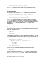
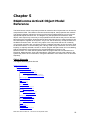
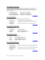
The RGAComms ActiveX component provides an extensive list of objects that can be used to
manipulate the RGA. This reference documents all the objects, their properties and methods.
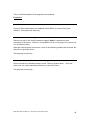
The following diagram outlines the structure of the object model and allows you to link to the
appropriate objects reference text. The diagram only lists properties that reference other
objects, each object may have many more properties and methods but they tend to deal with
base types such as integers, floats and strings and have been left out to make it easier to see
how the objects fit together in the system. As you can see the hierarchy of objects starts from
the RGAConnection class. This is the only object in the component that can be created by
your program, all others are ‘sub-objects’ that are created dynamically as the connection finds
out about the RGA it is communicating with. Having made a tcp/ip connection to a server and
implicitly or explicitly selected a sensor to use the program will spend most of it’s time dealing
with the RGASensor object referenced by the SelectedSensor property of the
RGAConnection. For most data acquisition tasks the program will then concentrate on the
Filaments, Measurements, Scan and Data objects, while there are many other objects in the
system they tend to be for information, tuning and calibration of the sensor which is done less
frequently.
Object Hierarchy
The Object Hierarchy looks like this
RGAConnection
├ProtocolInfo
└SelectedSensor
├SourceSettings()
│ └SourceSettings
│
└DetectorSettings()
│
└DetectorSettings
├Multiplier
├RF
├Inlets()
│ └Inlet
├Filaments
├Measurements()
│ └Measurement
├Scan
│ └Measurements()
│
└Measurement
├AnalogInputs()
│ └AnalogInput
├AnalogOutputs()
│ └AnalogOutput
├RVC
├Cirrus
├Rollover
├DigitalPorts()
MKS RGA SDK User Manual – SP104015.100 September 2005
23
│ └DigitalPort
└TotalPressure
RGAConnection
This is the starting point for all interaction between an application and the RGA. In order to
make the component easy to use in as many languages as possible all events for all of the
RGA objects are fired from this object. The CLASSID of the object is
RGAComms.RGAConnection, the following code snippets show how to create the object in
various languages.
VB (ensure the DLL is added to the references for the project)
Dim WithEvents myRGA As RGAConnection
Set myRGA = New RGAConnection
myRGA.Connect(“127.0.0.1”)
VBScript (running under WScript)
Dim myRGA
Set myRGA = WScript.CreateObject(“RGAComms.RGAConnection”,”myRGA_”)
myRGA.Connect(“127.0.0.1”)
Sub myRGA_Connected(bConnected)
If bConnected Then
MsgBox “Connected successfully to sensor at 127.0.0.1”
Else
MsgBox “Failed to connect to sensor 127.0.0.1”
End If
End Sub
C++ (using Visual C++ with COM smart pointers)
#import "RGAComms.dll"
using namespace RGACommsLib;
IRGAConnectionPtr pRGAConnection;
HRESULT hRes = pRGAConnection.CreateInstance(__uuidof(RGAConnection));
if(hRes==S_OK)
{
printf(“Created RGAConnection object OK\n”);
}
else
{
printf(“Failed to create RGAConnection [0x%x]\n”,hRes);
}
Back to Object tree
Properties
SelectedSensor As RGASensor [Read-Only]
The selected sensor if the connection is to a sensor server, or the actual sensor if the
connection is to a dedicated sensor like eVision or MicroVisionIP. Upon connecting to a
sensor server this property will be NULL and the program must decide which sensor to select
by checking the SensorCount, SensorSerialNo and SensorName properties. Having decided
which sensor to select the Select method should be used to select the sensor for this
connection.
MKS RGA SDK User Manual – SP104015.100 September 2005
24
Protocol As ProtocolInfo [Read-Only]
The sensor protocol information. If an attempt to connect to a sensor fails then it might be due
to the sensor not supporting the appropriate protocol version. This object allows an
application to see the version required by this version of the RGAComms library and if the
sensor did accept a TCP/IP connection then you can also find out the sensors protocol
version details.
SensorCount As Long [Read-Only]
The number of sensors available on this server, for eVision and MicroVision IP sensors this
will be 1 but for a windows server supporting MicroVision+ units it can be any number.
SensorSerialNo As String [Read-Only]
This property allows access to the serial number of a sensor connected to the server, it is
accessed like an array where valid indexes are between 0 and SensorCount-1. For
MicroVision+ sensors where the exact sensor must be selected this property can be used to
verify that the server currently knows about the serial number you would like to select.
Dim n As Long
For n=0 To myRGA.SensorCount-1
Debug.Print “Serial# “ & myRGA.SensorSerialNo(n)
Next
SensorName As String [Read-Only]
This is similar to the SensorSerialNo property except that it returns the friendly name
assigned to the sensor.
Back to Object tree
Methods
Connect(Address As String)
Connects over TCP/IP to the sensor or sensor server at the address specified. This method
returns immediately and the Connected event will fire some time later indicating success or
failure of the connection operation.
Refresh
This method forces the server to re-read its connections and to re-acquire the settings from
the control unit. Normally the server automatically detects if instruments come back on-line,
for example. Sometimes it may be beneficial to force the server to perform a Refresh, which
is effectively the same as having it start over again.
Select(Index As Variant)
When a connection has been made to a windows server that is in control of MicroVision+
sensors connected via the RS232 interface it is necessary to select the appropriate sensor.
Index can be the numeric index in the SensorSerialNo or SensorName properties or it can be
the name or serial number text. While this method will work with all sensor types it is
redundant for network enabled sensors such as the eVision or MicroVision IP. See
Connected event description for more details of use.
Back to Object tree
MKS RGA SDK User Manual – SP104015.100 September 2005
25
Events
Connected(bSuccess As Boolean)
Following a call to the Connect method this event will eventually fire. The bSuccess
parameter indicates whether a successful connection was made or not. In the event of
bSuccess being False then the ProtocolInfo property can be checked to see if the connection
failed as a result of a protocol version issue or because of a lack of network connectivity.
If bSuccess is True and the application is using an eVision or MicroVision IP sensor then the
SelectedSensor property will be valid and allow access to the information about the sensor. If
the application is communicating with a windows server that is managing MicroVision+
sensors then it will need to use the Select method to select the appropriate sensor. Having
selected a sensor the Connected event will fire once again, indicating either a failure to select
and download information about the sensor or success in which case SelectedSensor will be
valid.
Controlling(bInControl As Boolean)
Following a call to the selected sensors Control method this event will fire indicating whether
control was granted or not. If control was not granted then the sensor is either in use by
another connection or is not in a state where it can be controlled, for example it might require
configuration.
MeasurementCreated(bSuccess As Boolean, theMeasurement As Measurement)
This event fires following a call to one of the RGASensor.Measurements methods to create
and add a measurement. If a measurement fails to be created at the sensor then bSuccess
will be False. The theMeasurement parameter always references the measurement object
that was returned from the call to AddBarchart, AddAnalog, AddPeakJump or AddSinglePeak
methods.
Note that it is possible to create many measurements in one go by calling the AddXXX
methods successively but until the measurements are fully created they cannot be added to a
scan. Similarly for PeakJump measurements, masses cannot be added/removed or changed
until the underlying measurement has been fully created.
StartingScan(theScan As Scan)
This event fires when a scan is just starting. The theScan parameter references the
RGASensor.Scan property and provides access to the current scan number and how many
scans are still to be done before a call to Scan.Resume will be needed. The purpose of this
event is to allow any UI to be updated to show scan progress and to keep the scan running by
calling Scan.Resume as required.
FilamentChange(theFilaments As Filaments)
This event is fired whenever the filaments state changes. This allows an application to update
any filament UI or abort what it is doing if the filaments trip off for some reason.
EndOfScan(theScan As Scan)
This event is fired when the last piece of data for a scan has been acquired. Access to the
data is through the Data property of the individual measurements in the scan. Note that no
more data will be processed until this event returns, instead it will be buffered and processed
upon completion of this events processing.
FilamentOnTime(theFilaments As Filaments)
If the filament is configured to have a maximum on time and it is on this event will fire
approximately every 2 seconds. The Filaments object allows access to the remaining time
MKS RGA SDK User Manual – SP104015.100 September 2005
26
which can be reset. The purpose of this event it to allow update of any UI that might allow a
user to reset the filament on time or to automatically reset it if the application is in a state
where it must ensure filaments don’t accidentally switch off.
DigitalInputChange(thePort As DigitalPort)
Whenever digital input lines change, this event will fire. The thePort parameter references the
DigitalPort object whose input lines have changed.
InletChange(ActiveInlet As Inlet)
Whenever the active inlet changes as a result of a valve change from an RVC or VSC device
this event will fire. The ActiveInlet parameter is a reference to the newly selected inlet. Note
that all data will have the appropriate inlet factor applied automatically. This event allows for
UI update and re-scaling of any charts to reflect the new pressure ranges that might be
acquired with the new inlet setting.
LinkDown(Reason As rgaLinkDownReasons)
This event fires whenever the link to the sensor or server is lost. The Reason parameter
identifies where the problem arose. For example if the sensor is a MicroVision+ and the
RS232 cable was unplugged then the Reason value would indicate a problem with the Serial
link.
This is a pretty catastrophic problem and the connection will need to be re-made when the
sensor is available again.
RefreshComplete(bSuccess As Boolean)
This event is fired on completion of the server refresh method. If bSuccess is True the
information about all the connected instrument(s) will be up to date.
AnalogInputReading(theInput As AnalogInput)
Whenever an analog input reading is sent from the sensor this event will fire allowing easy
access to the new value of the input.
TotalPressureReading(theTotalPressure As TotalPressure)
Whenever a total pressure reading is sent from the sensor this event will fire allowing easy
access to the new total pressure reading value.
RFTripState(theRF As RF)
Fires when the RF Trip state changes
MultiplierState(theMultiplier As Multiplier)
If the sensor has a multiplier fitted then this event fires when the Multiplier status changes
CirrusState(theCirrus As Cirrus)
If the sensor has Cirrus hardware then this event fires when the Cirrus status changes
RVCPumpState(theRVC As RVC)
If the sensor has an RVC fitted then this event fires when the RVC pump state changes
RVCHeaterState (theRVC As RVC)
If the sensor has an RVC fitted then this event fires when the RVC heater state changes
RVCValveState (theRVC As RVC)
If the sensor has an RVC fitted then this event fires when the RVC valve state changes
MKS RGA SDK User Manual – SP104015.100 September 2005
27
RVCInterlocksState (theRVC As RVC)
If the sensor has an RVC fitted then this event fires when the RVC interlocks state changes
RVCStatus (theRVC As RVC)
If the sensor has an RVC fitted then this event fires when the RVC status state changes
RVCDigitalInputState (theRVC As RVC)
If the sensor has an RVC fitted then this event fires when the RVC digital input state changes
Back to Object tree
RGASensor
This object represents a particular sensor and is accessed through the
RGAConnection.SelectedSensor property. Initially the RGAConnection selects the sensor
and downloads information about the sensors configuration. All this information can be
accessed but no data can be acquired until control of the sensor is taken. Only one
application can control a sensor at any time.
Back to Object tree
Properties
SerialNumber As String [Read-Only]
Returns the serial number of the sensor.
State As rgaInfoAvailableStates [Read-Only]
The state of the sensor when the connection was made and information downloaded.
Name As String [Read-Only]
Returns the friendly name assigned to the sensor
Version As String [Read-Only]
Returns the sensor software version, this can be used to ensure an application is working with
the appropriate version of software if necessary.
SourceSettings As SourceSettingsCollection [Read-Only]
Gets at the RGA’s source settings collection.
Inlets As Inlets [Read-Only]
Gets at the RGA’s inlets collection.
EGainCount As Integer [Read-Only]
Number of electronic gains that the sensor can apply when acquiring data. See the Hardware
Management section for more details on how the RGA electronics acquire data.
EGain As Single [Read-Only]
Gets the actual electronic gain value for a given index from 0 to EGainCount-1.
MKS RGA SDK User Manual – SP104015.100 September 2005
28
MaximumMass As Integer [Read-Only]
Maximum mass that the sensor can monitor. The complete range of the sensor will be 0.5 to
MaximumMass+0.5 for Analog or Single Peak measurements and 1 to MaximumMass for the
Barchart and PeakJump measurement types.
DetectorType As String [Read-Only]
A descriptive string for the type of detector that the sensor has. Possible values are:
Faraday only
Dual Faraday and multiplier
Dual Faraday and SCEM
Dual Faraday and advanced SCEM
PeakResolution As Integer [Read-Only]
The peak resolution of the sensor. This is the number of points across one AMU that can be
sampled. Current sensors from MKS use a value of 32.
ConfigurableIonSource As Boolean [Read-Only]
Whether the ion source settings can be modified from software or if they are fixed in
hardware. For MicroVision+ and MicroVision IP units it is possible to modify parameters for
Ion Energy, Electron Energy, Extract Volts and Emission Current but for the eVision and
eVision+ units they have just one set of fixed values.
FilamentType As String [Read-Only]
Type of filaments fitted:
Tungsten
Thoria
Rhenium
Yttrium
Filaments As Filaments [Read-Only]
Accesses the Filaments object which supports reading back of the current state and
configuration of the filaments when not in control of the sensor. When in control of the sensor
the filaments can be manipulated through this object.
InControl As Boolean
Gets whether this connection is in control of the sensor. Control can be released by setting
this property to False. The Controlling event will fire when the sensor acknowledges that
control has been released.
Measurements As Measurements [Read-Only]
The sensors measurements collection. Measurements can be created and removed from this
collection. Measurements from this collection can be added to a scan. When a scan is
stopped the scan’s list of measurements is cleared but the measurements are still available in
this collection.
Scan As Scan [Read-Only]
The sensors scan, it controls data acquisition of 1 or more measurements from the
Measurements collection.
MKS RGA SDK User Manual – SP104015.100 September 2005
29
PressureUnits As rgaPressureUnits
Gets/Sets the pressure units used to report all pressure readings and factors. The default is
Pascal but this can be changed depending on the units you are used to working in or would
like to display.
AnalogInputs As AnalogInputs [Read-Only]
The sensors analog inputs collection. If the sensor has no analog inputs then the collection
will be empty.
AnalogOutputs As AnalogOutputs [Read-Only]
The sensors analog outputs collection. If the sensor has no analog outputs then the collection
will be empty.
RVC As RVC [Read-Only]
If the sensor has an RVC fitted then this property will return an object that allows access to
the RVC’s state. If no RVC is fitted then this property will return nothing.
Cirrus As Cirrus [Read-Only]
If the sensor has Cirrus hardware then this property will return an object that allows access to
the Cirrus state. If the sensor does not have the Cirrus hardware then this property will return
nothing..
Rollover As Rollover [Read-Only]
If the sensor supports rollover compensation (e.g. HPQ2s and HPQ-IP) then this property
returns an object that allows reading and writing of the rollover compensation algorithm
variables. If the sensor does not support rollover compensation then this property will return
nothing.
DigitalPorts As DigitalPorts [Read-Only]
The sensors DigitalPorts. If the sensor has no digital I/O capability then this collection will be
empty.
TotalPressure As TotalPressure [Read-Only]
Gets the sensors total pressure object if the sensor is configured to have an external total
pressure gauge. If the sensor is not configured with a gauge this property will return nothing.
Back to Object tree
RF As RF [Read-Only]
Gets at the sensors RF configuration and state
Back to Object tree
Multiplier As Multiplier [Read-Only]
Gets the Multiplier object if the sensor has a multiplier fitted
Back to Object tree
MKS RGA SDK User Manual – SP104015.100 September 2005
30
Methods
Control(AppName As String, AppVersion As String)
Attempts to take control of the sensor. The application should pass it’s name and a version
string which will be returned by the sensor to other connections allowing them to see what is
controlling the sensor and what IP address they are at. This method will return immediately
but eventually the Connected event will fire indicating success or failure to take control.
Back to Object tree
ProtocolInfo
The ProtocolInfo object is always available to indicate the required version of the protocol that
a sensor must implement in order for the control to be able to connect. In the Connected
event the fields of SensorVersion and SensorMinCompatibleVersion will be filled in if the
bConnected parameter is True. If the bConnected parameter is False then they may be filled
in which indicates that the control was able to make a tcp/ip connection to the sensor but it’s
protocol version is either incompatible with the control or some other network error occurred
after making the initial connection.
Back to Object tree
Properties
RequiredVersion As String [Read-Only]
The required protocol version, this is currently set at 1.2.
SensorVersion As String [Read-Only]
The sensors protocol version
SensorMinCompatibleVersion As String [Read-Only]
The sensors minimum compatible version
Back to Object tree
Filaments
The Filaments object provides information on the configuration and state of the sensors
filaments as well as allowing control of them when the application is in control of the sensor.
Back to Object tree
Properties
FilamentOn As Boolean
Gets/Sets the filaments on/off state. Setting this property will attempt to put the filaments into
the requested on or off state, this will result in one or more FilamentChange events.
SelectedFilament As Integer
Gets/Sets the selected filament 1 or 2. Switching between filaments 1 and 2 will result in one
or more FilamentChange events.
TripState As rgaFilamentTrips [Read-Only]
Indicates if the filament is in tripped state or not and if so, the reason for the trip.
MKS RGA SDK User Manual – SP104015.100 September 2005
31
SummaryState As rgaFilamentSummary [Read-Only]
Indicates the summary state of the selected filament. Only on and off are guaranteed states
but some sensors such as the MicroVision+ and IP will provide transient warming up and
cooling down states.
XTripMode As rgaFilamentXTripMode [Read-Only]
Indicates the external trip configuration.
XTripEnabled As Boolean [Read-Only]
Indicates whether the external trip input is enabled or not.
EmissionTripEnabled As Boolean [Read-Only]
Indicates if the emission trip is enabled or not.
MaxOnTime As Long [Read-Only]
The maximum time in milliseconds that the filaments will stay on without being re-set. 0
indicates the filaments will stay on indefinitely.
RemainingOnTime As Long
Gets/Sets the time remaining in milliseconds for filaments to stay on if MaxOnTime is not 0.
Back to Object tree
Measurements
This collection allows an application to access the measurements of a sensor as well as
create new ones or delete already existing ones. Measurements should not be created or
deleted while the sensor is scanning.
Back to Object tree
Properties
Count As Long [Read-Only]
Gets the number of measurements currently set up in the sensor
Item(Index As Variant) As Measurement
Gets a specific measurement from the collection. Index can be a numeric index from 0 to
Count-1 or the name of the measurement. Note that accessing measurements from this
collection returns the base Measurement type which all measurements are derived from. If
you need to get at the properties of a specific measurement type then you must query for the
appropriate interface, for late bound languages such as script you can access methods and
properties of the specific measurement type as they are queried for at runtime anyway. If
code needs to check the type of a measurement it can use the Measurement.Type property.
The following example shows how one might access a measurement that is known to be a
PeakJumpMeasurement in both VB and C++.
VB
Dim peakjump as PeakJumpMeasurement
Set peakjump = myRGA.SelectedSensor.Measurements(“peaks”)
peakjump.Masses(0).Mass = 18
‘ Change first peak mass to be 18
MKS RGA SDK User Manual – SP104015.100 September 2005
32
C++ (Without smart pointers)
_variant_t vIndex(“peak”);
IMeasurement* pIMeasurement=NULL;
if(pIMeasurements->get_Item(vIndex,&pIMeasurement)==S_OK)
{
IPeakJumpMeasurement* pIPeakJump=NULL;
pIMeasurements>QueryInterface(__uuidof(IPeakJumpMeasurement),(void**)&pIPeakJump);
// Use the peakjump measurement
…
pIPeakJump->Release();
}
Back to Object tree
Methods
AddPeakJump(Name As String, FilterMode As rgaFilterModes, Accuracy As Integer,
EGainIndex As Integer, SourceIndex As Integer, DetectorIndex As
Integer) As PeakJumpMeasurement
Adds a peakjump measurement to the collection of measurements. The measurement object
returned is in an uninitialised state until it is acknowledged by the sensor. At this point the
MeasurementCreated event will fire on the RGAConnection object indicating success or
failure.
Name
Each measurement must be given a unique name by the application.
FilterMode
Determines how the data for the peaks is acquired.
Accuracy
A number between 0 and 8 where 0 is the fastest but least accurate
and 8 is slower but more precise, the exact speeds and data
improvements vary from model to model of sensor.
EGainIndex
The index in the EGain array for the electronic gain that should be
used when acquiring data. See the DetectorSettings EGainUsable
and MaxPressure properties for help on selecting the correct gain. Not
all electronic gains will be allowed depending upon the configuration
and type of sensor.
SourceIndex
The index into the SourceSettings collection for the settings that
should be used while acquiring data for this measurement.
DetectorIndex
The index into the chosen SourceSettings Detectors array. This is
always between 0 and 3 where 0 is the Faraday detector and 1,2 and
3 use a multiplier with a configurable gain.
AddAnalog(Name As String, StartMass As Integer, EndMass As Integer, PointsPerPeak
As Integer, Accuracy As Integer, EGainIndex As Integer, SourceIndex
As Integer, DetectorIndex As Integer) As AnalogMeasurement
Adds an analog measurement to the collection of measurements. The measurement object
returned is in an uninitialised state until it is acknowledged by the sensor. At this point the
MeasurementCreated event will fire on the RGAConnection object indicating success or
failure.
MKS RGA SDK User Manual – SP104015.100 September 2005
33
Name
Each measurement must be given a unique name by the application.
StartMass, EndMass
The mass span that will be acquired by this measurement. Whole
AMU’s are specified but the actual range spanned will be StartMass0.5 to EndMass+0.5
PointsPerPeak
The number of points to take across each AMU. The maximum for this
is specified by the sensors PeakResolution property. The value must
be a power of 2 so typical values are 2, 4, 8, 16 and 32.
Accuracy
A number between 0 and 8 where 0 is the fastest but least accurate
and 8 is slower but more precise, the exact speeds and data
improvements vary from model to model of sensor.
EGainIndex
The index in the EGain array for the electronic gain that should be
used when acquiring data. See the DetectorSettings EGainUsable
and MaxPressure properties for help on selecting the correct gain. Not
all electronic gains will be allowed depending upon the configuration
and type of sensor.
SourceIndex
The index into the SourceSettings collection for the settings that
should be used while acquiring data for this measurement.
DetectorIndex
The index into the chosen SourceSettings Detectors array. This is
always between 0 and 3 where 0 is the Faraday detector and 1,2 and
3 use a multiplier with a configurable gain.
AddBarchart(Name As String, StartMass As Integer, EndMass As Integer, FilterMode
As rgaFilterModes, Accuracy As Integer, EGainIndex As Integer,
SourceIndex As Integer, DetectorIndex As Integer) As
BarchartMeasurement
Adds a barchart measurement to the collection of measurements. The measurement object
returned is in an uninitialised state until it is acknowledged by the sensor. At this point the
MeasurementCreated event will fire on the RGAConnection object indicating success or
failure.
MKS RGA SDK User Manual – SP104015.100 September 2005
34
Name
Each measurement must be given a unique name by the application.
StartMass, EndMass
The mass span that will be acquired by this measurement. Whole
AMU’s are specified but the actual range spanned will be StartMass0.5 to EndMass+0.5
FilterMode
Determines how the data for the peaks is acquired.
Accuracy
A number between 0 and 8 where 0 is the fastest but least accurate
and 8 is slower but more precise, the exact speeds and data
improvements vary from model to model of sensor.
EGainIndex
The index in the EGain array for the electronic gain that should be
used when acquiring data. See the DetectorSettings EGainUsable
and MaxPressure properties for help on selecting the correct gain. Not
all electronic gains will be allowed depending upon the configuration
and type of sensor.
SourceIndex
The index into the SourceSettings collection for the settings that
should be used while acquiring data for this measurement.
DetectorIndex
The index into the chosen SourceSettings Detectors array. This is
always between 0 and 3 where 0 is the Faraday detector and 1,2 and
3 use a multiplier with a configurable gain.
AddSinglePeak(Name As String, mass As Single, Accuracy As Integer, EGainIndex As
Integer, SourceIndex As Integer, DetectorIndex As Integer) As
SinglePeakMeasurement
Adds a single peak measurement to the collection of measurements. The measurement
object returned is in an uninitialised state until it is acknowledged by the sensor. At this point
the MeasurementCreated event will fire on the RGAConnection object indicating success or
failure.
Name
Each measurement must be given a unique name by the application.
Mass
The mass that will be measured. This can be fractional.
Accuracy
A number between 0 and 8 where 0 is the fastest but least accurate
and 8 is slower but more precise, the exact speeds and data
improvements vary from model to model of sensor.
EGainIndex
The index in the EGain array for the electronic gain that should be
used when acquiring data. See the DetectorSettings EGainUsable
and MaxPressure properties for help on selecting the correct gain. Not
all electronic gains will be allowed depending upon the configuration
and type of sensor.
SourceIndex
The index into the SourceSettings collection for the settings that
should be used while acquiring data for this measurement.
DetectorIndex
The index into the chosen SourceSettings Detectors array. This is
always between 0 and 3 where 0 is the Faraday detector and 1,2 and
3 use a multiplier with a configurable gain.
MKS RGA SDK User Manual – SP104015.100 September 2005
35
Remove(Index As Variant)
Removes a single measurement from the collection. Index can be the numeric index in the
collection of the measurement or the name of the measurement.
RemoveAll()
Removes all measurements from the collection
Back to Object tree
Measurement
All measurements are derived from this base object which holds common properties that are
shared by all measurements. It is possible to access data when the measurement is part of a
scan, the specific type of the measurement to aid in casting to the appropriate specific
measurement type in type safe early bound languages.
Back to Object tree
Properties
Name As String [Read-Only]
The name of the measurement
Data As Readings [Read-Only]
Accesses the data of the measurement if it is currently involved in a scan
Type As rgaMeasurementTypes [Read-Only]
The real type of this measurement
Accuracy As Integer
Gets/Sets the accuracy of the measurement
EGainIndex As Integer
Gets/Sets the selected electronic gain for the measurement
SourceIndex As Integer
Gets/Sets the selected source settings for the measurement
DetectorIndex As Integer
Gets/Sets the selected detector for the measurement
UseRolloverCorrection As Boolean
Determines if the measurement uses total pressure readings as a way to compensate for
quadrupole rollover effects. This property can only be set True for sensors that support
rollover correction, e.g. the HPQ2s or HPQ-IP.
Initialised As Boolean
Gets whether the measurement is fully initialised or not. For a measurement to be added to a
scan it must have been created and initialised successfully. See the MeasurementCreated
event for more details.
Back to Object tree
MKS RGA SDK User Manual – SP104015.100 September 2005
36
BarchartMeasurement
The BarchartMeasurement object allows acquisition of a series of consecutive masses.
Back to Object tree
Properties
Name As String [Read-Only]
The name of the measurement
Data As Readings [Read-Only]
Accesses the data of the measurement if it is currently involved in a scan
Type As rgaMeasurementTypes [Read-Only]
The real type of this measurement
Accuracy As Integer
Gets/Sets the accuracy of the measurement
EGainIndex As Integer
Gets/Sets the selected electronic gain for the measurement
SourceIndex As Integer
Gets/Sets the selected source settings for the measurement
DetectorIndex As Integer
Gets/Sets the selected detector for the measurement
FirstMass As Integer
Gets/Sets the first mass that will be acquired. When setting the FirstMass property the
LastMass value will remain as it is unless FirstMass is set higher, in which case LastMass will
be moved to match FirstMass.
LastMass As Integer
Gets/Sets the last mass that will be acquired. When setting the LastMass property the
FirstMass value will remain the same unless LastMass is set lower, in which case FirstMass
will be moved to match LastMass.
FilterMode As rgaFilterModes
Gets/Sets the way in which the measurements data is acquired and reported.
Back to Object tree
AnalogMeasurement
The AnalogMeasurement object allows acquisition of a series of consecutive masses where
readings are taken across each mass. The actual mass range acquired by the measurement
is from FirstMass-0.5 to LastMass+0.5.
Back to Object tree
MKS RGA SDK User Manual – SP104015.100 September 2005
37
Properties
Name As String [Read-Only]
The name of the measurement
Data As Readings [Read-Only]
Accesses the data of the measurement if it is currently involved in a scan
Type As rgaMeasurementTypes [Read-Only]
The real type of this measurement
Accuracy As Integer
Gets/Sets the accuracy of the measurement
EGainIndex As Integer
Gets/Sets the selected electronic gain for the measurement
SourceIndex As Integer
Gets/Sets the selected source settings for the measurement
DetectorIndex As Integer
Gets/Sets the selected detector for the measurement
FirstMass As Integer
Gets/Sets the first mass that will be acquired. When setting the FirstMass property the
LastMass value will remain as it is unless FirstMass is set higher, in which case LastMass will
be moved to match FirstMass.
LastMass As Integer
Gets/Sets the last mass that will be acquired. When setting the LastMass property the
FirstMass value will remain the same unless LastMass is set lower, in which case FirstMass
will be moved to match LastMass.
PointsPerPeak As Integer
Gets/Sets the number of points to be acquired for each mass. This must be a power of 2 with
the maximum value being defined by the RGASensor.PeakResolution property. Usual values
are 2, 4, 8, 16 and 32.
Back to Object tree
SinglePeakMeasurement
The SinglePeakMeasurement acquires a single reading from anywhere on the sensors mass
range. Valid range is 0.5 to MaximumMass+0.5. The peak resolution of the sensor
determines the smallest valid increment 1/PeakResolution which is normally 1/32.
Back to Object tree
MKS RGA SDK User Manual – SP104015.100 September 2005
38
Properties
Name As String [Read-Only]
The name of the measurement
Data As Readings [Read-Only]
Accesses the data of the measurement if it is currently involved in a scan
Type As rgaMeasurementTypes [Read-Only]
The real type of this measurement
Accuracy As Integer
Gets/Sets the accuracy of the measurement
EGainIndex As Integer
Gets/Sets the selected electronic gain for the measurement
SourceIndex As Integer
Gets/Sets the selected source settings for the measurement
DetectorIndex As Integer
Gets/Sets the selected detector for the measurement
Mass As Single
Gets/Sets the mass value that will be acquired by the measurement.
Back to Object tree
PeakJumpMeasurement
The PeakJumpMeasurement object manages a set of masses that will be acquired in turn
which all share the same basic acquisition settings. When the measurement is initially created
it contains no list of peaks to measure. The Masses property accesses the PeakJumpPeaks
collection which allows masses to be added or removed.
Back to Object tree
Properties
Name As String [Read-Only]
The name of the measurement
Data As Readings [Read-Only]
Accesses the data of the measurement if it is currently involved in a scan
Type As rgaMeasurementTypes [Read-Only]
The real type of this measurement
Accuracy As Integer
Gets/Sets the accuracy of the measurement
MKS RGA SDK User Manual – SP104015.100 September 2005
39
EGainIndex As Integer
Gets/Sets the selected electronic gain for the measurement
SourceIndex As Integer
Gets/Sets the selected source settings for the measurement.
DetectorIndex As Integer
Gets/Sets the selected detector for the measurement.
Masses As PeakJumpPeaks [Read-Only]
Gives access to the masses that are being measured by this measurement.
FilterMode As rgaFilterModes
Gets/Sets the way that individual mass readings are acquired and reported.
Back to Object tree
PeakJumpPeak
The PeakJumpPeak object represents an individual mass that is being acquired by a
PeakJumpMeasurement. Through this object it is possible to alter the mass value.
Back to Object tree
Properties
Mass As Integer
Gets/Sets the mass for a given peak
Index As Long [Read-Only]
The index of this peak in all the peaks of the measurement
Back to Object tree
PeakJumpPeaks
Properties
Count As Long [Read-Only]
Gets the number of peaks that will be scanned by this PeakJumpMeasurement.
Item(Index As Long) As PeakJumpPeak
Accesses the individual peaks of the measurement by their 0 based index.
Back to Object tree
Methods
AddMass(Mass As Integer)
Adds a mass to the peakjump measurement.
MKS RGA SDK User Manual – SP104015.100 September 2005
40
Back to Object tree
Scan
The data acquisition of the RGASensor is controlled by the Scan object, you can build up the
data that you want to be measured by adding measurements to the scan. Calling Scan.Start
starts the data acquisition process where all measurements are taken in the order that they
were added. When each new scan starts the StartingScan event will fire which gives an
opportunity to re-arm the scan so that it continues acquiring data indefinitely, alternatively the
event might be ignored if individual scans need to be triggered from some asynchronous
external input. After each measurement has had it’s data acquired the EndOfScan event will
fire which provides a convenient place to access all of the data from each of the
measurements.
Back to Object tree
Properties
Measurements As ScanMeasurements [Read-Only]
The measurements that are part of this scan.
IsScanning As Boolean [Read-Only]
Indicates if the scan is actually taking readings or is in a paused but ready to take readings
state.
Number As Long [Read-Only]
The current scan number.
Remaining As Long [Read-Only]
The number of scans remaining before the scan becomes paused.
Back to Object tree
Methods
Start(NumScans As Integer)
Starts the scan running. NumScans indicates how many scans the sensor will run before
pausing.
Stop()
Stops the scan running and removes all measurements from it’s list.
Resume(NumScans As Integer)
Resumes a paused scan or keeps an already running scan running. This is commonly used
from the StartingScan event in order to keep a surplus of scans remaining so there is no
delay at the sensor in acquiring data. For example if an application wants to free-run the scan
so that data is coming in as quickly as it is acquired it can use Scan.Start( x ) where x is some
number of scans, say 10. Then in the StartingScan event the application can look at the
Scan.Remaining count to see when it falls below some threshold, say 5 and call
Scan.Resume( 10 ). This way the sensor should always be busy acquiring data even if the
application experiences some delays while processing data.
MKS RGA SDK User Manual – SP104015.100 September 2005
41
If on the other hand an application wants to start each individual scan when some other
external event occurs so that acquired data is synchronised with the external event then it can
use Scan.Start( 1 ) and Scan.Resume( 1 ) at the appropriate times.
Back to Object tree
ScanMeasurements
The collection of measurements being managed by the Scan object.
Back to Object tree
Properties
Count As Long [Read-Only]
Number of measurements that are part of the current scan
Item(Index) As Measurement
Provides access to the individual scan measurements by name or numeric index.
Back to Object tree
Methods
Add(Measurement As Measurement)
Adds a measurement to the scan, the measurement must have been created and fully
initialised. See the MeasurementCreated event and Measurement.Initialised property.
Back to Object tree
Readings
The Readings object provides access to the data acquired by a measurement that is part of a
scan. It is possible to poll the data to see whether a measurement has completed its data
acquisition although this is only recommended for updating progress information as there is a
possibility of missing data. For safe access to all of the data an application should use the
EndOfScan event as during this event no more data will be written to the Readings buffer
even if it is being received from the sensor.
Back to Object tree
Properties
NumReadingsTotal As Long [Read-Only]
The number of readings that the measurement collects in a complete scan.
NumReadingsAvailable As Long [Read-Only]
The number of valid readings the measurement has currently collected in the current scan
Measurement As Measurement [Read-Only]
The measurement that these readings belong to
MKS RGA SDK User Manual – SP104015.100 September 2005
42
Reading(Index) As Single [Read-Only]
Gets an individual data point from the measurements data. Index can be a numeric index
from 0 to NumReadingsTotal-1.
Back to Object tree
SourceSettings
The configuration for a given source entry. If the sensor has configurable ion source settings
then it will typically have 6 SourceSettings entries that can be used when acquiring data
depending upon the environment where acquisition is taking place. For sensors without
configurable parameters there will be just one SourceSettings entry that allows control over
the instruments mass resolution and alignment settings. See the Hardware Management
chapter for more details.
Back to Object tree
Properties
DetectorCount As Integer [Read-Only]
The number of detector options available with these source settings. This is typically 1 or 4
depending on whether the sensor has a multiplier fitted or not.
DetectorSettings(Index) As DetectorSettings [Read-Only]
Gets the DetectorSettings object. Index 0 is always the faraday detector while 1,2 and 3 if
present are different configurations of the multiplier.
Name As String [Read-Only]
The name of these source settings
ElectronEnergy As Single
The Electron Energy setting. 0 – 100eV.
IonEnergy As Single
The Ion Energy setting. 0 – 10eV.
ExtractVolts As Single
The Extract Voltage setting. -130 – 0V.
ElectronEmission As Single
The Electron Emission setting. 0 – 5mA
LowMassAlignment As Long
The Low Mass Alignment setting
HighMassAlignment As Long
The High Mass Alignment setting
LowMassResolution As Long
The Low Mass Resolution setting
MKS RGA SDK User Manual – SP104015.100 September 2005
43
HighMassResolution As Long
The High Mass Resolution setting
MaxRecommendedPressure As Single [Read-Only]
The maximum pressure recommended by MKS that can be measured using these source
settings.
Back to Object tree
SourceSettingsCollection
The collection of SourceSettings objects available on the sensor. The index of each
SourceSettings object is used when creating measurements to determine the settings used
when the measurements data is acquired, the settings can be changed for each
measurement through the SourceIndex property common to all measurements.
Back to Object tree
Properties
Count As Long [Read-Only]
The number of source settings available for the sensor. Typically 1 for a sensor with fixed
settings such as the eVision and 6 for configurable sensors such as MicroVision+ or IP.
Item(Index) As SourceSettings
Gets a specific SourceSettings object from the collection. Index is 0 based numeric index.
Back to Object tree
DetectorSettings
The DetectorSettings object maintains calibration information and settings for faraday or
multiplier detector using the specific SourceSettings. It also has some helper properties that
indicate valid settings for data acquisition and the pressure range that those settings will work
to.
Back to Object tree
Properties
Name As String [Read-Only]
Name of the detector (e.g. Faraday).
DefaultFactor As Single [Read-Only]
The default factor used to convert current to pressure.
DefaultVoltage As Single [Read-Only]
The default detector voltage. Unused for faraday detectors.
Factor(Filament As Integer) As Single
The factor presently being used to convert current to pressure.
MKS RGA SDK User Manual – SP104015.100 September 2005
44
Voltage(Filament As Integer) As Single
The detector voltage being used, only for Multiplier settings.
CalDate(Filament As Integer) As Date
Gets/Sets the calibration date associated with the detector factor/voltage. A date value of 0.0
indicates that a calibration date has never been applied. All date values should be read and
written as UTC times.
MaxPressure(EGainIndex As Integer,[InletIndex As Integer]) As Single [Read-Only]
Calculates the max pressure that can be measured using this detector with the given
electronic gain setting. If InletIndex is not specified or -1 passed then the currently active inlet
will be used for the calculation.
EGainUsable(EGainIndex As Integer) As Boolean [Read-Only]
Determines whether an electronic gain setting is valid for this detector.
Back to Object tree
Inlet
Each sensor is considered to have at least one inlet but can be configured to have more if an
external RVC or VSC is fitted. Each inlet has a pressure reduction factor that is applied to the
data that is acquired when the inlet is the active one.
Back to Object tree
Properties
Fixed As Boolean [Read-Only]
Indicates if the inlet is fixed or variable.
CanCalibrate As Boolean [Read-Only]
Indicates if the pressure reduction factor can be changed.
TypeName As String [Read-Only]
Indicates the type of inlet
DefaultFactor As Single [Read-Only]
The default pressure reduction factor for the inlet.
Factor As Single
The pressure reduction factor being used by the inlet.
Back to Object tree
Inlets
Collection of Inlet objects, each Inlet maintains the calibration values for each inlet. The active
inlet is maintained by this collection and if an inlet changes the InletChange event will fire to
notify your app.
Back to Object tree
MKS RGA SDK User Manual – SP104015.100 September 2005
45
Properties
Count As Long [Read-Only]
The number of inlets for the sensor.
ActiveInlet As Long [Read-Only]
Gets the currently active inlet index.
Item(Index) As Inlet
Gets a specific inlet settings object.
Back to Object tree
AnalogInput
Settings of a specific analog input. When the analog input is enabled, values will be sent
periodically from the sensor and the AnalogInputReading event will fire with the new value.
Back to Object tree
Properties
Enabled As Boolean
Enables/Disables the analog input reading
MinVolts As Single [Read-Only]
Returns the minimum voltage value that can be measured by this input
MaxVolts As Single [Read-Only]
Returns the maximum voltage value that can be measured by this input
Resolution As Integer [Read-Only]
Returns the resolution in bits of the ADC of this input
AverageCount As Byte
Gets/Sets the number of readings that are taken and averaged before being sent from the
sensor
Interval As Long
Gets/Sets the time interval in microsecods between readings of the input. Time between
readings is Interval x AverageCount
Value As Single [Read-Only]
Returns the most recent value of the input
Index As Long [Read-Only]
Returns the index of the input in the AnalogInputs collection
Back to Object tree
MKS RGA SDK User Manual – SP104015.100 September 2005
46
AnalogInputs
Collection of AnalogInput objects. If the sensor has no analog input capability then the
collection will be empty.
Back to Object tree
Properties
Count As Long [Read-Only]
Gets the number of AnalogInput objects in the collection
Item(Index As Long) As AnalogInput [Read-Only]
Gets a specific AnalogInput instance from the collection
Back to Object tree
AnalogOutput
Settings of a specific analog output. The voltage of the output can be set via the Value
property.
Back to Object tree
Properties
MinVolts As Single [Read-Only]
Returns the minimum voltage that this output can be set to
MaxVolts As Single [Read-Only]
Returns the maximum voltage that this output can be set to
Resolution As Integer [Read-Only]
Returns the resolution in bits of the DAC used by the output
Value As Single
Gets/Sets the value of the output voltage
Index As Long [Read-Only]
Returns the index of the output object in the AnalogOutputs collection
Back to Object tree
AnalogOutputs
Collection of AnalogOutput objects. If the sensor has no analog output capability then the
collection will be empty.
Back to Object tree
MKS RGA SDK User Manual – SP104015.100 September 2005
47
Properties
Count As Long [Read-Only]
Gets the number of AnalogOutput objects in the collection
Item(Index As Long) As AnalogOutput [Read-Only]
Gets a specific instance of an AnalogOutput object from the collection
Back to Object tree
Cirrus
If the sensor has Cirrus hardware then this object allows access to the configuration and
current state.
Properties
PumpState As rgaCirrusPumpStates
Gets/Sets the state of the pumps
HeaterState As rgaCirrusHeaterStates
Gets/Sets the state of the heater
CapillaryHeaterOn As Boolean
Gets/Sets the state of the capillary heater
ValveCount As Integer [Read-Only]
Gets the number of valves
ValvePosition As Integer
Gets/Sets the current valve position if ValveCount is not 0
ChamberPressure As Single [Read-Only]
Gets the chamber pressure
Back to Object tree
RVC
If the sensor has an RVC fitted then this object provides access to the RVC’s configuration
and state.
Properties
PumpState As rgaRVCPumpStates
Gets/Sets the state of the pumps
HeaterState As rgaRVCHeaterStates
Gets/Sets the state of the heater
MKS RGA SDK User Manual – SP104015.100 September 2005
48
ValveOpen(ValveIndex As Integer) As Boolean
Gets/Sets the state of the valves
InterlocksOn As Boolean [Read-Only]
Gets whether the RVC is using its interlock logic or not
ValveMode As rgaRVCValveModes
Gets/Sets the current valve mode
Status(Index As Integer) As Boolean [Read-Only]
Gets the status (Hi Vac (0) / Lo Vac (1)) False = Pressure OK, True = Pressure too high
DigitalInput(Index As Integer) As Boolean [Read-Only]
Gets the current state of one of the digital inputs
AlarmOutput As Boolean
Gets/Sets the current alarm output state of the RVC
Methods
CloseAllValves
Closes all the valves controlled by the RVC
Back to Object tree
Rollover
If the sensor supports quad rollover compensation then this object provides access to the
variables used in the rollover compensation algorithm.
Properties
M1 As Single
Gets/Sets the M1 value
M2 As Single
Gets/Sets the M2 value
B1 As Single
Gets/Sets the B1 value
B2 As Single
Gets/Sets the B2 value
BP1 As Single
Gets/Sets the BP1 value
MKS RGA SDK User Manual – SP104015.100 September 2005
49
PSF(Mass As Integer) As Single
Gets/Sets the peak scale factor for a given mass
Methods
UpdateVariables
Updates the sensors copy of M1, M2, B1, B2 and BP1 variables
Back to Object tree
RF
Holds configuration and current status of the RF.
Properties
TripEnabled As Boolean [Read-Only]
Gets whether the RF trip is enabled
Tripped As Boolean [Read-Only]
Gets whether the RF is currently tripped or not
Back to Object tree
Multiplier
If the sensor has a multiplier fitted then this object will be accessible. It maintains the
configuration settings and current status of the multiplier. The LockedBySoftware property
also allows custom control of blocking the multiplier for applications that need that control.
Properties
InhibitWhenFilamentOff As Boolean [Read-Only]
Gets whether the multiplier is configured to not be used if the filaments are off
InhibitWhenRVCHeaterOn As Boolean [Read-Only]
Gets whether the multiplier is configured not to be used if the RVC heater is on
MultiplierOn As Boolean [Read-Only]
Gets whether the multiplier is currently on
Locked As Boolean [Read-Only]
Gets whether the multiplier has been locked for some reason
LockedBySoftware As Boolean
Gets/Sets the locked status of the multiplier under software control
LockedByFilament As Boolean [Read-Only]
Gets whether the multiplier has been locked due to the filament being off
MKS RGA SDK User Manual – SP104015.100 September 2005
50
LockedByRVC As Boolean [Read-Only]
Gets whether the multiplier has been locked because the RVC heater is on
Back to Object tree
DigitalPort
Holds the settings for a specific digital port and allows output bits to be set. When input bits
change the DigitalInputChange event will fire.
Properties
Name As String [Read-Only]
Gets the name of this port
Index As Long [Read-Only]
Gets the index of this port in the DigitalPorts collection
ConnectedMask As Byte [Read-Only]
Gets the mask of bits that are configured to be connected
OutputMask As Byte [Read-Only]
Gets the mask of bits that are configured as outputs
Value As Byte
Gets/Sets the current value for a range of bits
Back to Object tree
DigitalPorts
Collection of DigitalPort objects. If the sensor has no digital I/O capability then the collection
will be empty.
Properties
Count As Long [Read-Only]
Gets the number of digital ports.
Item(Index) As DigitalPort [Read-Only]
Gets a specific digital port by index or name.
Back to Object tree
TotalPressure
If the sensor is configured to have an external total pressure gauge then this object is
accessible from the SelectedSensor object. It allows access to the latest reading for total
pressure, calibration factor for the readings and the settings for how often the pressure is
measured. Also see the TotalPressureReading event which is fired when readings are
received from the sensor.
MKS RGA SDK User Manual – SP104015.100 September 2005
51
Properties
Value As Single [Read-Only]
Gets the latest total pressure reading sent from the sensor.
CalibrationFactor As Single
The calibration factor applied to the readings from the gauge. Usually this is left at the default
value of 1.0 but in cases where a more accurate pressure value is available it may be
desirable to calibrate against that value.
CalibrationDate As Date
Gets/Sets the calibration date associated with the total pressure factor (UTC). A value of 0.0
indicates that no date has been applied for a calibration.
AverageCount As Byte [Read-Only]
The number of readings that are measured and averaged before a reading is sent back from
the sensor, this value is set at configuration time.
ReadingInterval As Long [Read-Only]
The interval in microseconds between successive readings of the ADC. Note that
AverageCount readings are taken and averaged before the value is returned from the sensor.
Back to Object tree
Enum rgaFilamentTrips
Filament Trip States. These indicate if the filaments are tripped and if so, why.
•
•
•
•
tripNone=0
tripEmission=1
tripExternal=2
tripRVC=3
Filaments are not tripped
Filaments are tripped due to bad emission
Filaments are tripped by external trip input
Filaments are tripped by RVC
Back to Object tree
Enum rgaFilamentSummary
Filament summary state.
•
•
•
•
•
filamentOff=1
Filament is off
filamentWarmUp=2
Filament is warming up
FilamentOn=3
Filament is on
filamentCoolDown=4
Filament is cooling down
filamentBadEmission=5 This state occurs when emission trip is disabled but the
emission is bad - filaments are still on
Back to Object tree
Enum rgaFilamentXTripMode
Filament external trip configuration
•
•
filamentTrip=0
filamentControl=1
External trip input trips filaments off
External trip input controls filament on/off state
Back to Object tree
MKS RGA SDK User Manual – SP104015.100 September 2005
52
Enum rgaMeasurementTypes
Measurement types. Allows a generic Measurement to be queried for it's real type, can be
useful for verifying the type of measurement before querying for specific measurement
interface or in late bound languages to ensure that the measurement is the correct type to run
the code coming up.
•
•
•
•
measurementAnalog=0
measurementBarchart=1
measurementPeakJump=2
measurementSinglePeak=3
Measurement is an analog type
Measurement is a barchart type
Measurement is a peak jump type
Measurement is a single peak type
Back to Object tree
Enum rgaFilterModes
Modes used to filter data in Barchart and PeakJump measurements
•
•
•
PeakCenter=0
PeakMaximum=1
value reported
PeakAverage=2
averaged
1 reading is taken at the nominal peak center
1/2 AMU scanned in 8 points over nominal center and max
1/4 AMU scanned in 8 points over nominal center and
Back to Object tree
Enum rgaInfoAvailableStates
Available states of a sensor
•
•
•
•
Unavailable=0
Unconfigured=1
InUse=2
Available=3
Sensor is unavailable
Sensor needs configuring
Sensor is in use by someone else
Sensor is available for use
Back to Object tree
Enum rgaPressureUnits
Pressure units that data can be scaled to
•
•
•
•
Pascal=0
mbar=1
Torr=2
milliTorr=3
Pressure reported as Pascal units
Pressure reported as mbar units
Pressure reported as Torr units
Pressure reported as millTorr units
Back to Object tree
Enum rgaLinkDownReasons
Reasons for loss of link to server/sensor
•
•
•
linkDownSerial=0
and server computer
linkDownVSC=1
sensor and it's VSC
linkDownTCP=2
connection
Link has been lost due to serial connection between sensor
Link has been lost due to loss of communication between the
Link has been lost to sensor due to loss of the TCP/IP
Back to Object tree
MKS RGA SDK User Manual – SP104015.100 September 2005
53
Enum rgaCirrusPumpStates
States of the Cirrus pump
•
cirrusPumpOff=0
Pump is off
•
cirrusPumpAccelerating=1
Pump is accelerating
•
cirrusPumpOn=2
Pump is on
Back to Object tree
Enum rgaCirrusHeaterStates
States of the Cirrus heater
•
cirrusHeaterOff=0
Heater is off
•
cirrusHeaterWarm=1
Heater is warming up
•
cirrusHeaterBake=2
Heater is at bake temperature
Back to Object tree
Enum rgaRVCPumpStates
States of the RVC pump
•
rvcPumpOff=0
Pump is off
•
rvcPumpAccelerating=1
Pump is accelerating
•
rvcPumpOn=2
Pump is on and at speed
Back to Object tree
Enum rgaRVCHeaterStates
States of the RVC heater
•
rvcHeaterOff=0
Heater is off
•
rvcHeaterOn=1
Heater is on
•
rvcHeaterCoolingDown=2
Heater is cooling down
Back to Object tree
Enum rgaRVCValveModes
Operational valve modes of the RVC
•
rvcValveModeAutomatic=0
Valves will operate automatically
•
rvcValveModeManual=1
Valves operate manually
Back to Object tree
MKS RGA SDK User Manual – SP104015.100 September 2005
54
Chapter 6
The Java Libraries
The Java libraries are distributed in the form of JAR file. This file will be copied to the
chosen directories for Microsoft Windows-based users; however for other users this
will need to be done manually. A full set of Java Documents is included in the
directory with the JAR file and an example Java Console Application.
The Java libraries adopt a very similar approach to that already mentioned in the
ActiveX DLL; for a complete description of the libraries please refer to Chapter 5,
since the ‘object model’ has been kept as language-independent as possible. There
are slight variations between the two libraries relating to the method in which
properties are accessed. In languages such as Visual Basic a property can be set or
read as shown below.
‘Setting
MyRGA.Filaments.filamentOn = true
‘Getting
Dim bFilOn
bFilOn = MyRGA.Filaments.filamentOn
However, in the case of the Java Libraries a separate get and set method is required.
The same code would therefore look something like
//Setting
MyRGA.getFilaments().setFilamentOn(true);
//Getting
Bool bFilOn = false;
bFilOn = MyRGA.getFilaments().IsFilamentOn();
In both the ActiveX SDK and the Java SDK a number of events are fired. These
events are fired at the same time under the same circumstances for both of the
SDKs. The Java SDK has one more event than the ActiveX SDK. This added event
is fired when an error occurs, for example if an incorrect parameter is passed. At
present the Java Libraries lack some of the features offered by the Active X libraries.
A list of events, methods and properties available can be seen by looking at the
various JavaDoc files. On Windows computers this documentation is accessible
direct from the Start Menu.
An example of how to use an MKS RGA to perform a simple Peak Jump
measurement is shown in Chapter 11.
MKS RGA SDK User Manual – SP104015.100 September 2005
55
Chapter 7
Redistributing the MKS RGA Libraries
When you have used the SDK to write your own RGA applications you will want to
redistribute the necessary MKS libraries with your own software.
The license terms that MKS grants for this purpose are explained in the license
document on the CD-Rom. In particular, you should note that you must not
redistribute the complete SDK CD.
If you are targeting a non-Windows computer with the Java library, you only need to
ensure that the JAR file is part of your installation package.
If you are targeting a Windows system, there is a re-distributable installation package
contained within the mksrgasdk_redistnnn.exe file in the ‘Redistributables’ folder of
the SDK CD. This package offers a choice of installable components.
RGA Device Manager The full software to manage RGA’s on the target computer,
optionally including support for serial RS232 instruments
connected locally.
The ActiveX Library
This is installed to the Windows\System folder.
The Java Library
You can choose the location for this item.
MKS RGA SDK User Manual – SP104015.100 September 2005
56
Chapter 8
An Introduction to the Examples
The SDK contains examples for use with the most popular programming languages –
Visual Basic, C++, Java and LabView.
Two of the examples, Visual Basic and LabView, provide fully working
implementations of a working RGA. The C++ example is a console application that
shows a simple means of implementing a working RGA. The Java example provides
a template that shows how to connect, control and acquire data from the RGA but
leaves you to flesh out the capabilities depending on how you wish to integrate the
RGA with your own software.
Whilst MKS Instruments, Spectra Group fully supports the ActiveX and Java libraries,
the examples are supplied purely as examples. Although they may seem to build
into applications that behave as a fully functioning RGA, they are supplied as-is; MKS
cannot modify them to suit your purposes; neither can they be supported as
applications in their own right.
MKS supplies its own Process Eye and EasyView software, which is a fully
supported implementation of a recipe-driven or interactive RGA package.
MKS RGA SDK User Manual – SP104015.100 September 2005
57
Chapter 9
The VB Example
The example for VB6 is a complete implementation of a working RGA. You can
include the forms and modules directly in a project of your own and connect to and
control an RGA and get access to the data acquired.
The forms and modules are
frmMain
This form simulates the world of your complete application into
which you would like to embed the RGA example. This is the
only form that would never become part of your application.
frmRGA
This is the main RGA form that carries the buttons for
controlling the RGA and displays a rolling buffer of data points.
Barchart, peak jump and leak check data acquisition modes
are provided and the accuracy, electronic gain and detector
can be changed on-the-fly.
frmSettings
This is a dialog form that allows you to change the data
acquisition settings like the masses scanned and the units of
pressure used.
frmAboutMyRGA
A simple About box
modMyRGA
Globally available helper functions
clsEventLog
The event log class holds all the messages that were raised by
the RGA software
clsHugeArrayRow
The data stored in one row of the Huge Array
clsHugeArray
The data buffer as an array of rows.
MKS RGA SDK User Manual – SP104015.100 September 2005
58
When the application runs the three main screens look like this
MKS RGA SDK User Manual – SP104015.100 September 2005
59
The frmRGA captures the following events
Connected
Controlling
MeasurementCreated
FilamentChange
MKS RGA SDK User Manual – SP104015.100 September 2005
60
LinkDown
It runs a State Machine that has the following enumerated states
TCPIPLInkDown
Offline
Connecting
ConnectedToServer
ConnectedToInstrument
ConnectedToUnavailableInstrument
SerialLinkDown
TakingControl
Controlling
FailedMeasurements
ReadyToScan
Scanning
The control unit has three measurements downloaded to it – a barchart, a peak jump
measurement and a leak check measurement. The accuracy, electronic gain and
detector can be changed interactively. Even the scanning mode can be changed, for
example from peak jump to barchart. Properties such as first mass, last mass and
scanned masses in the peak jump measurement are adjustable through a settings
dialog, which is only accessible before connecting to the instrument.
As data becomes available it is stored in a huge array, in which the scan number,
scan time and data values form the columns and successive scans make up the
rows. In addition the sum of the readings is stored in column 3 of the array. One of
the available settings is to set the buffer size for the huge array. When the stored
row count exceeds twice the size set as the minimum the newest data is shuffled into
the start of the array and the array is truncated back to its minimum size.
The RGA form supports a few registry settings that control the way that it behaves.
These registry settings are stored in
HKCU\Software\MKS Instruments\VBRGA
Value name
Autoconnect: Connect string
Autoconnect: Initial mode
Autoconnect: start minimized
Value Data
The IP address to connect to. If there is more than
one RGA at this address, the name is appended
after a separating semi-colon. For example
‘192.168.0.55’ or ‘192.168.0.55;friendly name’
One of ‘idle’, ‘barchart’, ‘peakjump’ or ‘leakcheck’
One of ‘yes’ or ‘no’
If the RGA form finds these entries in the registry it will automatically connect to the
specified location and optionally start scanning – although it will not turn the filaments
on.
The main window that represents the world of your application shows examples of
how you can access the data and public methods on frmRGA from your own code on
other forms. Click each of the buttons to discover
o
o
o
o
The state of the state machine
Whether the filaments are on or off
The most recent data and scan number
The most recent message held in the event log
MKS RGA SDK User Manual – SP104015.100 September 2005
61
o
You can also work directly in the RGA window. Certain controls are disabled while
connected, whilst others are disabled until connected.
All the code is fully commented and you are encouraged to study it to find out more
about the implementation of an RGA in VB6.
Extending the example code
There are several ways in which you could extend the example code
o You could add methods to access data from the huge array by scan number
or by nearest time
o You may need to add functionality to access the analog or digital inputs on
the control unit
o You may need to add code to change the Factor property of an individual
DetectorSetting item so that the RGA is calibrated to an external reference
gauge. You can ratio the external reference to the sum of the peaks in
column 3 of the grid and apply this ratio to the Factor property. Note that
smaller values for Factor give rise to larger peaks and larger values give rise
to smaller peaks.
o If your control unit has an associated Remote Vacuum Controller (RVC) you
will have to add code that implements some of the RVC object methods.
o You can easily add code to store the data acquired to a data file in a format of
your choice.
o You could enable interactivity of the masses acquired but you need to
remember that changing the number of columns of data stored in the huge
array will take some careful implementation.
o You can certainly change the source settings interactively – thereby switching
from standard electron energy to low electron energy, for example.
MKS RGA SDK User Manual – SP104015.100 September 2005
62
Chapter 10
The C++ Example
The C++ example is a small console based application that works by using the
mouse or keyboard to control buttons and an edit box, in this respect it is very similar
to a true windows GUI application but demonstrates just the key pieces of code to
use the control.
Using the sample
To use the sample simply enter the IP address of the sensor you want to
communicate with into the box at the top left of the screen. Click the blue button
labelled CONNECT to attempt to connect to the sensor. If the address is correct then
the sensor will allow the connection and the CONTROL button at the top of the
window will turn from grey to blue indicating that it is enabled. At this point the other
areas of the display should update to reflect the current state of the sensor, this
information includes the active filament and it’s on/off state as well as information
about any external digital or analog I/O configuration.
Having connected to the sensor and viewed the information about the current state
and configuration you must take control in order to do more. Only one application can
be in control of a sensor at any time so applications must be prepared for any
attempt to take control to fail. Click the CONTROL button to attempt to take control, if
successful then the remaining buttons should become active and you can click them
to control filaments and run scans. While in control of the sensor any analog/digital
I/O changes will be displayed.
MKS RGA SDK User Manual – SP104015.100 September 2005
63
The program is a Visual Studio 6 project made up of the following files:
CPPSample.cpp
RGAConnection.cpp/RGAConnection.h
Display.cpp/Display.h
The main file for the sample
A class that handles creation of the
RGAConnection COM component and
hooking of it’s events. It is designed to be
a base class from which derived classes
only need to provide implementation for
the events that are fired by the control.
You may want to use this as the basis for
your own applications using the
component.
These files contain all the code to handle
the user interface of the application and
is unimportant in terms of understanding
how to use the ActiveX component.
The example uses Visual C++’s ability to import an active-x type library and create
wrapper classes that simplify working with COM interfaces. For detailed information
on how COM works and how to program it from C++ we would recommend
Microsofts MSDN website ( http://msdn.microsoft.com ).
The CRGAConnection class
The CRGAConnection class contains the code necessary to hook and unhook events
from the Active-X component. To handle the events we must implement the
_IRGAEvents interface which is defined inside the objects type library. It is
essentially an IDispatch interface but with ID’s and parameter lists assigned for the
various events. CRGAConnection takes care of instantiating an instance of the
RGAConnection object which is accessible through the m_IRGAConnection member
variable. Having created the class instance it tries to hook the events which are fired
from the object by calling the Invoke() method. The implementation of Invoke() then
calls the appropriate handler function which are all defined as pure virtual functions in
CRGAConnection.
To use CRGAConnection all that is required is to derive a class from it and provide
overrides for the following event handlers:
virtual void Connected(bool bConnected)=0;
virtual void Controlling(bool bInControl)=0;
virtual void MeasurementCreated(bool
bCreated,RGACommsLib::IMeasurementPtr theMeasurement)=0;
virtual void StartingScan(RGACommsLib::IScanPtr theScan)=0;
virtual void EndOfScan(RGACommsLib::IScanPtr theScan)=0;
virtual void FilamentChange(RGACommsLib::IFilamentsPtr theFilaments)=0;
virtual void FilamentOnTime(RGACommsLib::IFilamentsPtr theFilaments)=0;
virtual void DigitalInputChange(RGACommsLib::IDigitalPortPtr
thePort)=0;
virtual void InletChange(RGACommsLib::IInletPtr ActiveInlet)=0;
virtual void LinkDown(RGACommsLib::rgaLinkDownReasons Reason)=0;
virtual void AnalogInputReading(RGACommsLib::IAnalogInputPtr
theInput)=0;
virtual void TotalPressureReading(RGACommsLib::ITotalPressurePtr
theTotalPressure)=0;
MKS RGA SDK User Manual – SP104015.100 September 2005
64
It is then straightforward to create instances using the C++ new operator. Due to the
reference counting implementation the C++ delete operator should not be called
directly to destroy an instance, instead you should call the ShutDown() method which
will unhook from the objects events and release our initial reference, if this is the final
reference then the class will be destroyed, otherwise when the final reference is
released the class will be destroyed. In use this means that if you are trying to
destroy the object from within an event handler the final release wont be called on
the object until you return from the event handler, however if you call ShutDown()
from anywhere else you will be the one with the final reference and the object will be
destroyed immediately.
Notice that all the ActiveX components objects, methods, properties and
enumerations are defined inside the RGACommsLib namespace. If you would rather
not prefix items with RGACommsLib:: in your code then you can always put the using
namespace RGACommsLib declaration at the top of your source code.
CPPSample.cpp
This is the main program file and the one that you should focus on to see how to use
the active-x component and when the various events get fired.
At the bottom of the file you will find the main() function where everything starts from.
You will see that the first thing the code does is to call CoInitialize(NULL) to get the
COM libraries set up. After that we enter a loop that simply waits for events to
happen and then processes them:
while(1)
{
switch(MsgWaitForMultipleObjects(1,&hConsole,FALSE,INFINITE,QS_ALLINP
UT))
{
case WAIT_OBJECT_0:
// Some console event(s) has occurred, process them
conin.ProcessEvents();
break;
case WAIT_OBJECT_0+1:
// Window messages pending
while(PeekMessage(&msg,NULL,0,0,PM_REMOVE))
{
DispatchMessage(&msg);
}
break;
}
}
The active-x dll creates a separate thread for handling all tcp/ip communications for
instances of the RGAConnection class. When key events need to be handled by the
application that created the object the communication thread posts messages to it.
For this mechanism to work your application must process windows messages, for
most windows GUI applications this is normal and often conveniently hidden away by
frameworks such as MFC. This example is a console application to show how these
messages might be processed by a non GUI application that might be common in an
embedded type system.
Moving back up to the top of the file we derive the MyRGA class from the
CRGAConnection class so that we can implement the event handler functions that
the active-x component will call as things happen. This application is only designed to
MKS RGA SDK User Manual – SP104015.100 September 2005
65
communicate with one sensor at any time so we have a global variable called pRGA
that is a pointer to a MyRGA class instance. Initially this pointer is NULL and will only
become valid while we have a valid connection to a sensor.
In the display.h and display.cpp files there is a class called UI that holds class
instances that manage the screen display, buttons and address edit box. Each button
is given a callback function to call when the button is clicked and each of these
callbacks is a static member function of the UI class. These functions are
implemented in CPPSample.cpp so that all the code that manipulates the active-x
object model is in one location for the sample. The UI functions are as follows:
void UI::ClickConnect(Button* btn)
This code handles connecting or disconnecting from the sensor. If the pRGA variable
is NULL then we create one and try to connect. This will result in the Controlling()
event firing to indicate success/failure of the connection operation.
void UI::ClickControl(Button* btn)
This button is only enabled when we have a valid connection to a sensor. The code
here uses the SelectedSensor’s InControl property to see if we are currently in
control of the sensor or not and if we are then it sets InControl to false, otherwise we
call the Control() method passing our application name and version to the sensor.
When the InControl state changes the Controlling() event will be fired indicating the
new state.
void UI::ClickFilamentSelect(Button* btn)
When we are in control of the sensor clicking this button toggles the selected filament
between 1 and 2. All changes to the filament state are then reported through the
FilamentChange() event being called.
void UI::ClickFilament(Button* btn)
This attempts to toggle filament state between on and off, once again all changes to
the filament state are reported through the FilamentChange() event being called.
void
void
void
void
UI::ClickBarchart(Button* btn)
UI::ClickAnalog(Button* btn)
UI::ClickSinglePeak(Button* btn)
UI::ClickPeakJump(Button* btn)
These buttons start or stop the appropriate scan measurement. It starts by stopping
any scan that might be currently running. Next it uses the state of the button to
determine whether we are starting or stopping the scan mode. If we are starting then
the measurement with the name Analog, Barchart, PeakJump or SinglePeak is
located in the sensors measurements collection and added to the scan
measurements collection, the display is set up for the data that will be acquired and
the scan is started.
Once the scan is started the StartingScan() and EndOfScan() events will fire as
scans progress.
Note that in this example only one measurement is added to the scan but there is no
real restriction on the number or types of measurement that can be added to the
scan and acquired.
Further down in this file are the implementations of each of the event handler
functions that the active-x control can call:
MKS RGA SDK User Manual – SP104015.100 September 2005
66
void MyRGA::Connected(bool bConnected)
This event code is called when the initial connection has been made or failed. In this
example this event is called after clicking the CONNECT/DISCONNECT button.
When a successful connection has been made to the sensor the UI is updated to
show the currently selected filament and analog/digital I/O values.
void MyRGA::Controlling(bool bInControl)
After clicking the CONTROL/RELEASE button this event should fire indicating the
updated controlling state. Upon a successful attempt to take control of the sensor the
code creates measurements and enables any available analog inputs.
Each attempt to create a measurement results in the MeasurementCreated() event
being called with the success/failure of the operation.
Note that there is no restriction that forces you to create measurements during this
event but for this example it is convenient to create the measurements as soon as we
take control of the instrument.
void MyRGA::MeasurementCreated(bool bCreated,IMeasurementPtr
theMeasurement)
Following a call to the AddAnalog(), AddBarchart(), AddPeakJump() or
AddSinglePeak() methods of the selected sensor’s measurements collection a valid
measurement instance is returned but it is in an incomplete state until the sensor
either confirms or denies creation of the measurement. This event will be called to
indicate the completion of each of the measurements that are created in the
Controlling() event handler. The code uses this opportunity to enable the appropriate
scan mode buttons for each measurement as they are created and in the case of the
PeakJump measurement some masses are added for it to acquire.
void MyRGA::StartingScan(IScanPtr theScan)
This event is called at the beginning of each scan. It allows a program to update any
user interface state that might show the current scan number or time. It is also an
ideal place to use the Scan’s Resume() method to ensure that the sensor continues
to acquire and send more data. In this example for the Analog, Barchart, and Peak
Jump scans we tell the sensor to do one scan at a time because the time between
receiving this event and the end of the scan is easily enough to inform the sensor to
scan again. However, for the single peak measurement it is more likely that the
sensor will send one reading and then be left waiting before receiving the message to
scan again so in this case we start the scan asking for 128 to be done by the sensor
and then in this event we check if the number of remaining scans is less than 64, if it
is then we call the scans Resume() method asking for a further 128 scans to be
done.
Note that whilst this is a convenient place to call the Scan->Resume() method it may
be called from elsewhere quite safely. For example, if you had some external event
source that indicates when to take data you might choose to call Resume() from
there to ensure that data is synchronized in some way.
void MyRGA::EndOfScan(IScanPtr theScan)
This event is called at the end of each scan and allows the application to access all
of the acquired data for each measurement that is part of the scan. In this example
MKS RGA SDK User Manual – SP104015.100 September 2005
67
we scroll the screen display data up by one line and then write out the new data in
the bottom line. A real application might log data to a file, database and/or check
alarm limits for example.
void MyRGA::FilamentChange(IFilamentsPtr theFilaments)
This event is called whenever filament state changes in some way. The example just
updates the user interface text for the selected filament and it’s on/off state.
void MyRGA::FilamentOnTime(IFilamentsPtr theFilaments)
If the sensor is configured to have a maximum time that the filaments stay on for then
this will be called at approximately 2 second intervals to let the application know how
much time remains. In this example we do nothing with this event.
void MyRGA::DigitalInputChange(IDigitalPortPtr thePort)
Whenever digital ports change in some way this event will be called. We simply
update the display to show the new value.
void MyRGA::InletChange(IInletPtr ActiveInlet)
If the sensor is configured to have an RVC or VSC then it will have more than one
inlet. When valve configuration changes the active inlet will change and this event will
be called. All data that is acquired is automatically scalled by the appropriate factors
for the active inlet but an application might use this event to log the fact that the inlet
changed or scale some display to the new limits expected for this inlet. In this
example we do nothing in this event.
void MyRGA::LinkDown(rgaLinkDownReasons Reason)
If the link to a sensor is lost then this event is called. In this example we indicate that
the link was lost on the status bar at the bottom of the display and then release the
active-x component.
void MyRGA::AnalogInputReading(IAnalogInputPtr theInput)
Whenever analog input channels are enabled they will return readings periodically.
This event is called when such readings are received. For this example we just
update the screen display with the current value.
void MyRGA::TotalPressureReading(ITotalPressurePtr theTotalPressure)
If the sensor is configured to have a total pressure gauge fitted then this event is
called when a new total pressure reading is measured by the sensor. For this
example we simply update the total pressure text display.
MKS RGA SDK User Manual – SP104015.100 September 2005
68
Chapter 11
The Java Example
The following example illustrates the basic methods required to perform a simple but
common use of an MKS RGA. It covers the following topics:
o
o
o
o
o
o
o
Connection
Information Retrieval
Control
Filament Control
Measurement Creation
Data Acquisition
Releasing Control
Connection
The first step in the example is to create an instance of the CRGAConnection class.
This is done with the line:
RGA
= new JRGAConnection(this);
It can be seen that the constructor for this class requires a parameter being passed.
This parameter must be a reference to a class that implements the IEvents interface.
In the example, Class CRGAExample does just this, and in doing so creates the
methods which will be called in order handle the appropriate events that are
generated by the MKS RGA.
After the JRGAConnection Object is created, Connect is called with the IP Address of
the MKS RGA Server, in the case of the example this line is:
RGA.Connect("10.10.54.100");
It is at this point that the true event driven process is entered. When the server is
connected, the OnConnected event will be fired. Once this has occurred there are
two possible courses of action that can be taken. For old style RS232 type sensors,
one RGA server may have several sensors, however with the modern IP range of
sensors, there will be only one sensor per server. Therefore, in the case of RS232
sensors it is necessary to use the following line:
RGA.Select(0);
This will result in the OnConnected event being fired one more time however, this
time the SelectedSensor property will no longer be null. This process ensures
that the first sensor in the sensors collection has been selected for use during data
acquisition. This is not required for the IP based sensors.
Information Retrieval
After the OnConnected event has been received and the selected sensor is no
longer null a number of pieces of information are available to the user.
MKS RGA SDK User Manual – SP104015.100 September 2005
69
This information is displayed on the console using a standard
System.out.println call. All of the information available is described in Chapter
5.
Control
Before any data acquisition is possible it is necessary for the user to gain control of
the sensor. This is done using the following command:
Sensor.Control("Demo Console App","1.0");
On completion of this method call the OnControlling event will be fired. This event
contains a property which indicates whether the control attempt was successful. If it
is successful the user can then begin to prepare the sensor for data acquisition.
Filament Control
Before any valid data can be retrieved it is necessary to turn on the filaments of
sensor. This is done using the following line:
pSensor.getFilaments().setFilamentOn(true);
This will cause the OnFilamentChange event to be fired. The parameter passed into
this event handler contains the relevant information concerning the filaments.
Measurement Creation
In order to gain any useful partial pressure readings it is necessary to create a
measurement within the sensor. This example uses a Peak Jump Measurement to
gather values for four masses. To create a Peak Jump Measurement the following
command is used:
pSensor.getMeasurements().AddPeakJump("MyMeasurement1",
rgaFilterModes.PeakAverage,5,1,0,0);
Once this command has been received and processed by the sensor the
OnMeasurementCreated event will be fired. If the measurement was successfully
created the individual masses can be added to it (Note this is only necessary for the
Peak Jump Measurement).
After adding the appropriate masses to the measurement, it is then necessary to add
the measurement to the task list or Scan. This is done using:
pSensor.getScan().getMeasurements().Add(theMeasurement);
Once the measurement has been added to the Scan, the Scan can then be started.
This causes the data acquisition process to begin.
Data Acquisition
Upon a Scan starting the OnStartingScan event is fired. The event passes a Scan
object containing important information such as remaining number of scans left etc.
It should be noted that when starting a scan it is possible to specify the number
scans to complete before finishing, this enables the client application to control the
amount of data being returned at anyone time. Therefore this examples only ever
does one scan at a time and then uses:
MKS RGA SDK User Manual – SP104015.100 September 2005
70
theScan.Resume(1);
to continue the scanning process. Once a scan has completed the OnEndOfScan
event is fired. It is at this point that user can retrieve the partial pressure values for
the appropriate mass. This is done using:
JReadings pReadings = theScan.getMeasurements().getItem(0).getData();
System.out.println("\tMass 18 = "+pReadings.getReading(0)+" Pascal");
System.out.println("\tMass 28 = "+pReadings.getReading(1)+" Pascal");
System.out.println("\tMass 40 = "+pReadings.getReading(2)+" Pascal");
Releasing Control
Once the client application has finished, the control of the sensor must be
relinquished. This can be done using:
pSensor.setInControl(false);
All of the above method calls are done using the RGAComms.jar file. It necessary to
import this library into your own project before compiling the example code, there are
various development suites available to do this, each containing the relevant
information of how it should be achieved.
MKS RGA SDK User Manual – SP104015.100 September 2005
71
Chapter 12
The LabView Example
The LabView version 6 example has much in common with the VB example as the
following screenshots will illustrate.
MKS RGA SDK User Manual – SP104015.100 September 2005
72
The connection panel is similar to the VB example. You must enter the IP address
where the server is located (127.0.0.1 is the local computer). If the server has
multiple instruments, you specify the specific instrument by name. The Connect
button is used to connect or disconnect from the server. The VI also has an event
log that displays a list of the most recent messages thrown up by the VI in latest-atthe-top order. Once connected, the unit can be in one of three modes – idle,
barchart and peak jump. However this example exploits the advantages of LabView
in displaying the acquired data graphically. However, compared with the VB example
there is no leak check mode and the five masses scanned in peak jump mode are
hard coded in the VI diagrams. The same five masses trended in peak jump mode
are also trended automatically in barchart mode. The accuracy and electronic gain
are adjustable while scanning. Like the VB example there is a settings dialog, but
this dialog only supports the selection of the pressure units for the display.
The coding also follows a similar philosophy to all the other examples, but since
LabView is multi-threaded and data driven there are detail differences between this
example and all the others.
There are essentially three components to the MyRGA VI
o
o
o
The event handler to capture the events raised by the ActiveX DLL
A polled loop that captures the user input on the front panel
An occurrence driven data display handler that puts new data into the charts
as it arrives.
A number of the most important properties of the example are stored in one of three
global variable VI’s. You can access these from your own top level VI’s.
o
o
o
Event Globals
RGA Globals. This includes the current state.
Data Globals. This holds the most recent scan data.
The VI’s are fully self-documented and there is a description for all the major
features, so you will want to enable the context help window as you browse through
the code.
MKS RGA SDK User Manual – SP104015.100 September 2005
73
Extending the example code
There are several ways in which you could extend the example code
o
o
o
o
You could hold more than one scan of data in the data buffer
You could enable more interactivity by offering selection of different source
and or detector settings
You could enable interactivity of the masses acquired. However as soon as
you permit a free choice of the peak jump masses acquired you need to think
about how they will be displayed on the stripchart.
You could easily add data file storage using the LabView
‘SaveToSpreadsheetFile’ VI’s.
MKS RGA SDK User Manual – SP104015.100 September 2005
74
Chapter 13
Using Virtual RGA Systems
Version 1.10 of the SDK introduces the concept of Virtual RGA’s. A Virtual RGA
provides application developers with a great simulation platform for recipe code or
customised software developed using the ASCII SDK.
What is a Virtual RGA System?
A virtual RGA system is a complete PC-memory-based implementation of the RGA
hardware along with any peripheral hardware such as an RVC, as well as a model of
the vacuum system itself. A virtual RGA system appears to the application software
as a fully functioning system in every respect. Here is just a summary of the features
of a virtual RGA system.
The control unit and analyser are modelled, including
•
Ion source parameters such as emission and electron energy
•
Filter parameters including alignment and resolution
•
Detector behaviour including a typical multiplier gain/voltage characteristic
and optional peak noise
•
Filament behaviour including filament trips and RF trip
•
Analog and digital I/O
•
External hardware such as an RVC or a Cirrus that controls external pumping
The vacuum environment is modelled such that
•
The individual peak height of any mass can be set
•
One of a selection of standard spectra can be displayed
•
A dynamic profile can be ‘re-played’ from a file
•
Random variations in selected peaks can be incorporated.
All virtual systems are managed from a central control panel and changes to an
individual system can be made interactively. On the other hand an ActiveX control is
provided so that any input to a system can be programmatically changed as part of a
complete simulation environment.
How are Virtual RGA’s Installed?
You must select the ‘Virtual RGA Support’ feature when selecting the options to
install.
MKS RGA SDK User Manual – SP104015.100 September 2005
75
How do Virtual RGA’s Work?
A virtual system is a memory-mapped image of a control unit and its associated
hardware. Version 5.20 of the RGAServer application has been modified to ‘connect’
to this memory mapping in just the same way as it connects to a ‘real’ instrument.
Having connected to this virtual instrument it presents the same interface to the
applications that connect to it, using the standard MKS ASCII protocol.
Thus, provided virtual RGA’s have been enabled in the administrative setup, all the
applications in the suite that communicate with the server as their source of data,
behave exactly as though they were connected to a real RGA. You can write or run
recipes for them, see them in RGA Device Manager, configure them with Hardware
set-up, degas them and run diagnostics, calibrate them, save and recall data from
them and even simulate what happens when the serial or network cable is pulled out.
You can control virtual RGA’s using Process Eye, EasyView, the Developer’s SDK
or, at the most basic level, by using ASCII commands over telnet.
Are there any limitations to Virtual RGA’s?
Very few. You can create any number of virtual RGA’s of a variety of types, including
Microvision Plus, HPQ2, HPQ2S, e-Vision, e-Vision+, Cirrus, Vision 1000P, 1000C
and 1000E and 300mm ResistTorr. The only limitations are
•
There is no simulation of browsing to a network-enabled instrument
•
There is no simulation of a VSC
•
There is no simulation of rollover on standard analysers. If the vacuum on a
standard analyser is set at 1e-3 torr, the resultant peak height will be full scale
1e-4 torr, rather than what would happen in practice where the peaks would be
significantly lower than this.
•
Likewise there is no internal simulation of the rollover correction procedure in
an HPQ2S – that is to say that there is no attempt to simulate the actual
(uncorrected) ion current at a given high pressure and then apply rollover
correction to that signal.
•
There is no core or app download.
•
The filaments do not burn out when they are over-pressurised!
e-Vision control units are modelled as though they were serial instruments. They
have all the same configuration as a real e-Vision and behave in EasyView (for
example) exactly as a real e-Vision would, but they cannot be configured because
they cannot be browsed to. However, the factory choices of 40eV or 70eV can be
selected when the virtual e-Vision is created.
All the information in a virtual RGA system persists when you log off or close down
your computer. This is obviously important for objects like an RVC (which must
continue monitoring the state of vacuum all the time) and it also means that, like a
real RGA, the source, filter and detector settings also persist through shut-downs and
re-starts.
MKS RGA SDK User Manual – SP104015.100 September 2005
76
Using a Virtual System
Getting Started
Run the SDK Setup or re-run it using Control Panel and Add / Remove Programs,
selecting the ‘Modify’ option. On a subsequent page you can select whether you
wish to have the serial server connect to real instruments in addition to virtual ones.
Complete the set-up.
Log off as the administrator. Do this even if you run your software as the
administrator.
Log on as the regular RGA user. You will notice a new icon in the system tray.
This is the icon for the Virtual RGA Control Panel. (If you are wondering, it is
the symbol for a vacuum ion gauge.)
Double click on the ‘Virtual RGA Control Panel’ (referred to from here on simply as
the control panel). Until you create your first virtual instrument, it will have an empty
list. Move the window down to the bottom of the screen to a convenient location.
Now, in the control panel, click the ‘Add’ button (the top one). From the drop down
list choose the system you would like to create. The default is an LM76 Microvision
Plus, but you can choose any one of a total of nine virtual systems. The control
panel will suggest an unused serial number and name for your instrument, so you
generally do not need to change what is proposed, unless you are creating a
simulation of a real factory system. Click Ok and your first virtual system will be
created. If you want further instruments, repeat the procedure again. Close the
Virtual RGA Control Panel with the Close button.
Now run the regular user set-up. If you have just upgraded, run through to the end in
the normal way, to register the new version. Then run it again. At the hardware
page select the first option to search for and configure the installed hardware. This,
as usual, will launch RGA Device Manager. Your instrument(s) will be in the list.
Right click on the instrument and select the ‘Access…’ menu to set ‘exclusive use’ of
this instrument.
Close RGA Device Manager.
You are now ready to run your software and acquire virtual data.
MKS RGA SDK User Manual – SP104015.100 September 2005
77
The Virtual RGA Control Panel
Run your software. Double click the control panel icon and check that the position is
somewhere convenient on your screen. The position you select will be remembered
the next time you use it. Double click an entry in the control panel and a new multitabbed window will appear that is your interface to that virtual system. Position this
window somewhere convenient. This position will also be preserved. You can click
the Close box on any of these virtual RGA windows. The effect will merely be to hide
the window. You restore a particular window by right mouse clicking in the system
tray on the
icon. This will display the main control panel menu.
The remaining buttons on the control panel are, in turn
The ‘trash’ button. This removes the virtual system from your computer.
The ‘disconnect / re-connect’ button. This simulates a link down between
the computer and the control unit. Click the button once to invoke a link down. The
status in the control panel will show ‘link down’. Click the button a second time to reconnect with the server.
The ‘properties’ button. This opens the multi-tabbed window that is the user
interface to the selected virtual system. Clicking this button is exactly the same as
double clicking the entry in the list.
The items on the preferences menu are global settings for the application as a whole.
Running the RGA Control Panel is the equivalent of powering up your control units.
If you run the server but do not run the control panel, this is the exact equivalent of
de-powering all your control units. Equally, if you run the control panel but close the
server, this is the exact equivalent of plugging all your control units in to the 24V
supply, but with no server running their COMMS LED’s will be blinking slowly.
All the remaining interaction with a specific virtual RGA is carried out by activating its
individual System Properties window as will now be described.
MKS RGA SDK User Manual – SP104015.100 September 2005
78
System Properties – The Control Unit Tab
The first tab of the system properties window is a simulation of the standard control
unit itself. You will notice it has the same LED’s as a Microvision Plus/HPQ, which
function in exactly the same way as a real control unit. If the control panel is running
but the RGAServer is not, the comms light will be slowly blinking. If the server is
running the comms light will be solid green.
There are three options on this page.
•
You can set the external trip open circuit. The effect of this depends on how
the external trip has been configured.
•
You can set the RF to fail above mass 30. If you do this you will see peaks
below mass 30 but none above.
•
You can set the filament emission to be ‘bad’ when filaments are switched on.
Again the exact effect of this depends on how the unit has been configured.
The ‘apply changes immediately’ checkbox (which is checked by default) means that
any change in the check state of the three main checkboxes is applied immediately.
If this box is not checked you can make more than one change and no change will
take effect until you click the ‘Apply’ button.
MKS RGA SDK User Manual – SP104015.100 September 2005
79
System Properties – The Digital I/O Tab
If the control unit that you have created has available digital I/O, you will have a
digital I/O tab which will show the state of the 16 digital I/O lines. Once again the
exact content of this page depends on how the control unit is configured. Hardware
set-up can of course be used to change the I/O configuration, or it can be set when
the virtual instrument is created, using the Options… button.
Inputs are shown green when TTL high. Outputs are shown red when TTL high.
You can change the state of any input simply by clicking it. You cannot change
outputs. You have the choice of ‘applying the changes immediately’ or making more
than one change and then clicking the ‘Apply’ button.
MKS RGA SDK User Manual – SP104015.100 September 2005
80
System Properties – The Cirrus Tab
If the virtual system is a Cirrus, you will have a Cirrus tab. This shows the same
LED’s that are found on the front of the real Cirrus hardware. The only interactive
‘input’ that is available is the ‘turbo at speed’ setting. The behaviour of the filaments
mirrors the real system. Filaments can only be on when the turbo is at speed and the
system pressure is less than 5e-5 mbar.
If the Cirrus is configured to have a multi-valve inlet, the current valve position will be
displayed.
MKS RGA SDK User Manual – SP104015.100 September 2005
81
System Properties – The RVC Tab
If the system has an RVC, you will have an RVC tab, which is a full virtualisation of a
real RVC. You will see exactly the same front panel as a real RVC and you have the
ability to mimic the external input functionality using the user interface. Once again
you can set the turbo ‘at speed’ state, the two general purpose digital inputs, the
maintenance key switch and the settings for the pressure switch that governs the
Status1 and Status2 lines. Like a real RVC, the Pump and Bake buttons can be
used to toggle the state of the relevant item.
If you change the pressure switch set point pressures or the general purpose digital
inputs you must click the ‘Apply’ button when you have the settings that you want.
In common with all virtual outputs, valves show red when open.
On a Vision 1000P system, which only has one valve, both the Status1 and Status2
lines are and-ed together and the two valve outputs work as one. This is equivalent
to the standard behaviour.
MKS RGA SDK User Manual – SP104015.100 September 2005
82
System Properties – The Analog Input Tab
If the control unit has analog inputs, you can set their value on the analog input tab.
In all cases of setting a numeric value such as the voltage where you have the option
of entering the text or using the spin buttons, you make a change either by
•
Editing the text and clicking Apply
•
Editing the text and pressing the tab key to move to another control, then
clicking Apply
•
Using the spin button(s), then clicking Apply
If the control unit has a reserved analog input for a pressure gauge, you can choose
whether the simulator automatically sets the value to the appropriate value for the
particular gauge. A Cirrus has a gauge on Input 1, whereas an HPQ2S may have a
gauge on Input 4. When you link the total pressure to the analog input in this way
you cannot change that channel manually.
MKS RGA SDK User Manual – SP104015.100 September 2005
83
System Properties – The Vacuum Tab
This tab is in many ways the most interesting since it permits interactive changes to
the data displayed by the virtual RGA. There are two choices.
The first choice is to pick one of a range of standard spectra at a pressure of
your choice. Be aware that the pressure specified is the actual chamber pressure. If
your system has a special inlet, the inlet factor will be applied to this value. If the
pressure specified results in an individual partial pressure exceeding the maximum
measurable pressure for the gain conditions in force at the time, the displayed peak
height will be full scale. On the other hand, if the peak is so small that it cannot be
measured, the peak will be ‘in the noise’.
You can elect whether the simulation should add appropriate measurement ‘noise’ to
the returned peak height.
Any change to the selected spectrum or pressure will take effect when you click the
Apply button.
The information at the bottom of the window shows the actual sum of peaks currently
measured – this will often differ just slightly from the requested value at the top.
When you are displaying a standard spectrum you can change the partial pressure of
an individual mass using the ‘Set mass to …’ and clicking the Set button. The new
setting will apply for the remainder of the current ‘replay scan’ (whose length you can
determine); it will then revert to the normal setting for that spectrum. The progress
bar shows how much time remains for the scan. Some of the spectra are ‘dynamic’
which means that some constituents such as helium, water or air change on a
random basis. Each time the progress bar starts over, a new composition will be
applied.
MKS RGA SDK User Manual – SP104015.100 September 2005
84
You can use the Restart button to restart the scan prior to clicking the Set button to
change an individual mass.
The duration of the standard replay scan is an option that can be set on the
preferences menu.
The second choice is to ‘replay’ a vacuum profile from a file. This file can have
one or many individual ‘scans’. The file is typically generated using your favourite
spreadsheet. If you want to ‘replay’ real live data from a Process Eye or EasyView
installation, you use Recall to save your data as a VVP file (virtual vacuum profile).
This can be read directly by the virtual RGA.
The format of the file is explained in appendix 1.
The Restart button is used to synchronise the data back to the start of the first scan.
A replay file can be ‘real’ or entirely artificial. A real replay file is one derived from
real data where each ‘scan’ has a similar duration, for example every 4 or 5 seconds.
Replaying this file would produce a trend view that looked very similar to the one
stored in the original data file. An ‘artificial’ replay file is typically created by a recipe
developer to test the behaviour of the recipe in alarm conditions. The scans in this
replay file may have widely varying durations for reasons that will become apparent
later.
Once again, you can change an individual mass peak using the Set button, but
remember that the change will only last until the next replay file scan.
Please understand that it is not the replay scan that drives the scan in your software.
There is no mechanism for ‘asking for’ a particular reading at a particular time. The
replay scan is the provider of data values during that replay scan’s lifetime, but there
is no synchronisation between a scan in your software and the start of a replay
scan. This means that if the data in the file was acquired at accuracy 5 but it is
replayed at accuracy 3, the replay duration will remain the same but you will get more
scans than in the original. Likewise, if it is replayed at accuracy 8, you will get fewer
scans than the original. Where synchronisation is critical (usually only to developers
rather than software evaluators) a synchronisation tool is provided and is described
below.
If you are particularly interested in what is happening at low partial pressures, you will
probably choose to check the ‘Remove ‘noise’ from the spectra’ checkbox because
the simulator will be adding more noise to the noise already stored in the file.
More advanced information about the use of replay files is provided in a later section.
General Information about Partial Pressure Simulation
When the simulation generates a partial pressure reading, it takes note of a number
of virtual RGA configuration settings. The mass alignment is modelled exactly and
the resolution is also modelled, particularly on the over-resolved side.
MKS RGA SDK User Manual – SP104015.100 September 2005
85
Electron emission is modelled so that the peak height is proportional to the emission
up to a maximum of 10% over the recommended value. Electron energy is modelled
to the degree that mass 4 is dependent on it and mass 20 is very small if the 20/40
ratio looks like argon.
The multiplier detector has a recognised voltage / gain characteristic.
For these reasons, please be aware that you will only get the partial pressure reading
recorded in the file or standard spectrum when
•
The alignment and resolution settings are all set to 32767
•
The filament emission current is set to the default value for the source setting
•
The electron energy is at its appropriate default for the source setting.
•
The multiplier gain/voltage matches a two-part graph of 30/-650 to 300/-750
or 300/-750 to 3000/-900.
•
The sensitivity (amps per unit of pressure) for the active source setting is the
default value for that setting.
If any of these items are not the case, the peak heights will not match the value
stated on the Vacuum tab of the virtual RGA window.
Noise is simulated in three parts – ADC noise, ion source noise and detector noise.
Calibrating a Virtual RGA
It is perfectly possible to calibrate a virtual RGA using MKS’ EasyView application or
indeed any programmatic method of your own. The Vacuum tab of the virtual RGA
window will show what is the current sum of the partial pressures, but you are free to
calibrate the height of any peak to any value you choose.
For example, suppose you are displaying the argon spectrum, so that the simulation
peak height of mass 40 is 1e-5 torr (as determined by the vacuum tab).
Now run a calibration on mass 40 but state that you want to calibrate mass 40 to 1e6 torr. The calibration will run, and when you run a bar chart afterwards the height of
mass 40 will indeed be 1e-6 torr and the sensitivity (amps per unit of pressure) of the
analyser will be 10 times higher than the ‘standard’ value.
Modifying the Initial Configuration of a Virtual RGA
When you create a new virtual RGA using the ‘Add’ button, the ‘Add New Instrument’
dialog has an ‘Options…’ button which allows you to set a number of general options
that will apply to all new systems that you create.
MKS RGA SDK User Manual – SP104015.100 September 2005
86
In the example shown here, the following defaults have been selected.
•
Where possible, analysers are assumed to be 200 amu, and when an HPQ2S
is created it will have a Granville Phillips ion gauge with Torr units attached.
•
e-Vision control units will be set to the 40 eV option.
•
The default trip actions are as shown.
•
Where a control unit allows it, the digital I/O will be set to have the first 4 bits
as inputs and the next 2 bits as outputs on port A, with no inputs or outputs on
port B. General purpose digital outputs will be initialised TTL high. Where a
Cirrus system is created, it will be configured to have 4 valves.
•
When an RVC is created, the cool down parameters will be set so that there
are only 10 seconds of bake before cool down will be enforced, and the cool
down period will last for 30 seconds. The valve mode for V3 behaviour is the
standard 1000C/E nitrogen purge. The alternatives are to select the 300mm
ResistTorr behaviour of admitting a calibration gas under scripted recipe
control, or to have the 1000P behaviour where V3 is not connected.
MKS RGA SDK User Manual – SP104015.100 September 2005
87
Things to do with a Virtual RGA
Once you have created your virtual RGA systems you might like to try some of the
following using the EasyView recipe or installation.
•
Set up your software so that it takes up the full height of your screen but leave
space on the right hand side so that you can see the System Properties
window for your installed system(s). (If the System Properties window is not
visible, right-click on the Virtual RGA Control Panel icon and select the
system from the pop-up menu.)
•
Switch on the filament and check that the filament LED goes green on the
virtual UI.
•
Start a barchart scan and check that you see an air spectrum. Using the UI
select the vacuum tab and change the system pressure, then click the Apply
button – watch the peak heights change.
•
Select a different spectrum from the drop-down list and click ‘Apply’.
•
On the Control Unit tab, check the ‘X-trip’ check box and watch the filaments
turn off and the peaks disappear. Uncheck the box and manually turn the
filaments back on.
•
Check the ‘RF fail above mass 30’ check box and watch the spectrum.
•
Do the same with the ‘bad emission’ check box. The behaviour depends on
how the unit is configured.
•
Use the user interface in the EasyView recipe to change the gain range and
the detector. Notice how, as you use a higher gain you see peaks that you
did not see at lower gains. Can you see any helium? What about Krypton?
Any other unexpected peaks?
•
Set up a spectrum of argon and see what you get on both ‘standard’ and ‘low’
electron energy.
•
Now run an analog RGA spectrum and select the tuning tab. Experiment with
the low and high mass resolution and alignment.
•
Using the source settings tab, experiment with the filament emission current
and see the effect on the peaks.
•
See if you can observe any effect on the air spectrum of changes to electron
energy.
Now create a Cirrus benchtop system. (See if you can create one with a 4-valve
multi-inlet.)
•
Run the EasyView recipe (or run the EasyView application) and select the
Cirrus button in the recipe UI. Select the Cirrus tab in the Virtual System UI.
MKS RGA SDK User Manual – SP104015.100 September 2005
88
•
Turn on the Cirrus pump – use the UI to get the turbo at speed. Notice that
the gauge pressure readout is activated.
•
Turn on the RGA filaments and run a barchart.
•
Notice how the virtual UI LED’s mimic exactly the ones shown on a real Cirrus
unit.
•
Turn on the capillary heater and/or the main heater.
•
Can you find the effect of checking the ‘Chamber hotter than 90C’ checkbox?
(Clue: run a scan using the multiplier).
•
What happens if you turn off the pump?
•
What happens if, after turning the pump back on, you increase the system
pressure on the Vacuum tab of the virtual UI to about 6 atmospheres?
(Actually make the Cirrus internal gauge read greater than 5e-5 mbar or
3.75e-5 torr). Don’t forget to click the ‘Apply’ button when you make system
pressure changes.
•
Check that when you change the inlet valve that the virtual UI recognises the
fact.
Now create a virtual system that uses an RVC – maybe a Vision 1000P or a Vision
1000C.
Start EasyView again and use this new virtual system.
•
Check that you can start and stop the pumps using the EasyView UI or the
virtual system UI. The virtual UI RVC front panel is laid out exactly like the
real one.
•
Experiment with the RVC key switch toggling between maintenance and
manual / automatic mode.
•
Do you know the steps required to get the valves open in automatic mode?
You need to make sure that the system vacuum is low enough to get the
status1 and status2 lines green. Then you need the filaments on and the
Quad OK light to be green on the RVC. The behaviour is subtly different
between a 1000P and a 1000C.
•
Run this system and acquire a barchart. What happens to the spectrum
when the valves close? Actually the answer depends on whether you created
the virtual system with a purge or a cal gas or a direct connection in the virtual
RGA UI options dialog.
•
Try baking the chamber. What effect does this have on the scan? Check that
if you leave the bake for long enough, the system goes into cooldown.
MKS RGA SDK User Manual – SP104015.100 September 2005
89
•
Check that the general purpose digital inputs work correctly – you need to
click ‘Apply’ for these.
•
You can change the Status1 and Status2 set points on the virtual UI.
Back on the standard control unit with standard general purpose digital I/O
•
Check that when you change an input on the virtual UI that you see the
corresponding change in Process or EasyView.
•
Try running diagnostics on the control unit.
•
Try and Degas the ion source.
Close Process / EasyView and run RGA Device Manager. Right mouse click on the
control unit and choose ‘Configure or Install….’. You will be asked for a password –
any non-empty password works for a virtual RGA. You can change any behaviour
that you wish to – then run the control unit again in EasyView to see the effect. A
new inlet factor? A new trip behaviour?
Try calibrating your virtual control unit. If the UI Vacuum tab says that the pressure is
1e-6, try calibrating at a pressure of 1e-5. Then run the barchart again. Is the peak
height 1e-5 or 1e-6?
Bring up the main Virtual RGA Control Panel window and click the ‘Link-down’
button. (The third one down). You can restore the link by clicking the button again.
What happened?
If you think you have made a mess of these virtual control units, just send them to the
trash-can (button two) and create some new ones!
If you stored data files using EasyView, you can Recall them using the Recall
application.
MKS RGA SDK User Manual – SP104015.100 September 2005
90
Synchronising a Virtual System with a Full System Simulation
This is an advanced topic that will mainly be of interest to developers.
You have already seen that the scans of vacuum data in a replay file are not directly
linked to your scanning mechanism. Some background concerning data acquisition
using a real RGA may be helpful here. The control unit is (within limits which we will
ignore here) free to acquire data asynchronously at a rate determined by the
accuracy setting. The server (Windows or IP) continuously goes round the loop of
asking the control unit if it has new data, processing that data and sending it to Your
software and then asking the control unit again. Sometimes the control unit has no
data at all (at high accuracies) because new values only come every one hundred
milliseconds or so. On other occasions (low accuracy leak check, for example) the
control unit may send back many items of data in one response.
The server pushes its calibrated data to your software, which is a passive recipient.
Items of data are ‘labelled’ so you knows where the new items belong.
In a virtual RGA the data server effectively talks to itself to get new data. This is
implemented using a 100-millisecond timer. Each time this goes off, the server, in
conjunction with the virtual UI, determines how many readings could have been
acquired since the previous report, allowing for any unused time from the previous
period. These readings are, of course partial pressures but also analog inputs from
virtual gauges and other external ‘hardware’. The partial pressures for the next
masses in the scan are calculated from the currently applicable partial pressures in
the replay scan. The number of readings reported depends on the accuracy and the
zero and detector delays that are part of the hardware setup.
Recipe application developers will need much tighter synchronisation of the replay
file to the other drivers of the system, such as SECS messages or even digital inputs
to the control unit. You can take control of all the virtual system inputs
programmatically, using the supplied ActiveX control. A simple Visual Basic 6 project
is available that demonstrates the use of this control.
The Synchronization ActiveX Control
You can use this ActiveX control in a VB project or in a scripted recipe.
The object model contains two read only properties, one write-only property and
several (write only) methods. None of the methods either cause or return any errors.
If you invoke a method that cannot be executed, for example because the particular
virtual instrument is off-line, the method does nothing.
You invoke the ActiveX control either by adding a project reference to ‘MKS Virtual
RGA Synchronization v1.0’, then coding
Dim sync As VRGASYNCLib.VrgaSynchronize
‘VB declaration
Set sync = CreateObject(“vrga.synchronize”)
Or, for VB script
Dim sync
Set sync = CreateObject(“vrga.synchronize”)
MKS RGA SDK User Manual – SP104015.100 September 2005
91
This is a brief description of the properties and methods
Properties
IsInstalled
returns 0 if the administrator has disabled virtual RGA’s or nonzero if they are
enabled. This property is read-only.
CanConnect (Name As String)
Returns non-zero if the virtual instrument named ‘Name’ is powered up and
connected to the server. Returns 0 if virtualRGA.exe is not running or the control unit
is in a link-down state.
Note that if this property returns zero, none of the following methods will succeed, but
they will not generate errors.
This property is read-only.
StandardScanDuration (TimeInSeconds as Long)
Sets the duration for standard spectra scans. Must be greater than 1. Does not
have to be one of the standard preferences on the main menu.
This property is write-only.
MKS RGA SDK User Manual – SP104015.100 September 2005
92
Methods
AnalogInput
AnalogInput(Name As String, Port As Byte, Value As Single)
Sets analog input port on virtual instrument name to a value of Value.
Port is 0-based.
AnalogInput “MV Plus”, 0, -5.00
sets analog input 1 to -5.00 volts
DigitalInput
DigitalInput(Name As String, Port As Byte, FromBit As Byte, ToBit As
Byte, SetTo As Byte)
Sets digital port Port on virtual instrument name to a value specified by FromBit,
ToBit and SetTo. Port, FromBit and ToBit are all 0-based. Unconnected inputs
are ignored, as are all outputs.
DigitalInput “MV Plus”, 1, 2, 4, 1
sets digital inputs as follows: PB2=1, PB3=0 and PB4=0
PeakHeight
PeakHeight(Name As String, Mass As Integer, Value As Single)
Sets the peak height of mass Mass to a value of Value Pascal on virtual instrument
Name
PeakHeight “MV Plus”, 28, 1e-4
sets the peak height of mass 28 on “MV Plus” to 1-e4 Pa for the duration of the
current scan.
Restart
Restart(Name as String)
Performs the equivalent of clicking the Restart button on the Vacuum page.
Restarts the scan or file. Functionallly equivalent to setting ScanNumber to 1.
Restart “MV Plus”
RVCGeneralPurposeDIs
RVCGeneralPurposeDIs(Name As String, SetTo As Byte)
Sets the two general purpose digital inputs on the RVC attached to virtual instrument
Name to a bit pattern SetTo. SetTo has a value between 0 and 3 where bit 0 is the
state of input 1 and bit 1 is the state of input 2.
MKS RGA SDK User Manual – SP104015.100 September 2005
93
RVCGeneralPurposeDIs “MV Plus”, 2
sets input 1 low and input 2 high
ScanNumber
ScanNumber(Name As String, ScanNumber As Long)
Sets the current scan number (1-based) being ‘played’ by virtual instrument Name.
ScanNumber “MV Plus”, 19
sets the active scan to 19.
ScanTime
ScanTime(Name As String, HH As Integer, MM As Integer, SS As Integer)
Sets the current scan to the one relevant to the specified time. HH can be greater
than 23.
ScanTime “MV Plus” 2, 30, 0
sets the elapsed time in the file to be 2 hours 30 minutes. Note that the specified
time does not have to explicitly match any particular elapsed time in the replay file.
StandardSpectrum
StandardSpectrum(Name As String, SpectrumID As Integer, TP As Single)
Sets the active standard spectrum for virtual instrument Name to be the one
corresponding to the 0-based list index SpectrumID at a total pressure TP Pascal.
StandardSpectrum “MV Plus”, 2, 1.333e-3
sets the standard spectrum to air on virtual RGA “MV Plus” at a total pressure of 1e-5
torr.
TurboAtSpeed
TurboAtSpeed(Name As String, bAtSpeed As Byte)
Sets the turbo ‘at speed’ on virtual instrument Name if the bAtSpeed is non-zero,
otherwise sets it to ‘not at speed’. This method works equally well for an RVC
system and a Cirrus system.
TurboAtSpeed “V1000P”, 1
sets the turbo ‘at speed’.
MKS RGA SDK User Manual – SP104015.100 September 2005
94
TurboPumpOn
TurboPumpOn(Name As String, bOn As Byte)
Sets the pump on or off on an RVC system (it has no effect on a Cirrus).
TurboPumpOn “V1000P”, 0
sets the pump off on virtual instrument “V1000P”.
You will remember that there is never any error when calling any of these functions,
so on a real system without virtual RGA support installed they become do-nothing
commands and can therefore safely exist in your shipping recipes. You just need to
protect against failing to create the Synchronize object, which would occur if the
recipe were used on a system running a version prior to v5.20.
Dim sync
Set Sync = Nothing
If App.Version >= 5.20 Then
Set Sync = CreateObject(“vrga.synchronize”)
End If
If Not Sync Is Nothing Then Sync.TurboPumpOn “V1000P”, 1
MKS RGA SDK User Manual – SP104015.100 September 2005
95
Appendix 1
Vacuum Profile ‘Replay’ File Format
Basic Format
The vacuum profile or ‘replay’ file can be either a csv file or a tab-delimited text file,
either of which can be created directly by Excel. Alternatively you can use a Recall
data file to create a .vvp (virtual vacuum profile) file for you.
The rules for the file are as follows.
The rules for the file are as follows.
1. You can have any number of lines of text at the top of the file for description
and comments.
2. The first critical line in the file is a line that contains [UNITS] in column A.
Column B must then contain one of pascal, torr, mbar or millitorr. None of the
text in a vacuum profile file is case-sensitive.
3. The next critical line is one that contains [DATA] in column A. Columns B
onwards then contain the masses that are going to have specified peak
heights. These masses must be in ascending order but there can be gaps,
i.e. you can specify 2, 14, 17, 18, 28, 32. You can specify any masses in the
range 1 to 300. You can optionally prefix the numeric value with the word
‘Mass’ (without quotes).
4. Every succeeding row must contain partial pressure data. There can be no
blank rows, nor rows with comment text, although you can write comments in
columns beyond the highest mass. Each row has an elapsed time in column
A using the hh:mm:ss format. Columns B onwards contain the partial peak
height for the mass specified above in the units specified. You must specify
the partial pressures in the format x,yyE-nn. It does not matter what the
decimal separator is but there must be exactly 3 significant figures to the
mantissa. The exponent does not have to have a + sign. The exponent can
have 1, 2 or 3 digits with or without leading zeros. If you follow these rules
you can work with any international settings.
When the file is ‘played’ the simulator executes the first row (scan 1) until its elapsed
time is completed. The simulator then moves on to scan 2 until the total elapsed time
exceeds the time in column A of scan 2. Finally, when the total elapsed time
exceeds the column A entry of the last row, the whole thing is replayed again.
MKS RGA SDK User Manual – SP104015.100 September 2005
96
Examples
Here is an example of a tab delimited file
Any text here on multiple lines as a description
Of what the file contains. Then a line with [UNITS]
[UNITS]
[DATA]
0:00:15
0:00:30
0:00:45
0:01:00
mbar
14
1.12e-7
1.12e-7
1.12e-7
1.12e-7
28
2.34e-5
2.34e-5
2.34e-5
2.34e-5
29
5.67e-8
5.67e-8
5.67e-8
5.67e-8
32
8.99e-6
9.23e-6
9.57e-6
9.81e-6
mbar
Mass 14
1.12e-7
1.12e-7
1.12e-7
1.12e-7
Mass 28
2.34e-5
2.34e-5
2.34e-5
2.34e-5
Mass 29
5.67e-8
5.67e-8
5.67e-8
5.67e-8
Mass 32
8.99e-6
9.23e-6
9.57e-6
9.81e-6
a comment
or
[UNITS]
[DATA]
0:00:15
0:00:30
0:00:45
0:01:00
a comment
This plays a file for 1 minute showing a gradually increasing 32 level, while masses
14, 28 and 29 stay constant. After 1 minute the simulation repeats itself.
There is no limit to the number of ‘scans’ that your file contains – until the computer
runs out of memory.
That was a simple example. A more complex example would be when you want to
construct a replay file that models an entire semiconductor processing fab.
Here is how you might integrate with your fab simulation. Define the first hour of the
replay period to correspond to idle. So from 0:00:00 to 1:00:00 define a scan profile
that may change peak heights every 20 seconds for the first 20 minutes and then has
a scan line that lasts until 1:00:00.
Now define that the period in the file from 1:00:00 to 1:30:00 is wafer processing and
1:30:00 to 2:00:00 is inter-wafer. Set up your desired profile for each of these, but
only use scans every 2 or 3 seconds for the first minute, then add the 1:30 and 2:00
lines to use up all the remaining time.
Now in your VB simulation, when the time comes to idle, simply call
Sync.ScanTime MyChamberName, 0, 0, 0
or
Sync.Restart MyChamberName
And when you send a wafer start message to Process call
Sync.ScanTime MyChamberName, 1, 0, 0
MKS RGA SDK User Manual – SP104015.100 September 2005
97
And a wafer end message, call
Sync.ScanTime MyChamberName, 1, 30, 0
Then all you have to do is ensure that your idle simulation duration never normally
exceeds 20 minutes and certainly never exceeds one hour (or your RGA data will run
into your wafer processing profile). Likewise ensure that your wafer process and
inter-wafer time last no more than one minute.
Random Behaviour
You can introduce random behaviour by setting a peak height to be negative. If you
set a value for, say mass 18 to be -1.00e-8 torr, the simulator will generate a new
random number at the time that the scan becomes active and display a partial
pressure somewhere between 1.00e-8 and 1.00e-13, ie somewhere evenly
logarithmically distributed over 5 decades.
Different random numbers are generated for mass 4, mass 17/18, 14/16/28/32 and
the remainder of the peaks. Over the course of a number of scans this means that
sometimes helium will be critically high, whereas on other occasions air, water,
nitrogen, oxygen or general contamination will be critically high. This allows you to
evaluate many different alarm conditions.
If the ratio of 17/18 is between 0.2 and 0.3, 17 and 18 are considered to be water and
get modified by the random water factor.
If the ratio of 32/28 is between 0.18 and 0.28 then 14/16/28 and 32 are air and get
modified by the air random factor
Otherwise, if 16/32 is between 0.03 and 0.04 then 16 and 32 are Oxygen and get
modified by the random oxygen factor
Otherwise, if 14/28 is between 0.046 and 0.056, then 14 and 28 are nitrogen and get
modified by the random nitrogen factor
Otherwise 14, 16, 28 and 32 get modified by the general random factor.
Mass 4 is modified by the random helium factor and all other masses are modified by
the general random factor.
Chapter 13 of this document described how, by using the ActiveX control, you can
programmatically position the scan number or current elapsed time within the file
mapping.
MKS RGA SDK User Manual – SP104015.100 September 2005
98
Using a Recall File
The steps in converting a Recall file to a Replay file are:
1.
Open the file in Recall
2.
Choose File | Save As… and be sure to select ‘Virtual vacuum profile file (*.vvp)
from the File Type drop-down list. Click Save.
3.
At the options dialog, the options on the left hand side are all pre-selected for
you.
4.
If there is more than one measurement listed on the right hand side, you must
choose just one – usually the main barchart. You cannot use a user
measurement or an analog scan but you can use a peak jump measurement.
Recall will automatically sort peak jump measurements into ascending mass
order.
5.
Save the file.
Noise Behaviour
Finally – and this is only really of interest to those who enjoy ‘splitting hairs’ – can you
see what happens to file noise when it is replayed with no simulator noise added? A
typical barchart file has a number of masses where no ion peaks exist so the data for
that column is a mixture of positive and negative values around ‘zero’. Take for
example a traditional ¼ inch rod RGA on Faraday at low electronic gain. The range
of values might be, say, from 1.2e-9 torr to -1.2e-9 torr, representing +/- 100 ADC
units. Now you already know that positive values are displayed as they are, but
negative values are displayed as somewhere between the full positive value and
100,000 times less. So, in this example, and bearing in mind the logarithmic
distribution of random values, two out of five occurrences of -1.2e-9 torr will actually
be converted to a displayable positive reading. Likewise two out of fifty readings of 1.2e-10 torr will be displayed as a positive value.
Alternatively, at the dialog that follows the ‘File | Save As’ menu selection in Recall,
you can clip all the data values at a very low positive value. This should have the
effect of making the replay spectrum the same as the original because the clip value
will usually be less than 1 ADC unit since the clip value is actually 1e-16 mbar.
MKS RGA SDK User Manual – SP104015.100 September 2005
99
Appendix 2
Background Information
The ActiveX and Java libraries provide a wrapper around the communications
between the computer and the data server or control unit. This enables you as a
programmer to work at a higher level that the basic communications layer.
The communications between computer and server is over TCP/IP and is all based
on human readable formatted plain ASCII text. The SDK contains full documentation
on this communications protocol, but you can see it in action simply by opening a
telnet-type connection to the server as follows.
In Windows open a DOS window and at the DOS prompt type the following,
substituting the actual IP address that you wish to connect to.
telnet
127.0.0.1
10014
This is the syntax for making a connection to 127.0.0.1 using port 10014.
If you connect successfully you will see a response such as
MKSRGA Multi
Protocol_Revision 1.3
Min_Compatibility 1.2
Now you type any one of the ASCII commands (you will not see what you type
echoed to the screen) and press ENTER. The response from the unit will be
displayed.
So, for example, type
Sensors
And press the ENTER key. The response will be something like
Sensors OK
State SerialNumber Name
Ready LM76-00101001 “Friendly Name”
Successful responses have the command echoed back with OK, followed by a row of
heading text followed by one or more rows of further data.
If you make a typing error, hit ENTER and start again. You cannot use the
backspace key.
Type (substituting your instrument serial number)
Select lm76-00101001
And press ENTER. The response will be
Select OK
SerialNumber
State
LM76-00101001
Ready
MKS RGA SDK User Manual – SP104015.100 September 2005
100
Now type
Info
And press ENTER. A long response will be generated that details all the available
information about the control unit.
You can obtain all this information even when someone else is connected to and
controlling the RGA. It can provide a quick and easy way of confirming that your
application is working with the correct information.
MKS RGA SDK User Manual – SP104015.100 September 2005
101