1
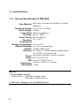
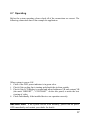
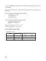
About This Manual
Welcome to the PMI-3000 series of industrial MMI panel PCs. This manual will
introduce the PMI-3000 series to you in very detail. In addition, It will help you
understand how to set up and use the PCs.
This manual contents two chapters and two appendixes.
Chapter 1
gives you an overview of the panel PCs.
Chapter 2
tells you how they are basically constructed and what
procedures
you should take for system setup.
Appendix A
gives detailed specifications of power supply.
Appendix B
gives a picture of exploded diagram on them.
Important Safety Instructions
n Please read this manual thoroughly before operating the unit and retain it for
future reference.
n Before you start any of the actions, be sure that you have the correct version
of the unit. So far the series have PMI-3000 and PMI-3000T.
n Unplug this product from the wall outlet before cleaning. If the surface of the
LCD cells needs to be cleaned, wipe it swiftly with cotton or other soft cloth.
If still not completely clear, blow on its surface and wipe.
n Since the front panel polarizer is easily damaged. Please pay attention not to
scratch on its face.
n Do not use this product near water. And avoid exposing this product to the
direct sunlight, strong ultraviolet light, etc. for a long time.
n This product should be operated from the type of power source specified. If
you are not sure which type of power source is available, please refer to
appendix A.
1
Packing List
Then you should also check if the package contains the following items. You
should contact your dealer immediately if any of these items are missing or
damaged:
n
n
n
n
n
2
One PMI-3000 industrial MMI panel PC with flat panel display
One power cord
A pack of accessory
PMI-3000 user’s manual
NOVA-300 user’s manual
Chapter 1 Overview
1.1 General
To fulfill customer satisfaction, we deeply concerned about quality, reliability, and
cost. The PMI-3000 series are specially designed to keep normal operation under
harsh environment which meet all the requirements for an industrial man-machine
interface. They are very tiny, thin, light, and convenient to install.
They come equipped with a flat panel display which is 9.4” color DSTN LCD, an
analog resistive touchscreen, an all-in-one 386 SBC, a universal 55W switching
power supply (refer to appendix A for options), a space for a 2.5” HDD, etc. All
of them are enclosed with a heavy-duty steel chassis and a high-quality plastic
front panel which meet the NEMA 4/12 industrial and environmental protection
standards.
All the controls and connectors are placed on the rear panel, you can connect the
panel PCs to other devices via them.
NOTE
Touchscreen or DC power supply is optional as your order and to ask
for additional price table.
1.1.1 The Single Board Computers (SBC)
The SBC contents a 386SX CPU with an on-board 2MB and up to 32MB,
local-bus SVGA controller. Its features include four 16C550 RS-232C ports, one
RS-232C port can be set RS-422/485 also, an enhanced IDE hard disk interface, a
floppy disk interface, one 32-pin sockets, watchdog timer, and a 6-pin Mini-Din
connector or 5 pin header for keyboard connector. Please refer to NOVA-300
user’s manual for more details about the SBC.
3
1.1.2
AS-40 (option)
We also have developed an external 3.5” FDD for you to choose among all the
third party FDDs. And your order number is AS-40.
4
1.2 Features
Motherboard:
–HM86508 LCD/CRT display controller
–4 serial ports of RS-232 and one selective RS-232/422/485
–All-in-one 386 SBC (386SX CPU & 1MB DRAM)
l Compact size 9.4” color DSTN LCD display
l Universal 55W switching power supply (or other options)
l Analog resistive or capacitive touchscreen (option)
l Heavy-duty steel chassis and NEMA 4/12 plastic front panel
l Panel mount
l 55mm deep only
l 30CFM cooling fan
l Space for a 2.5” HDD
l LED power indicator on the front panel
l Controls and connectors on the rear panel: brightness VR, keyboard, COM1,
printer port, contrast, PS/2 mouse, external FDD, COM2, COM3, COM4,
VGA
l
5
1.3 Specifications
1.3.1 General Specification of PMI-3000
Case Material Heavy-duty steel chassis & NEMA 4/12 plastic
front panel
Operating Voltage 85-265 VAC, 47-440Hz
Power Supply 55 Watts
Front Panel LED power indicator
Disk Bay One 2.5“ HDD
Inner Cooling One 30-CFM fan
Operating 0°C to 50°C
Temperature
Storage Temperature -20°C to 60°C
Relative Humidity 5 to 95%, non-condensing
Altitude 10,000ft (3000 meters)
Vibration 5 to 17Hz, 0.1” double-amplitude displacement
17 to 500Hz, 1.5G peak to peak
Shock 10G-peak acceleration (11-msec. duration)
Safety meets UL/CSA/TUV
EMI meets FCC/VDE Class A
Dimensions 316 (W) x 242 (H) x 55 (D) mm
Net Weight 3.5 Kgs
NOTE
1. Model Number System
Product Name
PMI-3000: standard model
PMI-3000T: with touchscreen
2. The colors of display is 16 in PMI-3000 series.
6
1.3.2 Display Specification
Display Base Model
Display Size
Active Area
Number Of Dots
Pixel Arrangement
Dot Size
Dot Pitch
Dimensions
Viewing Angle
(Contrast Ratio ≧ 5:1)
Response Time
Contrast Ratio
Luminance
Supply Voltage
Backlight
Weight
HITACHI, LMG9200XUCC
9.4” Diagonal
192(H) x 144(V) mm
640 x 3 (R,G,G) (W) x 480 (H) dots
RGB vertical stripe
0.070(W) x 0.270(H) mm
0.100(W) x 0.300(H) mm
243.0(W) x 179.0(H) x 9.0 max. (D) mm
Within 45 degrees from the vertical line to
the center of LCD
160ms (TYP.), “black” to “white”
20 (TYP.)
70cd/m2 (TYP.)
5±0.25V
Cold fluorescent lamp x 1
470 g (TYP.)
7
1.4 Dimensions
Unit: mm
8
Chapter 2 System Setup And Operating
2.1 General
This chapter prepares you for your first steps to know the PMI-3000 series
basically constructions. You will learn how to setup this system and your
applications step by step. Follow the steps presented in each section to install a
PC/104 daughter if you need, a 2.5” hard disk drive, and to mount it onto a panel.
As regards quality, you can make assurance doubly sure because we have set
them up and tested them at our factory before they were shipped.
IMPORTANT
Do not plug in any power when you start to setup the
system. Also remember whenever you want to open the panel PCs again for either
upgrading or maintenance you have to switch all the power off and unplug them.
9
2.2 Opening The Rear Cover
The rear cover is fastened to the chassis with two screws on the right and two
stoppers on the left. To open it you need only to unfasten the two screws and
draw the cover out under the stoppers.
NOTE
Notice that the hard disk drive housing and the PC/104 module are
occupying the same place.
10
2.3 The Hard Disk Drive
When you open the rear cover, you will see a plate is standing on four standoffs
from the SBC.
To install a 2.5” HDD
1. Take off the plate by unfastening four screws around it. Notice that you
needn’t take off the four standoffs.
2.Fix your HDD by four screws on the plate (as shown in the following figure).
3.Connect the HDD and SBC with a cable which attached in the accessory.
4.Mount the plat and disk onto SBC.
11
2.4 PC/104 Module
We said in section 2.2 that you need to take off the HDD when you want to install
a PC/104 module on the SBC.
To install a PC/104 module
1.Take off the HDD if you had installed a HDD.
2.Mount your PC/104 module onto SBC by fasten four screws (see the figure).
12
2.5 Panel Mounting
The panel PCs can be mounted onto a control panel within an aperture (see the
dimensions in section 1.4 ).
To mount the panel PC
1. Set the chassis within the aperture.
2. Slide the mounting kits into the slots on the top and bottom of the chassis.
3. Drive the screws on the kits tight against the control panel until a hooklike
click on the kits firmly stuck.
13
2.6 Connectors On The Rear Panel
The panel PCs have various connectors placed on rear panel, you can connect
them to various devices such as monitor, keyboard, mouse, floppy disk drive,
printer etc.
14
2.6.1 External VGA Monitor Connector
Uses a 15 pins female miniature D-SUB connector for connecting an external
CRT color monitor to the unit as a simultaneously display function. The external
monitor is software controlled, and can be displayed at 640 x 480 resolution with
16 colors.
2.6.2 Keyboard Connector
It is a rounded DIN connector (the mark “KEYBOARD” on the rear panel). Align
your keyboard DIN connector to the receptacle and gently plug into the unit.
The SBC’s BIOS standard setup menu allows you to select “All, But Keyboard”
under the “Halt On” selection. This allows no-keyboard operation in embedded
system applications without the system halting under POST (power-on-self-test).
2.6.3 PS/2 Mouse Connector (Option)
One PS/2 standard mouse port (the mark “PS/2 MOUSE” on the rear panel) with
the proper software driver installed will allow the operation of the PS/2 standard
mouse.
2.6.4 Floppy Drive Connector
You can attach one 3.5” FDD to the unit on the D-SUB 25 pins connector (the
mark “EXT. FDD” on the rear panel). We offer AS-40 for 3.5” FDD of your
option.
15
2.6.5 Printer Port Connector
One PC standard parallel port with a DB-25 female connector (the mark
“PRINTER PORT” on the rear panel) is available on the unit. Normally, the
parallel port of SBC is used to connect a printer. The default setting of the parallel
port is LPT1, IRQ7, and it also can be disabled in the system BIOS setup or
settings changed by rearranging the jumper block on the SBC.
2.6.6 Serial Ports Connector
The other three serial ports (the mark “COM1”, “COM2”, “COM3” “COM4”
on the rear panel) let you connect to serial devices (i.e. mouse, serial printer,
modem, scanner, etc.) or a communication network.
2.6.7 Power Inlet And Power Switch
This product is designed to accept the worldwide AC power source from 85VAC
to 265VAC at 47Hz to 440Hz. The power inlet provides an easy connection to the
AC power outlet via power cord, and the power switch controls the system ON
and OFF status.
To turn the system power ON or OFF
n Depress the power switch’s “0” end to make the system in the OFF
status.
n Depress the power switch’s “1” end to make the system in the ON status.
To connect the power cord to the power inlet
1. Depress the power switch to the “0” position.
2. Check the line voltage if its range is within specifications.
3. Match the letter (the mark “FG”, “N”, “L” on the rear panel) to the lines
of power cord and fix it with a screwdriver.
4. The system is ready to work now.
16
2.7 Operating
Before the system operating, please check all of the connections are correct. The
following connection chart is an example for application.
When system is power ON
1. Check if the LED power indicator is in green color.
2. Check if the cooling fan is turning and absorb the air from outside.
3. Check if the LCD display is normal and adjust brightness VR and contrast VR
(the mark “BRIGHT.”, “CONTRAST” on the rear panel) to make the best
viewing of video.
4. Check individually if the installed devices are operation correctly.
IMPORTANT
If the system can not work normally, please turn the power
OFF immediately and contact your dealer for details.
17
2.7.1 Touchscreen (option)
If the display of this product with touchscreen then the accessories include a
user’s manual, drivers, and a pen for touchscreen.
To work the touchscreen function
1. You should setup the software in advance. Please refer to the user’s manual
of touchscreen.
2. Use the pen to calibrate and use the pen or a finger to operate touch function.
NOTE
The surface of touch panel is a layer of transparent conductor. The
touch panel works by applying a voltage gradient across the conductive layer and
measuring the voltage at the point of contact with the opposing conductive layer.
So please avoid using hard object to scratch on its face.
18
Appendix A: Power Supply Specification
Power supply constitutes an essential part of the panel PCs, so we make this
section to let you know more about the power supply used in them. It is a
universal 55W AC switching power supply (default).
Industrial Features:
l 47- 440Hz input frequency
l 100% equipped “NIPPON CHEMI-CON” super high reliability aluminum
electrolytic capacitors
l 60KHz switching frequency control IC inside
l -20℃to 70℃ operating temperature
l High precision and stable DC outputs for long term operation
General Specifications:
Ripple and Noise: The peak to peak ripple and noise for each output is less than
1% at rated load. Measuring is done by 15MHz band width limited oscilloscope
and terminated at each output with a 0.47 uF capacitor.
Line Regulation: The line regulation for each output is less than +/-1% while
measuring at rated load and +/-10% of input voltage changing.
Load regulation: The output voltage load regulation is less than the values in the
following table by changing each output load +/-40% from 60% rated load, and
keep all other outputs at 60% rated load.
Output # +5V: +/-3% +12V: +/-5%
Hold-up Time: Hold-up time is longer then 16ms by measuring from the last AC
line changing pulse to the point that +5V drop down to +4.75V
Output Protection: The built-in over voltage protection circuit will shut down the
outputs to prevent damaging external circuits. The trip point of crowbar circuit is
around 5.9V to 7.0V. The power supply will go into latch off against short circuit
19
or over load conditions, and will have to OFF and ON the input line to restart the
power supply.
Efficiency: The efficiency is higher than 70% by measuring at normal line and
rated load.
Safety: Designed to meet the following standards
UL 478, 1012, 1950 D3
TUV EN60 950
CSA 22.2 No. 234
EMI: Designed to meet the following standards
FCC docket 20780 curve “B”
EN50081-2: CISPP22 “B”
Operating Temperature: -20℃ to 70℃
Storage Temperature: -30℃ to 85℃
Power Supply Selection Table
Output spec. at 50℃
20
Model
Input voltage
Universal/55W
24VDC/55W
12VDC/45W
85-265VAC
16-32VDC
9.5-18VDC
Max. Output Current
+5V
+12V
8A
1.2A
8A
1.2A
6A
1.1A
Appendix B: Exploded diagram
21
Table
Of
Contents
About This Manual ......................................................1
Important Safety Instructions.......................................................... 1
Packing List ........................................................................................ 2
Chapter 1 Overview .....................................................3
1.1 General .......................................................................................... 3
1.1.1 The Single Board Computers (SBC)..............................................3
1.1.2 AS-40...........................................................................................4
1.2 Features ........................................................................................ 5
1.3 Specifications............................................................................... 6
1.3.1 General Specification of PMI-3000 ................................................6
1.3.2 Display Specification.....................................................................7
Chapter 2 System Setup And Operating.....................9
2.1 General .......................................................................................... 9
2.2 Opening The Rear Cover .........................................................10
2.3 The Hard Disk Drive..................................................................11
2.4 PC/104 Module ...........................................................................12
2.5 Cleaning and changing the
fan ……………………………………..13
2.6 Panel Mounting..........................................................................14
2.6.1 External VGA Monitor Connector................................................15
2.6.2 Keyboard Connector...................................................................15
2.6.3 PS/2 Mouse Connector ...............................................................15
2.6.4 Floppy Drive Connector..............................................................15
2.6.5 Printer Port Connector ................................................................16
2.6.6 Serial Ports Connector ................................................................16
2.6.7 Power Inlet And Power Switch....................................................16
2.7 Operating ....................................................................................17
2.7.1 Touchscreen (option) ..................................................................18
Appendix A: Power Supply Specification.................19
Appendix B: Exploded diagram ................................21
USER’S
MANUAL
AMB-3000 Series
Industrial
MMI Panel PCs