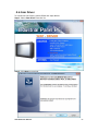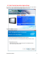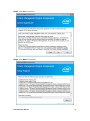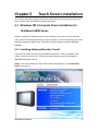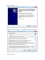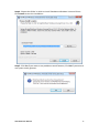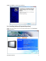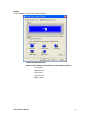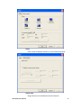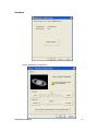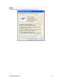
1
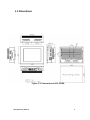
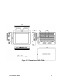
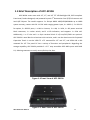
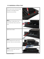
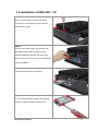
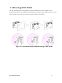
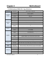
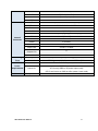
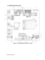
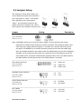
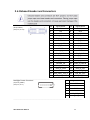
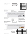
APC-3X19A 15”, 17”, and 19” 4th Gen. Intel Core i7/i5/i3 Panel PC User Manual Release Date Revision Oct. 2015 V1.0 ®2015 Aplex Technology, Inc. All Rights Reserved. Published in Taiwan Aplex Technology, Inc. 15F-1, No.186, Jian Yi Road, Zhonghe District, New Taipei City 235, Taiwan Tel: 886-2-82262881 Fax: 886-2-82262883 E-mail: [email protected] URL: www.aplextec.com APC-3X19A User Manual 0 Revision History Reversion Date Description 1.0 2015/10/06 Official Version APC-3X19A User Manual 1 Warning!___________________________ This equipment generates, uses and can radiate radio frequency energy and if not installed and used in accordance with the instructions manual, it may cause interference to radio communications. It has been tested and found to comply with the limits for a Class A computing device pursuant to FCC Rules, which are designed to provide reasonable protection against such interference when operated in a commercial environment. Operation of this equipment in a residential area is likely to cause interference in which case the user at his own expense will be required to take whatever measures may be required to correct the interference. Electric Shock Hazard – Do not operate the machine with its back cover removed. There are dangerous high voltages inside. Caution Risk of explosion if the battery is replaced with an incorrect type. Batteries should be recycled where possible. Disposal of used batteries must be in accordance with local environmental regulations. APC-3X19A User Manual 2 Packing List Accessories (as ticked) included in this package are: □ Adaptor □ Driver & manual CD disc □ Other.___________________(please specify) Safety Precautions Follow the messages below to prevent your systems from damage: ◆ Avoid your system from static electricity on all occasions. ◆ Prevent electric shock. Don‘t touch any components of this card when the card is power-on. Always disconnect power when the system is not in use. ◆ Disconnect power when you change any hardware devices. For instance, when you connect a jumper or install any cards, a surge of power may damage the electronic components or the whole system. APC-3X19A User Manual 3 Table of Contents Revision History…………………………………………………………………………………………….1 Warning!/Caution………………..................................…………………………….……..….2 Packing List/Safety Precautions.....………………………………………………………………..3 Chapter 1 Getting Started 1.1 Features……………….……………………………………...………………………………….6 1.2 Specifications…………………………………………………………………………………...6 1.3 Dimensions…………………………………..………………………...………………….......8 1.4 Brief Description of APC-3X19A..………………………………………………..……11 1.5 Installation of Riser Card………………………………………………………………….12 1.6 Installation of HDD/SSD – 15”………………………………………………………….13 1.7 Installation of HDD/SSD – 17” and 19”..…………………………………………..14 1.8 Mounting of APC-3X19A………………………………………………………………….15 Chapter 2 Motherboard 2.1 Motherboard IMB-181-L Specifications…………….………..………………..…16 2.2 Motherboard Layout..……….....…………………….……………...……………….…18 2.3 I/O Panel……………………………………………….………………………………………..20 2.4 Installation……………………………………………………..……………………………….21 2.5 Jumpers Setup………………………………………………………………………………...24 2.6 Onboard Headers and Connectors……………………………………………….….25 Chapter 3 UEFI SETUP UTILITY 3.1 Introduction………………………………....………………….………..………………..…30 3.2 Main Screen..…………………….....…………………….……………...……………….…31 3.3 Advanced Screen……………………...........................................................32 3.4 Hardware Health Event Monitoring Screen….………………………………….45 3.5 Boot Screen………………………………………………………..……..……………………46 3.6 Security Screen………………………………………………………………………….…….48 3.7 Exit Screen………………………………………………………………………………..…....48 Chapter 4 Installation of Drivers 4.1 Intel Q87 Chipset Driver………………….…..………………………………………….51 4.2 Intel® VGA Chipsrt Driver.....................................................................54 APC-3X19A User Manual 4 4.3 Intel I210 & I217LM LAN Driver…........................................................57 4.4 Rearltek_Audio Driver.........................................................................60 4.5 USB 3.0 Driver………………….……………………………………………………………..62 4.6 Com Driver….......................................................................................65 4.7 Intel Trusted Execution Engine Driver..................................................67 4.8 SmartConnect Driver……………………………………………………………………….69 Chapter 5 Touch Screen Installation 5.1 Windows 7/8.1 Universal Driver Installation for PenMount 6000 Series……………………………………………………………………………………………...73 5.2 Software Functions……………………………....……….………………………….……82 Figures Figure 1.1: Dimensions of APC-3519A…………………….…....………………..……...8 Figure 1.2: Dimensions of APC-3719A……………………………………………………..9 Figure 1.3: Dimensions of APC-3919A……………………………………………………10 Figure 1.4: Front View of APC-3X19A…....…….….....………………………………..11 Figure 1.5: Rear View of APC-3X19A…….……………………………………………....11 Figure 1.6: Panel Mounting and Wall Mounting of APC-3x19A………...……14 Figure 2.1: Motherboard Layout…………………………………………..……………….17 APC-3X19A User Manual 5 Chapter 1 Getting Started 1.1 Features 15”/17”/19” TFT LED Backlight LCD 4th Generation Intel Core i7/i5/i3 Panel PC Intel Q87 2 x DDR3 1066/1333/1600MHz SO-DIMM, up to 16GB System Memory Fanless Design Support 1 x PCIe x16 Wide range DC 11~32V Power Input IP65 Compliant Front Panel 1.2 Specifications APC-3519A APC-3719A APC-3919A System Processor System Chipset System Memory Storage OS Support Socket LGA 1150, 4th Gen. intel Core i7/i5/i3 Intel Core i7-4770TE 2.3G 8M (TDP: 45W) Intel Core i5-4570TE 2.7G 4M(TDP: 35W) Intel Core i3-4330TE 2.4G 4M(TDP: 35W) Intel Q87 2 x 204-pin DDR3 SO-DIMM, up to 16GB 1066/1333/1600MHz 2 x 2.5” SATA HDD Space, Easy Accessible, RAID 0.1 Windows 7 Professional for Embedded Systems Windows 7 Ultimate for Embedded Systems Windows Embedded 8.1 Pro Windows 8.1 Industry pro I/O Ports USB Serial/Parallel Audio LAN VGA Power Others APC-3X19A User Manual 4 x USB 3.0 Type A 2 x USB 2.0 Type A by cable (option) 3 x RS-232/422/485 DB-9, COM1, COM2, and COM3, Default RS-232 1 x Mic-in, Line-out 2 x GbE LAN RJ-45 1 x VGA 1 x DC Power 3-pin Terminal Block Connector 1 x Rocker Switch for Power on/off 2 x LED Indication for Power and HDD 1 x 8-pin Terminal Block 3 in/3 out/VCC/GND (option) 1 x CF Slot (option) 6 Expansion Slots Expansion Slots Power Power Input Power Consumption LCD Display Type Max. Resolution Max. Color Contrast Ratio Luminance (cd/m2) Viewing Angle Backlight Lifetime Touch Screen(option) Type Interface Light Transmission 1 x PCIe x16 slot 1 x mSATA or 1 x Mini-PCIe slot for WIFI/BT/3G/GPS (option) MAX: 45.1W 11~32V DC MAX: 48.5W MAX: 51.2W 15” color TFT LCD 1024 x 768 16.7M 800: 1 400 160 (H) / 140 (V) 50,000 hrs 17” color TFT LCD 1280 x 1024 16.7M 1000: 1 350 170 (H) / 160 (V) 30,000 hrs 19” color TFT LCD 1280 x 1024 16.7M 1000: 1 350 170 (H) / 160 (V) 50,000 hrs Resistive Touch Screen/Projected Capacitive Touch Screen USB Over 80%(Resistive) Over 90%(Projected Capacitive) Mechanical Front Bezel Rear Bezel Mounting IP Rating Dimension Net Weight Environmental Operating Temperature Storage Temperature Storage Humidity Certificate APC-3X19A User Manual Steel Black or Aluminum with Resistive Touch Aluminum with Projected Capacitive Touch (only Flat Bezel Designed) Steel Black Panel Mount/VESA Panel Mount/VESA Mount 75 x 75 Mount 100 x 100 IP65 Compliant Front Panel 410 x 310 x 122.5mm 439 x 348 x 119.1mm 484 x 400 x 119mm 9.5Kg 10.8Kg 12.9Kg 0~50 °C -30~70 °C 10%~90%@ 40℃, non-condensing Meet CE / FCC Class A 7 1.3 Dimentions Figure 1.1: Dimensions of APC-3519A APC-3X19A User Manual 8 Figure 1.2: Dimensions of APC-3719A APC-3X19A User Manual 9 Figure 1.3: Dimensions of APC-3919A APC-3X19A User Manual 10 1.4 Brief Description of APC-3X19A APC-3X19A series come with 15”, 17”, and 19” TFT LED Backlight LCD, IP65 compliant Front bezel, fanless designed, and powered by Intel 4th Generation Core i7/i5/i3 Processor and Intel Q87 Chipset. The model supports 2 x 204-pin DDR3 1066/1333/1600MHz up to 16GB system memory, comes with DC 11~32V wide-ranging power input, 4 x USB 3.0, 2 x USB 2.0 for option, 3 x RS-232 ports, 1 x Mic-in Line-out, 2 x LAN, 1 x VGA, 1 x DC power terminal block connector, 1 x rocker switch, and 2 x LED indication, and supports 1 x PCIe x16. Additionally, 1 x CF slot and 1 x 8-pin terminal block 3 in/3 out/VCC/GND are optional. APC-3X19A is steel black or aluminum with resistive, and it can be aluminum with Projected Capacitive Touch. It can be VESA 75 x 75 mounted for 15” and 17”, and VESA 100 x 100 mounted for 19”. The panel PC has a variety of functions and peripherals. Regarding the storage capability, APC-3X19A provides 2 x 2.5” easy accessible SATA HDD space with RAID 0.1, allowing customers to easily access/backup the data. Figure 1.4 Front View of APC-3X19A Figure 1.5: Rear View of APC-3X19A APC-3X19A User Manual 11 1.5 Installation of Riser Card Step 1 There are two screws to deal with when enclosing or removing the chassis. Gently remove two screws. Step 2 In the picture, it shows there is one screw to deal with. Gently remove the screw. Step 3 Pull out the iron sheet. Step 4 You can replace the riser card on the iron sheet. Then Put it into the chassis. Step 5 This is how it looks after riser card is installed correctly. APC-3X19A User Manual 12 1.6 Installation of HDD/SSD – 15” Step 1 There are two screws to deal with when enclosing or removing the chassis. Gently remove two screws. Step 2 Take off the chassis cover and you will see two HDD bracket. Both of them can be installed HDD/SSD through the same way. Remove the screw by hand. User screwdriver is also acceptable. Step 3 Pull the HDD bracket out carefully. Step 4 You can replace HDD or SSD by unscrewing the four screws as shown in the picture. APC-3X19A User Manual 13 1.7 Installation of HDD/SSD – 17” and 19” Step 1 There are two screws to deal with when enclosing or removing the chassis. Gently remove two screws. Step 2 Take off the chassis cover and you will see two HDD bracket. Both of them can be installed HDD/SSD through the same way. Unscrew the screws Step 3 Pull the bracket out carefully. You can replace HDD or SSD by unscrewing the two screws as shown in the picture. APC-3X19A User Manual 14 1.8 Mounting of APC-3X19A The APC-3X19A panel PC is designed to be panel-mounted as shown in Figure 1.6 just carefully place the unit through the hole and tighten the given screws from the rear to secure the mounting. And it also can be wall mounted as shown in the figure. Figure 1.6: Panel Mounting and Wall Mounting of APC-3x19A APC-3X19A User Manual 15 Chapter 2 Motherboard 2.1 Motherboard IMB-181-L Specifications Form Factor Processor System Expansion Slot Memory Graphics Ethernet SATA Rear I/O Dimensions CPU Core Number Max Speed L3 Cache Chipset BIOS PCI Mini-PCI3 mSATA PCIe CFast Card Socket Technology Max. Socket Controller VRAM Mini-ITX(6.7-in x 6.7-in) Socket LGA1150 for Intel® Core i7/i5/i3/Celeron (Haswell) (By CPU, Max 4) (By CPU) (By CPU) Q87 UEFI 0 1 (full size) shared with m-SATA 1 (shared with mini-PCIe) 1 (x16) 0 Dual Channel DDR3 1066/1333/1600 MHz SDRAM 16GB 2 x SO-DIMM Intel® HD Graphics (By CPU) Shared Memory VGA Supports max resolution 2048 x 1536 LVDS Yes HDMI Supports HDMI 1.4a, max resolution 1920 x 1200 DVI Display Port No No Multi Display Yes (Three Display) Ethernet Controller Connector Max Data Transfer Rate VGA DVI HDMI Display Port Ethernet 10/100/1000 Mbps GbE LAN1: Intel® I210, LAN2: Intel® I217LM (with v-Pro support) 2 x RJ-45 APC-3X19A User Manual SATA2 (3.0Gb/S), SATA3 (6.0Gb/S), Supports RAID 0/1/5/10 1 0 1 0 2 16 Internal Connector Watchdog Timer USB Audio Serial PS/2 USB LVDS/Inverter VGA Serial SATA mPCIe Parallel mSATA IrDA GPIO 8-bit SATA PWR Output Con Speaker Header Output Interval Input PWR Power Requirements Power On Environment Temperature APC-3X19A User Manual 4 x USB 3.0 compliant 2 (Mic-in, Line-Out) 3 (RS-232/422/485) 0 8 (4 x USB Header 2.54mm pitch) 24 bit dual channel LVDS 0 4 (RS-232) 4 x SATA3 (6.0Gb/s), Support RAID 0/1/5/10 1 (shared) 0 1 (shared) 0 4 x GPI + 4 x GPO 0 1 Output from super I/O to drag RESETCON# 256 Segments, 0, 1, 2, ………………255 Sec/Min ATX PWR (4 + 24) AT/ATX Supported -AT: Directly PWR on as power input ready -ATX: Press button to PWR on after power input ready 0~60 °C 17 2.2 Motherboard Layout Figure 1.11: Motherboard IMB-181-L Layout APC-3X19A User Manual 18 1*: Backlight Power Connector 2*: Backlight Volume Control 3*: 24-pin ATX Power Input Connector 4*: PNL_PWR1 5*: Backlight Power Selection 6*: BLT_PWM1 7*: PS2_KB_MS1 8*: RS-232 Port 4 Pint Headers 9*: 4-Pin Chassis FAN Connector (+12V) 10: Chassis Intrusion Headers 11: 4-pin ATX Power Input Connector 12: TPM Header 13: System Panel Header 14*: 3W Audio AMP Output Wafer 15: Digital Input/Output Pin Header 16: 4-Pin Chassis FAN Connector (+12V) 17: Clear CMOS Header 18: ATX/AT Mode Jumper 19*: SATA3 Connectors (SATA_0, SATA_1, SATA_4, SATA_5) (SATA_5 (orange) is shared with mini-PCIe/mini-SATA slot) 20: Front Panel Audio Header 21*: USB 2.0 Connectors 22*: LVDS Panel Connector APC-3X19A User Manual 19 2.3 I/O Panel 1. 2. 3. 4. 5. 6. COM Port (COM1) COM Port (COM3) LAN RJ-45 Port (LAN1) LAN RJ-45 Port (LAN2) Line out (Lime) Microphone (Pink) 7. USB 3.0 Ports (USB_23) 8. USB 3.0 Ports (USB_01) 9. VGA Port (VGA1) 10. COM Port (COM2) 11. HDMI Port (HDMI1) *There are two LED next to the LAN port. Please refer to the table below for the LAN port LED indications. LAN Port LED Indications Activity/Link LED SPEED LED Status Description Status Description Off No Link Off 10Mbps connection Blinking Data Activity Orange 100Mbps connection On Link Green 1Gbps Connection APC-3X19A User Manual 20 2.4 Installation This is a Mini-ITX form factor (6.7" x 6.7", 17.0 x 17.0 cm) motherboard. Before you install the motherboard, study the configuration of your chassis to ensure that the motherboard fits into it. 2.4.1 Screw Holes Place screws into the holes to secure the motherboard to the chassis. 2.4.2 Pre-installation precautions Take note of the following precautions before you install motherboard components or change any motherboard settings. 1. Unplug the power cord from the wall socket before touching any component. 2. To avoid damaging the motherboard components due to static electricity, NEVER place your motherboard directly on the carpet or the like. Also remember to use a grounded wrist strap or touch a safety grounded object before you handle components. 3. Hold components by the edges and do not touch the ICs. 4. Whenever you uninstall any component, place it on a grounded antistatic pad or in the bag that comes with the component. APC-3X19A User Manual 21 2.4.3 Installation of Memory Modules (SO-DIMM) This motherboard provides two 204-pin DDR3 (Double Data Rate 3) SO-DIMM slots. Installing a SO-DIMM Step 1. Unlock a SO-DIMM slot by pressing the retaining clips outward. Step 2. Align a SO-DIMM on the slot such that the notch on the SO-DIMM matches the break on the slot. Step 3. Firmly insert the SO-DIMM into the slot until the retaining clips at both ends fully snap back in place and the SO-DIMM is properly seated. APC-3X19A User Manual 22 2.4.4 Expansion Slots (PCI Express and mini-PCIe/mini-SATA Slots) There is 1 PCI Express slot and 1 mini-PCIe/mini-SATA slot on this motherboard. PCIE slots: PCIE1 (PCIE x16 slot, Blue) is used for PCI Express x16 lane width graphics cards. MINI_PCIE1 (mini-PCIe/mini-SATA slot) is used for PCI Express mini cards or mSATA cards. Installing an expansion card Step 1. Before installing the expansion card, please make sure that the power supply is switched off or the power cord is unplugged. Please read the documentation of the expansion card and make necessary hardware settings for the card before you start the installation. Step 2. Remove the system unit cover (if your motherboard is already installed in a chassis). Step 3. Remove the bracket facing the slot that you intend to use. Keep the screws for later use. Step 4. Align the card connector with the slot and press firmly until the card is completely seated on the slot. Step 5. Fasten the card to the chassis with screws. Step 6. Replace the system cover. APC-3X19A User Manual 23 2.5 Jumpers Setup The illustration shows how jumpers are setup. When the jumper cap is placed on pins, the jumper is “Short”. If no jumper cap is placed on pins, the jumper is “Open”. The illustration shows a 3-pin jumper whose pin1 and pin2 are “Short” when jumper cap is placed on these 2 pins. Jumper Setting Description Clear CMOS Jumper (3-pin CLRCMOS1) (see p.12, No. 17) Note: CLRCMOS1 allows you to clear the data in CMOS. To clear and reset the system parameters to default setup, please turn off the computer and unplug the power cord from the power supply. After waiting for 15 seconds, use a jumper cap to short pin2 and pin3 on CLRCMOS1 for 5 seconds. However, please do not clear the CMOS right after you update the BIOS. If you need to clear the CMOS when you just finish updating the BIOS, you must boot up the system first, and then shut it down before you do the clear-CMOS action. Please be noted that the password, date, time, user default profile and MAC address will be cleared only if the CMOS battery is removed. ____________________________________________________________________________ Panel Power Selection 1-2: LVDD: +3V (5-pin PNL_PWR1) (see p.12, No. 4) 2-3: 4-5: LVDD: +5V LVDD: +12V ____________________________________________________________________________ Backlight Power Selection 1-2: +5V (3-pin BKT _PWR1) (see p.12, No. 5) 2-3: +12V ____________________________________________________________________________ ATX/AT Mode Selection 1-2: AT Mode (3-pin PWR_JP1) (see p.12, No. 18) 2-3: ATX Mode ____________________________________________________________________________ BLT_PWM1 1-2: +3V Level (3-pin BLT_PWM1) (see p.12, No. 6) APC-3X19A User Manual 2-3: +5V Level 24 2.6 Onboard Header and Connectors LVDS Panel Connector (40-pin LVDS1) (see p.12, No. 22) PIN Signal Name PIN Signal Name 1 LVDD 2 LVDD 3 +3V 4 N/A 5 N/A 6 LVDS_A_DATA0# 7 LVDS_A_DATA0 8 GND1 9 LVDS_A_DATA1# 10 LVDS_A_DATA1 11 GND6 12 LVDS_A_DATA2# 13 LVDS_A_DATA2 14 GND2 15 LVDS_A_DATA3# 16 LVDS_A_DATA3 17 GND7 18 LVDS_A_CLK# 19 LVDS_A_CLK 20 GND3 21 LVDS_B_DATA0# 22 LVDS_B_DATA0 23 GND8 24 LVDS_B_DATA1# 25 LVDS_B_DATA1 26 GND4 27 LVDS_B_DATA2# 28 LVDS_B_DATA2 29 DPLVDD_EN 30 LVDS_B_DATA3# 31 LVDS_B_DATA3 32 GND5 33 LVDS_B_CLK# 34 LVDS_B_CLK 35 GND9 36 CON_LBKLT_EN_R 37 CON_LBKLT_CTR_R 38 LCD_BLT_VCC 39 LCD_BLT_VCC 40 LCD_BLT_VCC ______________________________________________________________________________________________________________________________________________________________________________________ Backlight Power Connector (6-pin BLT_PWR1) (see p.12, No. 1) PIN 1 2 3 4 5 6 Signal Name GND GND BL EN BL CTL LCD_BLT_VCC LCD_BLT_VCC ______________________________________________________________________________________________________________________________________________________________________________________ APC-3X19A User Manual 25 Backlight Volume Control PIN 1 2 3 4 5 6 7 (7-pin BLT_VOL1) (see p.12, No. 2) Signal Name GPIO_VOL_UP GPIO_VOL_DW PWRDN LVDS1 BLUP LVDS1 BLDW GND GND ______________________________________________________________________________________________________________________________________________________________________________________ CPU Fan Connector Please connect the CPU fan cable to the connector and match the black wire to the ground pin. (4-pin CPU_FAN1) (see p.12, No. 9) ______________________________________________________________________________________________________________________________________________________________________________________ Chassis Fan Connector Please connect the fan cable to the fan connector and match the black wire to the ground pin. (4-pin CHA_FAN1) (see p.12, No. 16) ______________________________________________________________________________________________________________________________________________________________________________________ ATX Power Input Connector Please connect an ATX power supply to this connector. (24-pin ATXPWR1) (see p.12. No. 3) ______________________________________________________________________________________________________________________________________________________________________________________ 8: COM4, 5, 6 Headers (RS232) (9-pin COM4/COM5/COM6: see p.12, No. 8) APC-3X19A User Manual PIN 2 4 6 8 10 Signal Name RRXD1 DDTR#1 DDSR#1 CCTS#1 NC PIN 1 3 5 7 9 Signal Name DDCD#1 TTXD1 GND RRTS#1 COM PWR 26 ______________________________________________________________________________________________________________________________________________________________________________________ Digital Input/Output Pin Header (10-pin JGPIO1) (see p.12, No. 15) PIN 1 3 5 7 9 Signal Name SIO_GP24 SIO_GP25 SIO_GP26 SIO_GP27 JGPIO_PWR1 PIN 2 4 6 8 10 Signal Name SIO_GP20 SIO_GP21 SIO_GP22 SIO_GP23 GND ______________________________________________________________________________________________________________________________________________________________________________________ System Panel Header (9-pin PANEL1) (see p.12, No. 13) APC-3X19A User Manual This header accommodates several system front panel functions. 27 ______________________________________________________________________________________________________________________________________________________________________________________ SATA3 Connectors (SATA_0/SATA_1/SATA_4/SATA_5: see p.12, No. 19) SATA2 Connectors (SATA_4/SATA_5: see p.12, No. 19) These four Serial ATA3 (SATA3) connectors support SATA data cables for internal storage devices. The current SATA3 interface allows up to 6.0 Gb/s data transfer rate. (SATA_5 (orange) is shared with mini-PCIe/mini-SATA slot.) These two Serial ATA2 (SATA2) connectors support SATA data cables for internal storage devices. The current SATA2 interface allows up to 3.0 Gb/s data transfer rate. (SATA_5 (orange) is shared with mini-SATA slot.) _________________________________________________________________________________________________________________________________________________________________________ USB 2.0 Headers (9-pin USB4_5/USB6_7/USB8_9/USB10_11: see p.12, No. 21) There are four USB 2.0 headers on this motherboard. Each USB 2.0 header can support two USB 2.0 ports. _________________________________________________________________________________________________________________________________________________________________________ Chassis Intrusion Headers (2-pin Cl1/Cl2: see p.12, No. 10) This motherboard supports CASE OPEN detection feature that detects if the chassis cover has been removed. This feature requires a chassis with chassis intrusion detection design. Cl1: Close: Active case open Open: Normal Cl2: Close: Normal Open: Active case open _________________________________________________________________________________________________________________________________________________________________________ APC-3X19A User Manual 28 Front Panel Audio Header (9-pin HD_AUDIO1) (see p.12 No. 20) This is an interface for front panel audio cable that allows convenient connection and control of audio devices. _________________________________________________________________________________________________________________________________________________________________________ 3W Audio Amp Output Wafer (4-pin SPEAKER1) (see p.12, No. 14) PIN 1 2 3 4 Signal Name SPK LSPK L+ SPK R+ SPK R- _________________________________________________________________________________________________________________________________________________________________________ ATX 12V Power Input Connector (4-pin ATX12V1) (see p.12, No. 11) Please connect an ATX 12V power supply to this connector. _________________________________________________________________________________________________________________________________________________________________________ TPM Header (19-pin TPM1) (see p.12, No. 12) This connector supports a Trusted Platform Module (TPM) system, which can securely store keys, digital certificates, passwords, and data. A TPM system also helps enhance network security, projects digital identities, and ensures platform integrity. _________________________________________________________________________________________________________________________________________________________________________ PS2_KB_MS1 (8-pin PS2_KB_MS1) (see p.12, No. 7) APC-3X19A User Manual PIN 1 2 3 4 5 6 7 8 Signal Name KBCLK +5V KBDATQA +5V MSDATA GND MSCLK GND 29 Chapter 3 UEFI SETUP UTILITY 3.1 Introduction This section explains how to use the UEFI SETUP UTILITY to configure your system. The UEFI chip on the motherboard stores the UEFI SETUP UTILITY. You may run the UEFI SETUP UTILITY when you start up the computer. Please press <F2> or <Del> during the Power-On-Self-Test (POST) to enter the UEFI SETUP UTILITY, otherwise, POST will continue with its test routines. If you wish to enter the UEFI SETUP UTILITY after POST, restart the system by pressing <Ctl> + <Alt> + <Delete>, or by pressing the reset button on the system chassis. You may also restart by turning the system off and then back on. 3.1.1 UEFI Menu Bars The top of the screen has a menu bar with the following selections: Main To set up the system time/date information Advanced To set up the advanced UEFI features H/W Monitor To display current hardware status Boot To set up the default system device to locate and load the Operating System Security To set up the security features Exit To exit the current screen or the UEFI SETUP UTILITY Use <←> key or <→> key to choose among the selections on the menu bar, and then press <Enter> to get into the sub screen. You can also use the mouse to click your required item. APC-3X19A User Manual 30 3.1.2 Navigation Keys Please check the following table for the function description of each navigation key. Navigation key(s) Function Description ←/→ Moves cursor left or right to select Screen ↑/↓ Moves cursor up or down to select items +/To change option for the selected items <Enter> To bring up the selected screen <F1> To display the General Help Screen <F7> Discard changes <F9> To load optimal default values for all the settings <F10> To save changes and exit the UEFI SETUP UTILITY <F12> Print screen <ESC> To jump to the Exit Screen or exit the current screen 3.2 Main Screen When you enter the UEFI SETUP UTILITY, the Main screen will appear and display the system overview. APC-3X19A User Manual 31 3.3 Advanced Screen In this section, you may set the configurations for the following items: CPU Configuration, Chipset Configuration, Storage Configuration, Intel(R) Rapid Start Technology, Intel(R) Smart Connect Technology, AMT Configuration, Super IO Configuration, ACPI Configuration, USB Configuration and Voltage Configuration. Instant Flash Instant Flash is a UEFI flash utility embedded in Flash ROM. This convenient UEFI update tool allows you to update system UEFI without entering operating systems first like MS-DOS or Windows®. Just launch this tool and save the new UEFI file to your USB flash drive, floppy disk or hard drive, then you can update your UEFI only in a few clicks without preparing an additional floppy diskette or other complicated flash utility. Please be noted that the USB flash drive or hard drive must use FAT32/16/12 file system. If you execute Instant Flash utility, the utility will show the UEFI files and their respective information. Select the proper UEFI file to update your UEFI, and reboot your system after UEFI update process completes. APC-3X19A User Manual 32 3.3.1 CPU Configuration Intel Hyper Threading Technology Intel Hyper Threading Technology allows multiple threads to run on each core, so that the overall performance on threaded software is improved. Active Processor Cores Select the number of cores to enable in each processor package. CPU C States Support Enable CPU C States Support for power saving. It is recommended to keep C3, C6 and C7 all enabled for better power saving. Enhanced Halt State (C1E) Enable Enhanced Halt State (C1E) for lower power consumption. CPU C3 State Support Enable C3 sleep state for lower power consumption. CPU C6 State Support Enable C6 deep sleep state for lower power consumption. CPU C7 State Support Enable C7 deep sleep state for lower power consumption. Package C State Support Enable CPU, PCIe, Memory, Graphics C State Support for power saving. APC-3X19A User Manual 33 Intel SpeedStep Technology Intel SpeedStep technology is Intel’s new power saving technology. Processors can switch between multiple frequencies and voltage points to enable power saving. The default value is [Enabled]. Configuration options: [Enabled] and [Disabled]. If you install Windows® 7 / 8 and want to enable this function, please set this item to [Enabled]. This item will be hidden if the current CPU does not support Intel SpeedStep technology. Intel Turbo Boost Technology Use this item to enable or disable Intel Turbo Boost Mode Technology. Turbo Boost Mode allows processor cores to run faster than marked frequency in specific conditions. The default value is [Enabled]. CPU Thermal Throttling You may select [Enabled] to enable CPU internal thermal control mechanism to keep the CPU from overheating. No-Execute Memory Protection No-Execution (NX) Memory Protection Technology is an enhancement to the IA-32 Intel Architecture. An IA-32 processor with “No Execute (NX) Memory Protection” can prevent data pages from being used by malicious software to execute codes. This option will be hidden if the current CPU does not support No-Excute Memory Protection. Intel Virtualization Technology When this option is set to [Enabled], a VMM (Virtual Machine Architecture) can utilize the additional hardware capabilities provided by Vanderpool Technology. This option will be hidden if the installed CPU does not support Intel Virtualization Technology. Hardware Prefetcher Use this item to turn on/off the MLC streamer prefetcher. Adjacent Cache Line Prefetch Use this item to turn on/off prefetching of adjacent cache lines. APC-3X19A User Manual 34 3.3.2 Chipset Configuration DRAM Frequency If [Auto] is selected, the motherboard will detect the memory module(s) inserted and assign the appropriate frequency automatically. Primary Graphics Adapter This allows you to select [Onboard] or [PCI Express] as the boot graphic adapter priority. The default value is [PCI Express]. VT-d Use this to enable or disable Intel® VT-d technology (Intel® Virtualization Technology for Directed I/O). The default value of this feature is [Disabled]. PCIE1 Link Speed Select the link speed for PCIE1. Share Memory Configure the size of memory that is allocated to the integrated graphics processor when the system boots up. IGPU Multi-Monitor Select disable to disable the integrated graphics when an external graphics card is installed. Select enable to keep the integrated graphics enabled at all times. APC-3X19A User Manual 35 Render Standby Use this to enable or disable Render Standby by Internal Graphics Device. The default value is [Enabled]. Onboard HD Audio Select [Auto], [Enabled] or [Disabled] for the onboard HD Audio feature. If you select [Auto], the onboard HD Audio will be disabled when PCI Sound Card is plugged. Front Panel Select [Auto] or [Disabled] for the onboard HD Audio Front Panel. Onboard HDMI HD Audio This allows you to enable or disable the Onboard HDMI HD Audio feature. Onboard LAN1 This allows you to enable or disable the Onboard LAN1 feature. Onboard LAN2 This allows you to enable or disable the Onboard LAN2 feature. Deep Sleep Mobile platforms support Deep S4/S5 in DC only and desktop platforms support Deep S4/S5 in AC only. The default value is [Disabled]. Restore on AC/Power Loss This allows you to set the power state after an unexpected AC/power loss. If [Power Off] is selected, the AC/power remains off when the power recovers. If [Power On] is selected, the AC/power resumes and the system starts to boot up when the power recovers. Active LVDS Use this to enable or disable the LVDS. The default value is [Enabled]. Panel Type Selection Use this to select panel type. Primary IGFX Boot Display Select the Video Device which will be activated during POST. This has no effect if external graphics present. Secondary boot display selection will appear based on your selection. VGA modes will be supported only on primary display. Configuration options: [VBIOS Default], [CRT], [DVI], [HDMI] and [LVDS]. The default value is [VBIOS Default]. APC-3X19A User Manual 36 3.3.3 Storage Configuration SATA Controller(s) Use this item to enable or disable the SATA Controller feature. SATA Mode Selection Use this to select SATA mode. Configuration options: [IDE Mode], [AHCI Mode] and [RAID Mode]. The default value is [AHCI Mode]. SATA Aggressive Link Power Management Use this item to configure SATA Aggressive Link Power Management. Dynamic Storage Accelerator Keep this option enabled for higher HDD and SDD I/O performance, lower latency and increased system responsiveness. Hard Disk S.M.A.R.T. Use this item to enable or disable the S.M.A.R.T. (Self-Monitoring, Analysis, and Reporting Technology) feature. Configuration options: [Disabled] and [Enabled]. APC-3X19A User Manual 37 3.3.4 Intel® Rapid Start Technology Intel(R) Rapid Start Technology Use this item to enable or disable Intel(R) Rapid Start Technology. Intel(R) Rapid Start Technology is a new zero power hibernation mode which allows users to resume in just 5-6 seconds. The default is [Disabled]. APC-3X19A User Manual 38 3.3.5 Intel® Smart Connect Technology Intel(R) Smart Connect Technology Use this item to enable or disable Intel(R) Smart Connect Technology. Intel(R) Smart Connect Technology keeps your e-mail and social networks, such as Twitter, Facebook, etc. updated automatically while the computer is in sleep mode. The default is [Enabled]. 3.3.6 AMT Technology APC-3X19A User Manual 39 Intel AMT Use this to enable or disable Intel(R) Active Management Technology BIOS Extension. The default is [Enabled]. BIOS Hotkey Pressed Use this to enable or disable BIOS hotkey press. The default is [Disabled]. MEBx Selection Screen Use this to enable or disable MEBx Selection Screen. The default is [Disabled]. Hide Un-Configure ME Confirmation Hide Un-Configure ME without password confirmation prompt. The default is [Disabled]. MEBx Debug Message Output Use this to enable or disable MEBx Debug Message Output. The default is [Disabled]. Un-Configure ME Un-Configure ME without password. The default is [Disabled]. Amt Wait Timer Set timer to wait before sending ASF_GET_BOOT_OPTIONS. Disable ME Set ME to Soft Temporary Disabled. The default is [Disabled]. ASF Use this to enable or disable Alert Specification Format. The default is [Enabled]. Activate Remote Assistance Process Trigger CIRA boot. The default is [Disabled]. USB Configure Use this to enable or disable USB Configure function. The default is [Enabled]. PET Progress User can enable or disable PET Events progress to receive PET events or not. The default is [Enabled]. APC-3X19A User Manual 40 3.3.7 Super IO Configuration COM1 Configuration Use this to set parameters of COM1. COM2 Configuration Use this to set parameters of COM2. COM3 Configuration Use this to set parameters of COM3. COM4 Configuration Use this to set parameters of COM4. COM5 Configuration Use this to set parameters of COM5. COM6 Configuration Use this to set parameters of COM6. WDT Timeout Reset This allows users to enable/disable the Watch Dog Timer timeout to reset system. The default value is [Disabled]. APC-3X19A User Manual 41 3.3.8 ACPI Configuration Suspend to RAM Use this item to select whether to auto-detector disable the Suspend-to- RAM feature. Select [Auto] will enable this feature if the OS supports it. Check Ready Bit Use this item to enable or disable the feature Check Ready Bit. ACPI HPET Table Use this item to enable or disable ACPI HPET Table. The default value is [Enabled]. Please set this option to [Enabled] if you plan to use this motherboard to submit Windows® certification. PS/2 Keyboard Power On Use this item to enable or disable PS/2 keyboard to turn on the system from the power-soft-off mode. PCI Devices Power On Use this item to enable or disable PCI devices to turn on the system from the power-soft-off mode. Wake From Onboard LAN 2 Use this item to enable or disable the Wake From Onboard LAN 2 feature. RTC Alarm Power On Use this item to enable or disable RTC (Real Time Clock) to power on the system. USB Keyboard/Remote Power On Use this item to enable or disable USB Keyboard/Remote to power on the system. USB Mouse Power On Use this item to enable or disable USB Mouse to power on the system. APC-3X19A User Manual 42 3.3.9 USB Configuration USB Controller Use this item to enable or disable the use of USB controller. Intel USB 3.0 Mode Use this item to enable or disable the use of Intel USB 3.0 mode. Legacy USB Support Use this option to select legacy support for USB devices. There are four configuration options: [Enabled], [Auto], [Disabled] and [UEFI Setup Only]. The default value is [Enabled]. Please refer to below descriptions for the details of these four options: [Enabled] - Enables support for legacy USB. [Auto] - Enables legacy support if USB devices are connected. [Disabled] - USB devices are not allowed to use under legacy OS and UEFI setup when [Disabled] is selected. If you have USB compatibility issues, it is recommended to select [Disabled] to enter OS. [UEFI Setup Only] - USB devices are allowed to use only under UEFI setup and Windows / Linux OS. Legacy USB 3.0 Support Use this option to enable or disable legacy support for USB 3.0 devices. The default value is [Enabled]. APC-3X19A User Manual 43 3.3.10 Voltage Configuration DRAM Voltage Use this to select DRAM Voltage. The default value is [Auto]. APC-3X19A User Manual 44 3.4 Hardware Health Event Monitoring Screen In this section, it allows you to monitor the status of the hardware on your system, including the parameters of the CPU temperature, motherboard temperature, CPU fan speed, chassis fan speed, and the critical voltage. CPU_FAN1 Setting This allows you to set CPU fan 1’s speed. Configuration options: [Full On] and [Automatic Mode]. The default value is [Full On]. CHA_FAN1 Setting This allows you to set chassis fan 1’s speed. Configuration options: [Full On] and [Automatic Mode]. The default value is [Full On]. Over Temperature Protection Use this to enable or disable Over Temperature Protection. The default value is [Enabled]. Case Open Feature This allows you to enable or disable case open detection feature. The default is value [Disabled]. Clear Status This option appears only when the case open has been detected. Use this option to keep or clear the record of previous chassis intrusion status. APC-3X19A User Manual 45 3.5 Boot Screen In this section, it will display the available devices on your system for you to configure the boot settings and the boot priority. Fast Boot Fast Boot minimizes your computer’s boot time. There are three configuration options: [Disabled], [Fast] and [Ultra Fast]. The default value is [Disabled]. Please refer to below descriptions for the details of these three options: [Disabled] - Disable Fast Boot. [Fast] - The only restriction is you may not boot by using an USB flash drive. [Ultra Fast] - There are a few restrictions. 1. Only supports Windows® 8 UEFI operating system. 2. You will not be able to enter BIOS Setup (Clear CMOS or run utility in Widows® to enter BIOS Setup). 3. If you are using an external graphics card, the VBIOS must support UEFI GOP in order to boot. Boot From Onboard LAN Use this item to enable or disable the Boot From Onboard LAN feature. Setup Prompt Timeout This shows the number of seconds to wait for setup activation key. APC-3X19A User Manual 46 65535(0XFFFF) means indefinite waiting. Bootup Num-Lock If this item is set to [On], it will automatically activate the Numeric Lock function after boot-up. Boot Beep Select whether the Boot Beep should be turned on or off when the system boots up. Please note that a buzzer is needed. Full Screen Logo Use this item to enable or disable OEM Logo. The default value is [Enabled]. AddOn ROM Display Use this option to adjust AddOn ROM Display. If you enable the option “Full Screen Logo” but you want to see the AddOn ROM information when the system boots, please select [Enabled]. Configuration options: [Enabled] and [Disabled]. The default value is [Enabled]. CSM Please disable CSM when you enable Fast Boot option. The default value is [Enabled]. APC-3X19A User Manual 47 3.6 Security Screen In this section, you may set, change or clear the supervisor/user password for the system. Secure Boot Use this to enable or disable Secure Boot. The default value is [Disabled]. APC-3X19A User Manual 48 3.7 Exit Screen Save Changes and Exit When you select this option, it will pop-out the following message, “Save configuration changes and exit setup?” Select [OK] to save the changes and exit the UEFI SETUP UTILITY. Discard Changes and Exit When you select this option, it will pop-out the following message, “Discard changes and exit setup?” Select [OK] to exit the UEFI SETUP UTILITY without saving any changes. Discard Changes When you select this option, it will pop-out the following message, “Discard changes?” Select [OK] to discard all changes. Load UEFI Defaults Load UEFI default values for all the setup questions. F9 key can be used for this operation. Launch EFI Shell from filesystem device Attempts to Launch EFI Shell application (Shell64.efi) from one of the available filesystem devices. APC-3X19A User Manual 49 Chapter 4 Installation of Drivers This chapter describes the installation procedures for software and drivers under the windows 7. The software and drivers are included with the motherboard. The contents include IntelR Q87 Chipset, Intel® VGA Chipset,Intel I210 & I217LM LAN Driver, Realtek_Audio Driver, USB 3.0 Driver, Touch Panel Driver, Com Driver, Intel Trusted Execution Engine Driver, and SmatConnect Installation instructions are given below. Important Note: After installing your Windows operating system, you must install first the Intel Chipset Software Installation Utility before proceeding with the installation of drivers. APC-3X19A User Manual 50 4.1 Intel Q87 Chipset Driver To install the Intel chipset driver, please follow the steps below. Step 1. Select Intel Q87 Chipset from the list Step 2. Click Next to setup program. APC-3X19A User Manual 51 Step 3. Read the license agreement. Click Yes to accept all of the terms of the license agreement. Step 4. Click Next to continue. APC-3X19A User Manual 52 Step 5. Click Next. Step 6. Select Yes, I want to restart this computer now. Click Finish, then remove any installation media from the drives. APC-3X19A User Manual 53 4.2 Intel® VGA Chipset Driver To install the VGA drivers, follow the steps below to proceed with the installation. Step 1.Select Intel(R) VGA Chipset Driver. Step 2. Click Next to continue. APC-3X19A User Manual 54 Step 3. Click Yes. Step 4. Click Next to continue. APC-3X19A User Manual 55 Step 5. Click Next to continue. Step 6. Select Yes, I want to restart this computer now, and then click Finish to complete the indtallation. APC-3X19A User Manual 56 4.3 Intel I210 & I2127LM LAN Driver To install the Intel I210 & I217LM LAN Driver, please follow the steps below. Step 1. Select Intel I210 & I217LM LAN Driver from the list. Step 2. Click Install Drivers and Software to continue. APC-3X19A User Manual 57 Step 3. Click Next to continue Step 4. Read the License Agreement, and select I accept the terms in the license agreement. Click Next to continue. APC-3X19A User Manual 58 Step 5. Select the program features you want installed. Click Next to continue. Step 6. Click Install to begin the installation. APC-3X19A User Manual 59 Step 6. Click Finish to complete the installation. 4.4 Realtek_Audio Driver To install the Realtek_Audio Driver, please follow the steps below. Step 1. Select Realtek_Audio Driver from the list APC-3X19A User Manual 60 Step 2. Click Next to continue. Step 3. Select Yes, I want to restart my computer now., and then click Finish to complete installation. APC-3X19A User Manual 61 4.5 USB 3.0 Driver To install the USB 3.0 Driver, please follow the steps below. Step 1. Select USB 3.0 Driver from the list. Step 2. Click Next to continue. APC-3X19A User Manual 62 Step 3. Read the license agreement and click Yes to continue. Step 4. Click Next to continue. APC-3X19A User Manual 63 Step 5. Click Next to continue Step 6. Select Yes, I want to restart this computer now., and then click Finish to complete the installation. APC-3X19A User Manual 64 4.6 Com Driver To install the Com Driver, please follow the steps below. Step 1. Select Com Driver from the list. Step 2. Click Next to continue. APC-3X19A User Manual 65 Step 3. Click install to begin the installation. Step 4. Click Finish to complete the installation. APC-3X19A User Manual 66 4.7 Intel Trusted Execution Engine Driver To install the Intel Trusted Execution Engine Driver, please follow the steps below. Step 1. Select Intel Trusted Execution Engine Driver from the list. Step 2. Click Next to continue. APC-3X19A User Manual 67 Step 3. Click Yes to continue. Step 4. Click Next to continue. APC-3X19A User Manual 68 Step 5. Select Yes, I want to restart this computer now. then click Finish to complete the installation. 4.8 SmartConnect Driver To install the SmartConnect Driver, please follow the steps below. Step 1. Select SmartConnect Driver from the list. APC-3X19A User Manual 69 Step 2. Click Next to continue. Step 2. Click Next to continue. APC-3X19A User Manual 70 Step 3. Click Next to continue. Step 4. Select the way you want features to be installed. Then click Next to continue. APC-3X19A User Manual 71 Step 5. Click Install to begin the installation. Step 6. Click Finish to complete the installation. Step 7. Click Yes to restart your computer now. APC-3X19A User Manual 72 Chapter 5 Touch Screen Installation This chapter describes how to install drivers and other software that will allow your touch screen work with different operating systems. 5.1 Windows 7/8.1 Universal Driver Installation for PenMount 6000 Series Before installing the Windows 7/8.1 driver software, you must have the Windows 7/8.1 system installed and running on your computer. You must also have one of the following PenMount 6000 series controller or control boards installed: PM6500, PM6300. 5.1.1 Installing Software(Resistive Touch) If you have an older version of the PenMount Windows 7 driver installed in your system, please remove it first. Follow the steps below to install the PenMount DMC6000 Windows 7 driver. Step 1. Insert the product CD, the screen below would appear. Click Touch Panel Driver from the list. APC-3X19A User Manual 73 Step 2. Click Next to continue. Step 3. Read the license agreement. Click I Agree to agree the license agreement. APC-3X19A User Manual 74 Step 4. Choose the folder in which to install PenMount Windows Universal Driver. Click Install to start the installation. Step 5. Click Yes if you want to use penMount touch features, Click No if you want to use system touch gestures. APC-3X19A User Manual 75 Step 6. Click Finish to complete the installation. 5.1.2 Installing Software(Projected Capacitive) Step 1. Insert the product CD, the screen below would appear. Click Touch Panel Driver from the list. APC-3X19A User Manual 76 Step 2. Click Next to continue. Step 3. Select I accept the terms of the license agreement. Click Next. APC-3X19A User Manual 77 Step.4. Click Next to continue. Step 5. Click Install RS232 interface driver. Then click Next to continue. APC-3X19A User Manual 78 Step 6. Select None. Click Next. Step 7. Click OK to continue. Step 8. Click Support Muti-Monitor System. Click Next. APC-3X19A User Manual 79 Step 9. Go to C:\Program Files\eGalaxTouch. Click Next. Step 10. Click Next. APC-3X19A User Manual 80 Step 11. Click Create a eGalaxTouch Utility shortcut on desktop. Click Next. Step 12. Wait for installation. Step 13. Click Yes to do 4 point calibration. APC-3X19A User Manual 81 5.2 Software Functions(Resistive Touch) 5.2.1 Software Functions(Resistive Touch) Upon rebooting, the computer automatically finds the new 6000 controller board. The touch screen is connected but not calibrated. Follow the procedures below to carry out calibration. 1. After installation, click the PenMount Monitor icon “PM” in the menu bar. 2. When the PenMount Control Panel appears, select a device to “Calibrate.” PenMount Control Panel The functions of the PenMount Control Panel are Device, Multiple Monitors, Tools and About, which are explained in the following sections. Device In this window, you can find out that how many devices be detected on your system. Calibrate This function offers two ways to calibrate your touch screen. ‘Standard Calibration’ adjusts most touch screens. ‘Advanced Calibration’ adjusts aging touch screens. Standard Calibration Click this button and arrows appear pointing to red squares. Use your finger or stylus to touch the red squares in sequence. After the fifth red point calibration is complete. To skip, press ‘ESC’. Advanced Calibration Advanced Calibration uses 4, 9, 16 or 25 points to effectively calibrate touch panel linearity of aged touch screens. Click this button and touch the red squares in sequence with a stylus. To skip, press ESC’. APC-3X19A User Manual 82 Step 1. Please select a device then click “Configure”. You can also double click the device too. Step 2.Click “Standard Calibration” to start calibration procedure APC-3X19A User Manual 83 NOTE: The older the touch screen, the more Advanced Mode calibration points you need for an accurate calibration. Use a stylus during Advanced Calibration for greater accuracy. Please follow the step as below: Step 3.Come back to “PenMount Control Panel” and select Tools then click Advanced Calibration. Step 4. Select Device to calibrate, then you can start to do Advanced Calibration. NOTE: Recommend to use a stylus during Advanced Calibration for greater accuracy. APC-3X19A User Manual 84 Plot Calibration Data Check this function and a touch panel linearity comparison graph appears when you have finished Advanced Calibration. The blue lines show linearity before calibration and black lines show linearity after calibration. Turn off EEPROM storage The function disable for calibration data to write in Controller. The default setting is Enable. Setting Touch Mode This mode enables and disables the mouse’s ability to drag on-screen icons – useful for configuring POS terminals. Mouse Emulation – Select this mode and the mouse functions as normal and allows dragging of icons. Click on Touch – Select this mode and mouse only provides a click function, and dragging is disables. Beep Sound Enable Beep Sound – turns beep function on and off Beep on Pen Down – beep occurs when pen comes down Beep on Pen Up – beep occurs when pen is lifted up Beep on both – beep occurs when comes down and lifted up Beep Frequency – modifies sound frequency Beep Duration – modifies sound duration Cursor Stabilizer Enable the function support to prevent cursor shake. Use press and hold as right click You can set the time out and area for you need. APC-3X19A User Manual 85 Edge Compensation You can use Edge Compensation to calibrate more subtly. APC-3X19A User Manual 86 About This panel displays information about the PenMount controller and driver version. Multiple Monitors Multiple Monitors support from two to six touch screen displays for one system. The PenMount drivers for Windows 7/8.1 support Multiple Monitors. This function supports from two to six touch screen displays for one system. Each monitor requires its own PenMount touch screen control board, either installed inside the display or in a central unit. The PenMount control boards must be connected to the computer COM ports via the USB interface. Driver installation procedures are the same as for a single monitor. Multiple Monitors support the following modes: Windows Extends Monitor Function Matrox DualHead Multi-Screen Function nVidia nView Function NOTE: The Multiple Monitor function is for use with multiple displays only. Do not use this function if you have only one touch screen display. Please note once you turn on this function the rotating function is disabled. Enable the multiple display function as follows: APC-3X19A User Manual 87 1. Check the Enable Multiple Monitor Support box; then click Map Touch Screens to assign touch controllers to displays. 2. When the mapping screen message appears, click OK. 3. Touch each screen as it displays “Please touch this monitor”. Following this sequence and touching each screen is called mapping the touch screens. APC-3X19A User Manual 88 4. Touching all screens completes the mapping and the desktop reappears on the monitors. 5. Select a display and execute the “Calibration” function. A message to start calibration appears. Click OK. 6. “Touch this screen to start its calibration” appears on one of the screens. Touch the screen. 7. “Touch the red square” messages appear. Touch the red squares in sequence. 8. Continue calibration for each monitor by clicking Standard Calibration and touching the red squares. NOTES: 1. If you use a single VGA output for multiple monitors, please do not use the Multiple Monitor function. Just follow the regular procedure for calibration on each of your desktop monitors. 2. The Rotating function is disabled if you use the Multiple Monitor function. 3. If you change the resolution of display or screen address, you have to redo Map Touch Screens, so the system understands where the displays are. About This panel displays information about the PenMount controller and this driver version. APC-3X19A User Manual 89 PenMount Monitor Menu Icon The PenMount monitor icon (PM) appears in the menu bar of Windows 7/8.1 system when you turn on PenMount Monitor in PenMount Utilities. PenMount Monitor has the following function Control Panel Open Control Panel Windows Beep Setting Beep function for each device Right Button When you select this function, a mouse icon appears in the right-bottom of the screen. Click this icon to switch between Right and Left Button unctions. Exit Exits the PenMount Monitor function. Configuring the Rotate Function 1. Install the rotation software package. 2. Choose the rotate function (0°, 90°, 180°, 270°) in the 3rd party software. The calibration screen appears automatically. Touch this point and rotation is mapped. NOTE: The Rotate function is disabled if you use Monitor Mapping APC-3X19A User Manual 90 5.2.2 Software Functions(Projected Capacitive) General In this window, you can see there is USB Controller. Click OK to continue. Monitor Mapping to adjust touch panel Add to search for device APC-3X19A User Manual 91 Setting Beep Beep On Touch Beep On Release Beep From System Beep Beep From Sound Card Linearization Style 9 points 25 points Double Click Time Shorter Longer Double Click Area Smaller Bigger Normal mode Simulate the mouse mode APC-3X19A User Manual 92 Option Function Enable Constant Touch Enable Auto Right Click Enable Touch Enable Cursor Stabilization Constant Touch Area Auto Right Click Time APC-3X19A User Manual 93 Tools Click OK to continue the settings. 4 Points Calibration Do 4 points alignment to match display. Clear and Calibrate Clear linearization parameter and do 4 points alignment. Linearization Do 9 points linearization for better touchscreen linearity. Draw Test Do draw test to verify the touch accuracy. APC-3X19A User Manual 94 Display In this window, it shows the mode of display. Enable Multiple Monitors. Map to main display if system has only one display monitor Full Screen Lower Screen Left Screen Upper Screen Right Screen APC-3X19A User Manual 95 Other Other mode of display. Quarter1~4 and Customized area. Active Area Drag active area to enable Active Area Function. APC-3X19A User Manual 96 Hardware Saturn Hardware Configuration APC-3X19A User Manual 97 About To display information about eGalaxTouch and its version. APC-3X19A User Manual 98