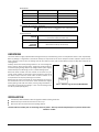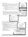
1
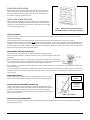
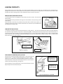
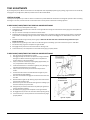
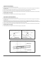
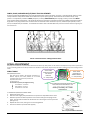
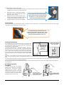
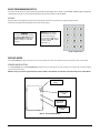
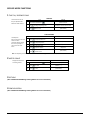
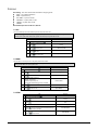
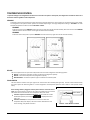
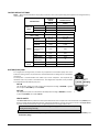
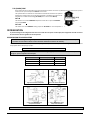
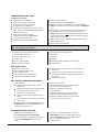
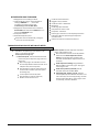
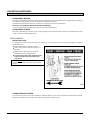
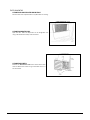
ST/VT SINGLE TEMP/VARIABLE TEMP GLASSFRONT VENDOR MODELS: 3521/3521A – ST 3000 (3 WIDE) 3519/3519A – ST 5000 (5 WIDE) 3520/3520A – VT 3000 (3 WIDE) 3517/3517A – VT 5000 (5 WIDE) SERVICE MANUAL October 2010 ST / VT VENDOR • 3521 3519 3520 3517 • 4218736 Rev A ST / VT VENDOR • 3521 3519 3520 3517 • 2 4218736 REV A TABLE OF CONTENTS INTRODUCTION ............................................................................................................................................................................ 4 SPECIFICATIONS .......................................................................................................................................................................... 4 UNPACKING .................................................................................................................................................................................. 5 INSTALLATION .............................................................................................................................................................................. 5 LOADING PRODUCTS .................................................................................................................................................................. 8 TRAY ADJUSTMENTS ................................................................................................................................................................... 9 SPIRAL ADJUSTEMENT ............................................................................................................................................................. 11 VEND CYCLE - IVEND™ EQUIPPED.......................................................................................................................................... 13 SALES MODE .............................................................................................................................................................................. 13 BASIC PROGRAMMING SETUP ................................................................................................................................................. 14 SERVICE MODE .......................................................................................................................................................................... 14 SERVICE MODE FUNCTIONS .................................................................................................................................................... 15 1 TUBE FILL/ DISPENSE COINS ............................................................................................................................................. 15 2 MOTOR COUNT .................................................................................................................................................................... 15 3 OPTIONS ............................................................................................................................................................................... 15 4 CONFIGURATION ................................................................................................................................................................. 15 5 PRICING ................................................................................................................................................................................ 16 6 ACCOUNTING ....................................................................................................................................................................... 17 7 ADVANCED OPTIONS .......................................................................................................................................................... 17 8 TEST VEND - SINGLE MOTOR ............................................................................................................................................ 17 9 TEST VEND ALL MOTORS ................................................................................................................................................... 17 0 DIAGNOSTICS ...................................................................................................................................................................... 17 TEMPERATURE CONTROL ........................................................................................................................................................ 18 REFRIGERATION ........................................................................................................................................................................ 20 PREVENTIVE MAINTENANCE .................................................................................................................................................... 23 PARTS ORDERING PROCEDURE.............................................................................................................................................. 25 BEFORE CALLING FOR SERVICE ............................................................................................................................................. 25 The Model and Serial numbers are needed for you to obtain quick service and parts information for your vendor. The numbers are given on the identification plates located on the back or inside of the vendor. Write them into the spaces below for your records. MODEL NUMBER: _______________ SERIAL NUMBER: _______________ ST / VT VENDOR • 3521 3519 3520 3517 • 3 If you have questions concerning the information in the manual, replacement parts, or the operation of the vendor, note your machine’s Model and Serial Numbers before contacting: VendNet 165 North 10th Street Waukee, Iowa 50263 - USA Parts: (888) 259-9965 Service: (800) 833-4411 Parts Fax: 515-987-4447 All Other: (888) 836-3638 E-Mail: [email protected] 4218736 Rev A INTRODUCTION This manual contains instructions, service and installation guidelines for the Single Temp (ST) / Variable Temp (VT) Glassfront Vendor. Please read this manual thoroughly and follow the instructions. The initial set-up of a vendor is a very important step of insuring that the equipment operates in a trouble-free manner. The ST Vendor is a single zone temperature vendor. All trays are held to a consistent set temperature. The vending vendor will maintain as low as 2°C (36°F) throughout … maintaining health safety for perishable products. The temperature and health safety settings can be adjusted within the control system (see programming manual). The VT Vendor is a two zone/two temperature vendor. This provides for two temperature zones (top and bottom) in a single vending vendor. The zones are separated by a moveable air deflector and insulating barrier. The vendor has an air duct that runs up and down on the back inner wall of the cabinet. For example: In a 5 tray configured vendor the air deflector and insulating barrier can be moved to provide a refrigerated zone for the bottom two trays while providing a chilled top zone for the top three trays. Positioning of the air deflector and insulating barrier is adjustable in a range of 2 trays in the bottom zone/ 4 trays in the top zone, 3 & 3, or 4 & 2 ... dependent upon product height and tray spacing. The vending vendor will maintain 2°C (36°F) in the bottom zone while the top zone will be as much as high 19°C (66°F) depending upon ambient conditions. The top compartment can be optionally equipped with a heater & blower system along with a separate temp sensor & relay to maintain a constant and/or higher temperature across varying ambient temperatures. Both vendors will operate within an ambient temperature range of 4°C-32°C (40°F-90°F). The temperature setting for both compartments are set within the control system (see programming manual). The bottom or single zone has a temperature sensor. The modular insulated refrigeration system draws air across the refrigeration system’s evaporator coils up the back air duct and circulates down through the trays. There are openings in the bottom trays to allow air to circulate around the products. All programming (pricing, vend functions and features) are also done within the control system. Changes can be made without any additional accessories or remote parts. Selections can be priced individually from $00.00 to $655.35 in five cent increments (US currency). Cash accountability records, total cash transactions, total vend cycles performed by the vendor, information for individual selections, complete rows or total vendor can be compiled and used for inventory and ordering records. Electrical malfunctions are recorded and displayed when the vending vendor is placed in the Service Mode. Non-functional motors or selections are indicated. Each selection has an individual motor. Functional selections will continue to operate if other motors become nonfunctional. The vending sequence is "first-in, first-out" for each selection, permitting stock rotation to maintain fresh products in the vending area. Each ST / VT Glassfront Vendor has the capability of supporting up to two "satellite" vending vendors … such as a direct wired CB300-SAT, or a USD satellite such as a Cold Food (CF-1000) or Frozen Food (FF-2000). The satellite vendor utilizes the host vendor's control system, coin mechanism, bill validator and keypad to perform the vend functions they require. For details on the satellite vendor, refer to the Service Manual pertaining to the specific vendor for installation instructions. Satellite vendors may require optional kits for installation. Access to the service area of this vendor should be permitted only to individuals having knowledge and practical experience in vendor setup and loading, especially in areas of safety and hygiene. SPECIFICATIONS DIMENSIONS & WEIGHTS TYPE MODEL WIDTH ST/VT (3 WIDE) 3520/3521 ST/VT 5000 (5 WIDE) 3520/3521A 3517/3519 29.5 in. (74.9 cm) DEPTH 3517A/3519A 41.2 in. (104.6 cm) 38 in. (96.5 cm) HEIGHT 72 in. (182.9 cm) ESTIMATED WEIGHT1 693 lbs (614 kg) 816 lbs (370 kg) 1 722 lbs (327 kg) 846 lbs (384 kg) EST. SHIPPING WT. Note: 1 Weights will vary depending on tray configuration and optional equipment installed. ELECTRICAL MODEL VOLTAGE CYCLE NOMINAL AMPS Panasonic Super 1/3 Hp 115 VAC 230 VAC Danfoss 1/2 Hp (OPTION) 115 VAC 230 VAC 60 Hz 50 Hz 60 Hz 50 Hz HEATED GLASS 8.0 Amps 4.0 Amps 10.5 Amps 5.2 Amps NON HEATED GLASS 7.0 Amps 3.5 Amps 9.5 Amps 4.8 Amps 110/24 VAC 230/24 VAC 110/24 VAC 230/24 VAC TRANSFORMER ST / VT VENDOR • 3521 3519 3520 3517 • 4 4218736 REV A REFRIGERATION HORSEPOWER TYPE CONTROLS REFRIGERANT Panasonic Super 1/3 Hp Danfoss 1/2 Hp (OPTION) Hermetically Sealed Hermetically Sealed Electronic Electronic R-134a R-134a 20 oz 16 oz CHARGE COIN CHANGER, BILL VALIDATOR, CARD READER TYPE MDB Coin Changer level II or III, Bill Validator Level I, Card Reader Level I or II LOCATION Suitable for indoor use only. This appliance is not suitable for installation in an area where a water jet could be used. SOUND LEVEL PRODUCES LESS THAN 70 DBA DURING NORMAL OPERATION. VENDOR OPERATION RECOMMENDED OPERATING TEMPERATURE Between 40°F and 90°F (4° and 32° Celsius) UNPACKING This vendor was thoroughly inspected before leaving the factory and the delivering carrier has accepted this vendor as their responsibility. Note any damage or irregularities at the time of delivery and report them to the carrier. Request a written inspection report from the claims inspector to file any claim for damage. File the claim with the carrier (not the manufacturer) within 15 days after receipt of the vending vendor. Carefully remove the outside packing material so as not to damage the finish or exterior of the vending vendor. Inspect the vending vendor for concealed shipping damage. Report any damage hidden by the shipping material directly to the delivering carrier on a hidden damage report. Record the model number and serial number of the vendor for your records. These numbers can be found on the serial plates on the rear of the cabinet and/or inside the vendor. Refer to these numbers on all correspondence and inquiries pertaining to this vendor. Remove leg Remove the leg covers by removing the screws fastening the covers to covers (4) the skid boards at all four corners of the vendor. Remove the shipping skids by placing a 2x6 under the vendor, inserting a large screwdriver or FIG 1. : Remove Leg Covers and Skid Boards prying tool into the grove and splitting it in two. Turn the leveling screws in as far as possible. (See Figure 1). INSTALLATION Consult local, state and federal codes and regulations before installing the vendor. Retrieve the keys to the vendor from the coin return cup. Open outer door and remove all internal packing material. Position and level vendor prior to connecting vendor to power. All set up must be completed prior to prevent harm to the installer or vendor. ST / VT VENDOR • 3521 3519 3520 3517 • 5 4218736 Rev A REMOVING THE DOOR The vendor will fit through most doorways (34"+) by opening the vendor outer door and carefully walking the vendor door or cabinet thorough first and then moving the remaining portion of the vendor through. The vendor outer door may be temporarily removed to permit easier movement through a narrower door openings or hallways. To remove the outer door: 1. Disconnect door harnesses: Loosen the nut and bolt attaching the harness retaining spring to the door harness and unhook the spring from the harness. Unplug the door harness and glass heater harness (option) from the power panel. (See Figure 2). Remove harness clamps and cable ties retaining door harness to door. Remove control system cover (see Figure 3) and disconnect door harness plugs from control board. 2. Remove the door: This requires a minimum of two people. Open the door at least 90 degrees. While someone holds the door in place to prevent bending or damage to the bottom pivot, remove the three (3) 5/32" hex socket/Allen screws fastening the top hinge assembly to the top of the door (see Figure 4). Once these screws are removed the door needs to be lifted vertically off the bottom hinge. The bottom hinge pin rests on top of nylon washers to provide proper door height and smooth operation … retain these washers for reassembly. Disconnect door harness plugs FIG 2. : Disconnect harness plugs Remove screw to lift cover FIG 3. : Remove Control Board Cover FIG 4. : Remove Top Door Screws REMOVING THE HINGES AND FRONT LEG MOUNTS The cabinet depth can be narrowed to approximately 31" with the additional removal of the door hinges and front leg mounts. These may be temporarily removed to permit easier movement through a very narrow door openings (32") or narrow/angled hallways. 1. Mark the Door Hinge locations: Mark the location of the top and bottom hinges with a pencil for proper locating upon reassembly. 2. Remove the Top Hinge: Remove the two (2) small locating screws and four (4) large bolts and nuts holding the Top Hinge Plate to the cabinet (See Figure 5). Save the mounting hardware for reassembly. 3. Remove the Front Leg Mounts: From the underside of the cabinet remove the four (4) bolts that secure the front leg mounts. NOTE: Be sure to leave the two inside bolts on each cabinet leg. Pull the leg mounts out forward to remove. (See Figure 6.) 4. Move machine in to final location 5. Reassemble in reverse order 6. Level vendor and check door handle closure FIG 5. : Remove Top Hinge Remove these 4 bolts Leave these 2 bolts FIG 6. : Remove Leg Mounts ST / VT VENDOR • 3521 3519 3520 3517 • 6 4218736 REV A POWER CORD INSTALLATION Remove the power cord from inside the vendor. Remove the connection box cover retaining screw and route the cord under the cover. Keep power cord secured on the center back of the cabinet until the vendor is placed into its final location to prevent damage to the cord. INSTALL BACK SCREEN PROTECTOR Remove the screws holding the top screws from the screen on the back of the vendor. Hook the small flange of the Back Screen Protector under the bottom of the screen. Fasten the Back Screen Protector in place with the screen screws removed previously (See Figure 7). FIG 7 . : Back Screen Protector Installation (hook from bottom, screws at top, airflow up) LEVEL THE VENDOR Position the vendor in its place of operation no farther than nine feet from the power outlet or receptacle. Check that the door will open fully without interference. Leave at least four (4”) inches of space between the back of the vendor and any wall or obstruction for proper air circulation. All levelers must touch the floor. The vendor must be level for proper operation, cabinet to door alignment, condensate drainage and for acceptance of coins through the coin mechanism. Adjust the four (4) leg levelers on the cabinet legs first to make the cabinet level frontto-back and left-to-right. After the cabinet is level adjust the front leg mount levelers to touch the floor surface. The front leg mount levelers should not support for the weight of the cabinet. GROUNDING (EARTHING) & ELECTRICAL Consult local, state, and federal codes and regulations before installing the vendor. Refer to the Safety Installation Guidelines document found in the service package shipped with your vendor. Before connecting the vendor, the integrity of the main electrical supply must be checked for correct polarity, presence of ground (earth) and correct voltage. These checks should be repeated at six-month intervals with the routine safety electrical testing of the vendor itself. If the receptacle is not properly grounded or polarized, contact a licensed electrician to correctly polarize and/or ground the receptacle to ensure safe operation. For proper operation of any equipment utilizing electronically controlled components, the equipment should be placed on an isolated, or dedicated, noise-free circuit properly polarized and grounded. Use of a surge suppressor is recommended for locations where electrical noise is present. MAIN POWER SWITCH Plug the power cord into a dedicated power outlet. Open the vendor door. Turn on the main power switch located on the Power Panel within the cabinet. See Figure 8. DOOR GLASS HEATER HARNESS CONNECTION The Door Glass Heater Harness Connection is normally disconnected to conserve energy. In environments where the humidity is above 70% the Glass Heater Harness should be connected to prevent water condensation from forming on the glass surface. When the ambient conditions are below 70% humidity the glass should be disconnected. See Figure 8. Main Power Switch Door Glass Heater Connection FIG 8. : Power Panel ADVANCED POWER MANAGEMENT The Vendor control system is capable of conserving energy by adjusting time periods and temperature for the refrigeration and lighting. (see programming manual). ST / VT VENDOR • 3521 3519 3520 3517 • 7 4218736 Rev A LOADING PRODUCTS Load products from front to back making sure all items fit freely between the spiral spaces. Do not attempt to force oversize items or packages into the spaces. Do not skip a space. Place the product on the bottom of the compartment on the product spirals with the label facing the front of the vending vendor for easy identification by the customer. See Figure 9. SNACK/CANDY/FOOD TRAY OPTION To load products, lift the tray slightly and pull forward until the tray stops. The trays tilt for easier loading. The size of the item being vended must be larger than the diameter of the spiral being used to vend properly. Undersized items could cause vend problems. If the product does not fit the spiral properly, use a different pitched spiral. Call the number located within this manual for spirals available from your distributor or service entity. Figure 9. Loading Products CAN/BOTTLE TRAY OPTION To unlatch the Can/Bottle Trays place both hands with your under palms up … then push out simultaneously with your thumbs depressing the slide left and right side latches and pullout as shown (See Fig ###?) . Carefully load products vertically as shown. Some bottle and/or can containers present and vend better by using the provided spiral risers. If the product requires additional vertical space or presents/vends poorly remove the risers as necessary. Some bottle beverages may require an optional kit for proper vending – call the number located within this manual for further information.. Pull out on tray to load Push out on latches with thumbs Spiral Risers Figure 10. Tray Latches HIGH CAPACITY CAN TRAY (HCCT) OPTION Some vendors come equipped with the HCCT option. There is two setups for the HCCT option … one for the vending 355ml (12oz.) and one for 375ml (13oz.) cans. The HCCT option is only provided for these two can sizes with identical diameters. Load product horizontally from front to rear and stack a maximum of three (3) levels high. See Figure 11. Install a display can in the provided areas in front of each selection as shown. Adjust the price scrolls to the desired price. Load cans horizontally up to 3 high as shown Load display cans as shown in front of each selection Figure 11. High Capacity Can Tray OPTION ST / VT VENDOR • 3521 3519 3520 3517 • 8 4218736 REV A TRAY ADJUSTMENTS By re-timing the spirals, difficult-to-vend items can be dispensed more dependably. By altering tray spacing, larger items can be vended. By changing the tray configuration, different product mixes can be accommodated. VERTICAL SPACING The trays can be adjusted up or down in half-inch increments to provide additional headroom for vending taller products. When increasing the height in one area, the same amount of room will be lost in the tray above or below the one being adjusted. 3 WIDE SNACK/CANDY/FOOD TRAY REMOVAL AND REPOSITIONING 1. 2. 3. 4. 5. 6. 7. 8. 9. Pull out the tray to be adjusted until it stops. Disengage the tray harness from its retainer on the right side wall. See Figure 12. Disconnect the tray plug from its receptacle on the right side wall. Lift up on the rear of the tray and remove it from the vendor. Disengage left and right tray rails from their corresponding slots on the left and right side walls by pulling inward on the bottom front of each rail and lifting its flange out of the slot. Pull each rail forward to disengage its rear tabs from the hole in the rear wall. Relocate both left and right rails by reversing step 4. Rails must be level from front to back and evenly spaced from top to bottom of each side. Replace the tray by placing its rear rollers on the left and right rails and lifting up on the front of the tray as it is rolled back. Re-install the tray plug into its receptacle on right side wall. Re-engage the tray harness into its harness retainer. See Figure 12. Test-vend the tray in its new position to assure that the tray plug is properly seated. 5 WIDE SNACK/CANDY/FOOD TRAY REMOVAL AND REPOSITIONING 1. 2. 3. 4. 5. 6. 7. 8. 9. 10. 11. 12. 13. Pull out the tray to be adjusted until it stops. Disengage the tray harness from its retainer on the right side wall. See Figure 12. Disconnect the tray plug from its receptacle the harness retainer on the right sidewall. Lift up on the front of the tray and pull slightly (approximately 1.5 cm /.5 in) forward to clear the tray stop. Locate the release lever on the left and right tray rails. (See Figure 13) Swing the release levers up to unlatch. Lift up on the rear of the tray and remove the tray from the vendor. Unscrew the two screws to remove both left and right tray rails from the left and right sidewalls. Pull each rail forward to disengage its rear tab from the hole in the rear wall. Relocate left and right rails by reversing step 6. Rails must be level front to back and left to right. Place the tray rear rollers on the left and right rails and lifting up on the front of the tray and push it back. Swing the tray rail release levers all the way down (this guides the tray for tilting when loading). Re-install the tray plug into its receptacle on the right side wall. Re-engage the tray harness into its harness retainer (See Figure 12) Test-vend the tray in its new position to assure that the tray plug is properly seated. Figure 12. Tray Harness Connection Figure 13. Tray Rails ST / VT VENDOR • 3521 3519 3520 3517 • 9 4218736 Rev A CAN/BOTTLE TRAY REMOVAL 1. Unlatch the tray and pull it all the way out until it stops. 2. Disengage the tray harness from its harness retainer on the right side wall. See Figure 12. Disconnect the tray plug from its receptacle on the right side wall. 3. Remove and save the six (6) screws that fasten the tray to the left and right slides. Lift up and forward to remove the tray. 4. Pull out on slides and remove and retain the screws fastening the slides to the side walls (See Figure 15). 5. Relocate the slides and re-install with screws through the slides into the side walls. Assure slides are mounted level and in same location from left to right and front to back. 6. Reverse procedure to re-install tray. 7. Test-vend the tray in its new position to assure that the tray plug is properly seated. HIGH CAPACITY CAN TRAY REMOVAL 1. 2. 3. 4. 5. 6. 7. Unlatch the tray and pull it all the way out until it stops. Disengage the tray harness from its harness retainer on the right side wall. See Figure 12. Disconnect the tray plug from its receptacle on the right side wall. Remove and save the four (4) nuts located near the corners of underneath the tray. (See Figure Figures 14a&b). Lift up and forward to remove the tray. Remove and save the six (6) screws that fasten the tray to the left and right slides. Lift up and forward to remove the tray. Pull out on slides and remove and retain the screws fastening the slides to the side walls. Relocate the slides and re-install with screws through the slides into the side walls. Assure slides are mounted level and in same location from left to right and front to back. Reverse procedure to re-install tray. Test-vend the tray in its new position to assure that the tray plug is properly seated. 1. 3. 2. Figure 14a. Tray Mounting Nut - Left Front 4. Figure 14b. Tray Mounting Nut - Left Rear Figure 15. Drawer Slide Removal (Left Shown) ST / VT VENDOR • 3521 3519 3520 3517 • 10 4218736 REV A CANDY, SNACK, AND MEDIUM (3/4) SNACK TRAY ADJUSTMENTS All of the Snack/Candy/Food/Beverage Trays have adjustable divider locations. By adding, removing, or relocating divider positions a wide variety of selection compartment widths can be obtained as required. (See Figure 16). The dividers can be located in every ½ Candy position. This adjustment provides for CANDY (candy bars, crackers), MEDIUM SNACK (small chip bags, cookies), and full sized SNACK (chips, pastries) width compartments. The divider adjustments also provide for compartments wider than a SNACK compartment width for larger items. Every tray provides motor connections for the maximum number of selections per tray. Additional parts (dividers, motors, spirals, and adapter kits) are available … For additional information refer to the Parts & Service portion of the website listed at the beginning and Full sized SNACK Width 5-3/4" MEDIUM SNACK Width 4-5/16" CANDY Width 2-7/8" end of this manual. FIG 16.: Divider Positions and Approximate Sizes SPIRAL ADJUSTEMENT The shape, size and thickness of a product affect how well it falls off the tray. Most products can be vended successfully when the spiral end is positioned at 6 o’clock. If vending problems occur with spiral ends at the standard 6 o’clock position, adjust the drop-off either by retiming the spiral or installing a Product Pusher. ADJUST SPIRAL COUNTER CLOCKWISE FOR THICKER PRODUCTS (i.e. 3:00 (0'CLOCK)) SPIRAL TIMING SNACK/CANDY/FOOD TRAY Each spiral can be rotated in 20º (degree) increments for a different drop-off point. Most products can be vended successfully when the spiral end is positioned at the position of 6 o’clock. The general rule is: The narrower the product, the higher the timing. Thick Products - 4-6 o’clock Most products – 6 o’clock Thin Products - 6-8 o’clock ADJUST SPIRAL CLOCKWISE FOR THINNER PRODUCTS (i.e. 7:00 (0'CLOCK)) ADJUST SPIRAL END POSITION FOR SUCCESFUL VEND. MOST PRODUCTS VEND PROPERLY AT THE 6:00 (0'CLOCK) SETTING SHOWN ABOVE TO CHANGE SNACK/CANDY/FOOD SPIRAL TIMING: 1. 2. 3. 4. 5. Remove the motor cover. Raise the motor slightly and pull forward on the spiral until it separates from the motor. Rotate the spiral to the desired position and re-insert the hub (spiral coupling) into the motor. The hub must be seated over the vertical rail or retaining rib on the tray as shown (See Figure 17). Replace the motor cover, making sure it is securely tightened. Test-vend to make sure product vends properly. FIG 17.: Spiral and Motor Connection ST / VT VENDOR • 3521 3519 3520 3517 • 11 4218736 Rev A TO CHANGE CAN/BOTTLE/HCCT SPIRAL TIMING: Each spiral can be rotated in 45º (degree) increments for a different drop-off point. Most products can be vended successfully when the spiral end is positioned at 6 o’clock. 1. 2. 3. Reach behind motor to release spiral coupling from motor. Pinch spiral coupling ends and pull forward on spiral to remove. Rotate the spiral to the desired position and reinsert the spiral coupling into the motor. The spiral coupling must be fully seated into the motor. Test-vend to make sure product vends properly. ADJUST SPIRAL END POSITION BY PINCHING SNAP TABS OF SPIRAL COUPLING ON BACK OF MOTOR - PULL OUT OF MOTOR THEN SNAP BACK INTO DESIRED POSITION Product Pushers If the product still will not vend properly after re-timing of the spiral then install a Product Pusher. The Product Pushers are provided in the service package of the vendor. Snap onto spirals only as necessary as shown. IF AFTER ADJUSTING THE SPIRAL END THE PRODUCT STILL DOESN'T FALL OFF TRAY … SNAP PROVIDED PRODUCT PUSHERS ONTO END OF SPIRALS TO ENSURE PRODUCT WILL FALL Loading Coin Mechanism INSERT COINS THROUGH The Coin Mechanism must be loaded with some level of each coin in order FRONT DOOR COIN INSERT TO FILL COIN TUBES for the vendor to operate properly. The coins need to be loaded into the PRESS SERVICE coin mechanism by insertion into the front coin insert. First enter the MODE BUTTON SERVICE MODE then TUBE FILL MODE AND ENTER (See SERVICE MODE instructions – COIN/TUBE FILL MODE). Make sure to TUBE FILL load the correct coins into their correct tubes. Each tube should be kept MODE (PRESS 1) loaded with at least one roll of each coin to keep above the tube low level sensors. Once the tubes are loaded to these levels the Dollar Bill Validator will accept bills. If the coin tubes fall below this level the Dollar Bill Validator may stop accepting bills and the front display will indicate "EXACT CHANGE ONLY". Alternatively, you can load the coins into the slots above the respective coin tubes. This is not the preferred method. By using TUBE FILL mode the control board can then accurately determine coin levels. On some Coin Mechanisms there are buttons above each tube to dispense the coins (may vary depending on which coin mechanism that is used). The coins can also be dispensed within the Service Mode described later. More advanced and brand specific Coin Mechanism operating instructions can be obtained in the Service portion of the website listed at the beginning and end of this manual Bill Validator Operation (OPTIONAL) To remove the bills from the Dollar Bill Validator push the tab on the top of the bill box and lift up. To clear jams or cleaning unlatch lower unit as shown. Dollar Bill Validator cleaning instructions as well as more advanced service information can be obtained on the Service portion of the website listed at the beginning and end of this manual. ST / VT VENDOR • 3521 3519 3520 3517 • 12 4218736 REV A VEND CYCLE - IVEND™ EQUIPPED All vendor selections have been assigned at the factory to be monitored for iVend™ optical sensing. For 5 milliseconds at the start of a vend, the iVend™ optical sensor will be checked to make sure it is not blocked, damaged or disconnected. If blocked, damaged or disconnected - the normal home-switch-vend cycle will be used and the optical sensors will be ignored. Both the vend motor and a vend timeout timer are started. The selection motor rotates to the home-switch position. If there is a home-switch signal, then the vend is considered successful. If after 10 seconds there is no home-switch signal, the vend failed. The vend motor is shut down and MAKE ALTERNATE SELECTION is displayed. The customer can press selection buttons to activate another motor or press the coin return button. If not blocked, damaged or disconnected - the iVend™ Sensor System is used. The vend motor and a vend timeout timer are started. The selection motor rotates to the home-switch position. If a product is detected during this time period, then the vend is considered successful. If after reaching the home-switch position and a product is not detected, then the vend motor will pause for 1 second while the controller continues to monitor the optical sensor for product delivery. o If a product is detected during this pause, then the vend is considered successful. o If a product is not detected, then the controller initiates a second vend cycle and another vend timeout timer while continuing to monitor the optical sensor. If a product is detected during this second cycle, the motor will be stopped immediately. The vend is considered successful. The 2ND VEND accounting counter is increased by one. If after reaching the home-switch position and a product is not detected, then the vend motor is stopped and for 2 seconds the controller continues to monitor the optical sensor for product delivery. If a product is detected, the vend is considered successful. The 2ND VEND accounting counter is increased by one. Otherwise, if no product is detected, the selection is sold out. Such a state will trigger the display of the MAKE ALTERNATE SELECTION message. The amount of credit is displayed. The customer can press selection buttons to activate this or another motor or press the coin return button. o If after 10 seconds there is no home-switch signal and no product is detected, then the vend failed. The vend motor is shut down and MAKE ALTERNATE SELECTION is displayed. The customer can press selection buttons to activate another motor or press the coin return button. NOTE: Force Vend is disabled to permit customer to retrieve deposited money. SALES MODE The vendor automatically defaults to Sales Mode after it is turned on. In the Sales Mode, the vendor accepts money deposits, pays out change and dispenses product to the customer. DISPLAY CREDIT - ELECTRONIC PRICING This vendor is equipped with the Electronic Pricing feature. The customer may verify the price by pressing the selection number (i.e. 22) before inserting money. If a selection is made and credit has not been established, the price for that selection is displayed and “INSERT MORE MONEY” will be displayed. When money or credit is accepted, then the amount of credit is displayed. "USE EXACT CHANGE ONLY" MESSAGE OPERATION If the coin levels in the coin mechanism tubes are below the low-level sensors, “USE EXACT CHANGE ONLY” will be displayed. This indicates the Coin Mechanism does not have enough coins in the coin mech tubes to make change. This also indicates that the Dollar Bill Validator may be disabled until change can be made. ST / VT VENDOR • 3521 3519 3520 3517 • 13 4218736 Rev A BASIC PROGRAMMING SETUP This portion of the manual includes only basic Service Mode Programming functions. Refer to the CONTROL SYSTEM Programming Manual included with the vendor for more advanced description of all functions within the Service Mode. KEYPAD Use the buttons on the keypad as directed in the step-by-step instructions in this manual in programming the vendor. Entries from the keypad will be displayed on the front vendor display. DISPLAY Check the display after pressing the Service Mode Button and/or Keypad Buttons to make sure that the program is responding correctly. Buttons 0-9 are used to move between the various modes, menus and submenus; while the button is used to enter a menu, confirm or save a setting. See Figure 18 FIG 18.: Keypad Layout SERVICE MODE Use the Service Mode to program and service the vendor. Use the keypad as an input device. Watch the display for information while in Service Mode. SERVICE MODE BUTTON To enter Service Mode, press the Service Mode Button located on the top or upper right corner of the controller cover (See Figure 19) To exit Service Mode, press the Service Mode Button. NOTE: If no key is pressed for approximately one minute while in Service Mode, the controller will automatically return to Sales Mode. Service Mode Button Board Power LED OPTIONAL DEX Jack MDB Status LED's FIG 19. : Service Mode Button ST / VT VENDOR • 3521 3519 3520 3517 • 14 4218736 REV A SERVICE MODE FUNCTIONS 1 TUBE FILL/ DISPENSE COINS TUBE FILL Tube Fill counts coins as they are deposited and Shows the dollar amount. STEP 1. 2. 3. DISPLAY Motor Count 60 Press Service Mode Button Press and begin depositing coins Press 2 times to exit At least 15 of each denomination (Sales Mode) TUBE DISPENSE Tube Dispense Pays out coins from the coin mech coin tubes. This mode will also display the current quantity of coins in the coin mech tubes. STEP 1. 2. 3. 4. 5. DISPLAY Press to dispense dollar coin Press to dispense quarters Press to dispense dimes Press to dispense nickels Press 2 times to exit $1.00/coins 0.25/coins 0.10/coins 0.05/coins (Sales Mode) Note: For dispensing more than a 4 denomination coin mech use keys greater in the same sequence as shown above. 2 MOTOR COUNT Displays the total count of working motors. STEP 1. 2. 3. DISPLAY Press Service Mode Button Press then wait. Press to exit. Motors ( - - ) Motors ( - - ) (Sales Mode) 3 OPTIONS (See CONTROL SYSTEM Programming Manual for more information) 4 CONFIGURATION (See CONTROL SYSTEM Programming Manual for more information) ST / VT VENDOR • 3521 3519 3520 3517 • 15 4218736 Rev A 5 PRICING Price Setting - This menu allows these methods for assigning prices: ITEM — by individual selections ROW— by shelf or tray ALL ITEMS — by entire vendor. COUPONS — by Item, Row, or ALL TOKENS — by Item, Row, or ALL COMBO The maximum price that can be set is $655.35. 5.1 ALL This menu allows you to set the selection price of every item all at once. Time Saving Suggestion: Instead of setting the price of each item one at a time, it is much faster to set the common price of the entire vendor; then go back and set the price of each item or row. STEP 1. 2. 3. 4. 5. DISPLAY Motors ( - - ) Press Service Mode Button Pricing Press Press to enter price Press to save. Press ALL Items $0.50 ALL Items $0.50 (Sales Mode) 3 times to exit. 5.2 ROW Use this menu to set the price of a row (shelf) all at the same time. Time Saving Suggestion: Instead of setting the price of one item at a time, set the common price of a Row, then go back and set the price of each item. STEP 1. 2. 3. 4. 5. 6. DISPLAY Motors ( - - ) Press Service Mode Button Pricing Press Press Enter row number and price Example: Top row=01, row below top row=02, etc. Program will automatically go to the next Row. Press to save. Press 3 times to exit Row: - - $0.00 Row:01 $0.50 Row 01 $0.50 (Sales Mode) 5.3 ITEM STEP 1. 2. 3. DISPLAY Motors ( - - ) Press Service Mode Button Pricing Press Item Press 4. Enter Item and price Item 010 $0.50 5. Press to save. The program will automatically go to the next selection number. Item 010 $0.50 6. Press (Sales Mode) 3 times to exit. ST / VT VENDOR • 3521 3519 3520 3517 • 16 4218736 REV A 5.4, COUPON, TOKEN, COMBO (See CONTROL SYSTEM Programming Manual for more information) 6 ACCOUNTING Use this menu to gain access to menus that display or reset data the various types of cash and vend totals. Counts can be viewed by individual items, rows or as the whole vendor. (See CONTROL SYSTEM Programming Manual for more information) 7 ADVANCED OPTIONS (See CONTROL SYSTEM Programming Manual for more information) 8 TEST VEND - SINGLE MOTOR Use this menu to test-vend individual motors. The selection will display with the test-vend. If a test-vend attempt on a particular motor fails, the controller will beep. STEP DISPLAY 1. Press Service Mode Button 2. Press Item - - - 3. Press selection number on keypad and wait Item 010 4. Repeat step 3 for other selections. 5. Press Motors ( - - ) (Sales Mode) 3 times to exit. 9 TEST VEND ALL MOTORS Use this menu to test-vend all motors. The selection will display with the test-vend. If a test-vend attempt on a particular motor fails, the controller will beep. Satellite vendors will also be included in the test. NOTE: Pressing at any time will stop the test STEP 1. 2. DISPLAY Motors ( - - ) Press Service Mode Button Press Item and wait. The motor selection number will display while it is being tested. 3. Press Item 010 (Sales Mode) 3 times to exit. 0 DIAGNOSTICS (See CONTROL SYSTEM Programming Manual for more information) ST / VT VENDOR • 3521 3519 3520 3517 • 17 4218736 Rev A TEMPERATURE CONTROL To prevent damage to the refrigeration unit when it is turned off or the power is interrupted, the refrigeration unit will not restart for at least three minutes regardless of the temperature. SENSORS Temperature sensor(s) are positioned to best represent the product temperature. The sensor(s) are monitored by the control system. The refrigeration and optional heater systems are activated depending on the target temperature setting or SET POINT. The total allowable temperature variation from the SET POINT is DELTA. SENSOR1 Single Zone versions have SENSOR1 located near the top-right of the vendor cabinet assembly. Dual Zone versions have SENSOR1 located under the dual zone barrier on the right side of the cabinet assembly. SENSOR2 Dual Zone versions may have an optional SENSOR2 mounted near the top-right of the vendor cabinet assembly. RELAYS The control system controls up to three relays which then control the refrigeration and heating systems: RELAY1— Controls the compressor and the condenser fan (refrigeration system). RELAY2— Controls the evaporator fan (refrigeration system). RELAY3 OPTION— Controls the optional upper zone blower and heater system. DOOR SWITCH The door switch is located in the upper right corner of the vendor door assembly (See Figure 20). The door switch is monitored by the control system for evaluating when to run the refrigeration and evaporator systems as well as when to reset optional health safety. If the vending vendor is plugged in and the power switch is on and the door is open, then the compressor, evaporator fan, heater and heater fan are all turned off. A 30 minute door timer starts and a compressor delay timer starts. If the door is open for more than 30 minutes, the controller will resume closed door operation, the message DOOR ALERT is displayed and error code is set. If the door is closed, then evaporator fan is turned on. When the compressor delay timer expires, then the controller evaluates the zone sensor readings, relay states and timers. ST / VT VENDOR • 3521 3519 3520 3517 • 18 Door Switch FIG 20 . : Door Switch Location 4218736 REV A FACTORY DEFAULT SETTINGS NOTE: Please read and follow the step-by-step instructions in the Control System Programming Manual to change the factory default settings. PROGRAM VERSION PROGRAM VERSION ENGLISH SPANISH °F (Fahrenheit) °C (Celsius) COLD COLD OFF OFF All selections set to .75 All selections set to 50.00 36°F (2C) 39°F (4 C) 7°F 7°F (4 C) 15 MIN 15 MIN DEFROST PERIOD (Comp Continuous Run Time) 2 HRS 2 HRS DEFROST DELAY (timer) 8 HRS 8 HRS HEALTH SAFETY COLD COLD RANGE (health/safety) All All SET POINT 63°F 63°F (16 C) DELTA 5°F 5°F (3 C) PROGRAM MODE TEMPERTURE DEGREE MODE PRICE • ITEM(S) SET POINT DELTA DEFROST DURATION SENSOR1 SENSOR2 OPTION BOTTOM (COOL) ZONE For a Single Zone vending vendor, the entire tray compartment is the Bottom (Cool) Zone. For a Dual Zone vending vendor, the product trays contained below the insulating barrier is the Bottom (Cool) Zone. The evaporator is located between the lowest tray and the compressor. The evaporator fan distributes cold air to products in the bottom zone. The refrigeration compressor is fully insulated and is located below the bottom (cool) zone. CUT-IN The refrigeration system is turned on when the temperature reading of SENSOR1 is greater than or equal to SET POINT plus half of DELTA. CUT-OUT The refrigeration system is turned off when the temperature reading of SENSOR1 is less than or equal to SET POINT minus half of DELTA. HEALTH SAFETY The HEALTH SAFETY feature prevents the sale of perishable food if the air temperature inside the bottom zone (SENSOR1) rises above the health safety temperature limits for cold food products (41°F / 5°C) for more than 15 minutes. The SZF/DZF Vendor can vend cold food products that require storage temperatures in the range of 32°F to 41°F. NOTE: The time requirements for the COLD setting do not apply for 30 minutes immediately following vending vendor filling or servicing. IMPORTANT! The operator is responsible for enabling the health safety for vended product. Refer to the CONTROL SYSTEM Programming Manual for additional instructions on how to set the Health Safety and Health Safety Range. ST / VT VENDOR • 3521 3519 3520 3517 • 19 4218736 Rev A TOP (WARM) ZONE If the vending vendor is a Dual Zone, then the trays above the barrier are in the Top (Warm) Zone. If the optional heater system is installed, then an optional temperature SENSOR2 is also installed. The optional heater is inside the air duct located on the back of the cabinet. An optional blower fan is located on the top corner above the heater. The blower is turned on if the temperature is outside of the setting (SET POINT plus or minus half of DELTA). CUT-IN The heater turns on when SENSOR2 temperature is less than or equal to SET POINT minus half of DELTA. CUT-OUT The heater turns off if SENSOR2 reading equals the SET POINT or if the compressor is on. REFRIGERATION To prevent damage to the refrigeration unit when it is turned off or the power is interrupted, the refrigeration unit will not restart for at least three minutes regardless of the temperature. REFRIGERATION TROUBLESHOOTING CAUTION: Breaking the refrigerant joints or seals on the system voids the unit warranty. Failure to keep the condenser coil clean and free of dirt and dust and other similar debris voids the unit warranty. Know and understand how the unit operates. Units may vary, but the operation is basically the same. Never guess at the problem; find the symptom before attempting any repair. NOTE: MOST REFRIGERATION PROBLEMS ARE ELECTRICAL. WARNING: Wiring diagrams must be followed as shown. Wrong wiring may cause serious electrical hazard and potential damage or rupture component electrical parts. TABLE 1. APPROXIMATE WINDING RESISTANCE Across Terminals Panasonic Super 1/3 Hp Danfoss 1/2 Hp COMMON to START: 7.53 Ohms 2.9 Ohms COMMON to RUN: 1.06 Ohms 0.7 Ohms COMMON to SHELL: No continuity No continuity Figure 21a. Panasonic Compressor Figure 21b. Danfoss Compressor Figure 21c. Panasonic 1/3 Hp Compressor Schematic Figure 21d. Danfoss 1/2 Hp Compressor Schematic NOTE: The sealed hermetic system should not be worked on outside the Factory Service Center . ST / VT VENDOR • 3521 3519 3520 3517 • 20 4218736 REV A COMPRESSOR WILL NOT START Compressor has no power: Vending vendor not plugged in. Tripped circuit breaker or blown fuse. Faulty wall outlet or improper wiring. Faulty (short or open) power cord. Low voltage. Check the power source with a volt meter. Minimum 103V for 115VAC, 60Hz. Minimum 195V for 230VAC, 50 Hz. Check motor protector (overload). Troubleshooting Circuits with Multi-Meter. Check compressor starting relay. Troubleshooting Circuits with Multi-Meter. Check compressor winding. Troubleshooting Circuits with Multi-Meter. Defective refrigeration relay. Switch the controller to Service Mode then verify that the relay turns on by using the TEST RELAY menu. Unplug power to the vending vendor. Open the power panel. Use insulated jumper wires to short the wire terminals on RELAY1; between 2 and 4 and between 6 and 8. Restore power to the vending vendor. The compressor should start, indicating a problem in the control circuit. Check relay terminals 1 to 0 with a Multi-Meter. Should have 24VDC applied to them. Check the door switch operation. CAUTION: Replace air filter every 3 months to maintain proper air circulation to the condenser and to prevent dirt and debris from clogging up the condenser. NOISY OR VIBRATING UNIT 1. Components rubbing or touching each other. Check fan blades and motor. Loose shrouds and harness. Copper tubing. Loose or unsecured parts. Dirty condenser fan blades. 2. Worn or aged compressor grommets. 3. Compressor. Bad valves. Slugging. Bad windings (Refer to TABLE 1 and schematic). Voltage too low. UNIT SHORT CYCLES Defective condenser fan. Dirty or blocked condenser coils. Dirty or blocked air filter. Dirty or blocked inlet or outlet screens. Defective overload (motor protector). Temperature sensor is defective or not mounted in the correct spot. Temperature setting set too warm. See Temperature Control section and Factory Default Settings section of this manual. Defective control board. UNIT OPERATES LONG OR CONTINUOUSLY 1. Airflow restricted. Clogged or blocked inlet screen, air filter, or outlet screen. Exhaust area blocked. Vendor too close to wall. Airflow blocked by product in front of evaporator or air duct openings. Coils icing due to faulty evaporator motor or blades. Loose connections on evaporator motor. Motor not running. 2. Refrigeration relay shorted. Switch the controller to Service Mode, then use the TEST RELAY menu to verify that the relay turns off. 3. Gasket leak around door. 4. Excessive load: After loading, unit runs longer to pull out excessive heat from product. 5. Shortage of refrigerant or restriction. 6. Faulty controller. 7. Ambient air temperature and relative humidity exceed manufacturer’s operational standards. 8. Defective temperature sensor or sensor has been moved or remounted to wrong spot. REFRIGERATED SPACE TOO COLD 1. Refrigeration control setting too cold. 2. See Troubleshooting Circuits with Multi-Meter. 3. Troubleshooting Circuits with Multi-MeterCheck the program DIAGNOSTICS and look for error codes. ST / VT VENDOR • 3521 3519 3520 3517 • 4. Refrigeration relay bad. Switch the controller to Service Mode, and then verify that relay turns on by using the TEST RELAY menu. Check relay terminals for continuity with an ohmmeter. 5. Faulty controller. 21 4218736 Rev A REFRIGERATED SPACE TOO WARM 1. Refrigeration control setting too warm. 2. Check temperature sensor. If the temperature reading of SENSOR1 is “- - -“, then check connections and sensor harness. See Condenser airflow restricted. Plugged or dirty condenser. Condenser motor or blades bad. Blade stuck. Condensing space restricted. Unit placed too close to a wall. Compressor - bad valves. Low charge or restriction in tube if capillary tube starts frosting 8 to 20-25 cm (10 inches) past evaporator connection tube. Check for oil leaks around brazed connections. Troubleshooting Circuits with Multi-Meter 3. Refrigeration relay bad. Switch the controller to Service Mode and verify that the RELAY1 turns on by using the TEST RELAY menu. 4. Faulty control board. 5. Restricted evaporator space. Evaporator motor or blades faulty, causing the coils to ice over the evaporator. TROUBLESHOOTING CIRCUITS WITH MULTI-METER Caution: Power must be disconnected and fan circuit open. B. Danfoss 1/2 HP – Remove relay from compressor. To check the power source, use the voltage section of the Multi-Meter. Acceptable range is 103-127VAC for 115V (60Hz), or 195-255VAC 230V (50Hz). Check compressor starting relay. A. Panasonic.1/3 HP - Unscrew lead terminals and (Figure 21b and Figure 21d). Use ohmmeter to check for continuity between switch terminals Check temperature sensor harness to control board for continuity using ohmmeter of Multi-Meter. Replace if there is no continuity. Check compressor windings using ohmmeter. Refer to TABLE 1, Figure 21a, Figure 21b, Figure 21c and Figure 21d.. Check motor protector (overload). Use the ohmmeter section of the Multi-Meter. Panasonic1/3 HP , Danfoss 1/2 HP – Remove overload (Danfoss) Check between terminals 1 and 3 for continuity. If no continuity (infinity), overload may be tripped. Wait 10 min. and try again. If still no continuity, overload is defective. remove relay from compressor. (Figure 21a and Figure 21c). Keep relay upright. Use ohmmeter to check for continuity between switch terminals 1 and S. Replace relay if continuity exists. Use ohmmeter to check for continuity across coil terminals 2 and M. If open then replace the starting relay. 1 and 2. Replace if continuity exists. Use ohmmeter to check for continuity between coil terminals 5 and 2. ST / VT VENDOR • 3521 3519 3520 3517 • 22 4218736 REV A PREVENTIVE MAINTENANCE CAUTION: Always disconnect power source BEFORE cleaning or servicing. ONCE A MONTH CLEAN CABINET INTERIOR Wash with a mild detergent and water, rinse and dry thoroughly. Odors may be eliminated by including baking soda or ammonia in the cleaning solution. Plastic parts may be cleaned with a quality plastic cleaner. The vend mechanisms must be kept clean. Any build-up can cause the mechanisms to malfunction. DO NOT GET THE CLEANING SOLUTION ON ELECTRICAL COMPONENTS. To insure proper vending keep delivery box area free of dirt and sticky substances. CLEAN CABINET EXTERIOR Wash with a mild detergent and water, rinse and dry thoroughly. Clean occasionally with a quality car wax. Plastic exterior parts may be cleaned with a quality plastic cleaner. EVERY 3 MONTHS REPLACE AIR FILTER The refrigeration air filter is to prevent dust from building up on the condenser coils and allows the refrigeration system to operate efficiently. Pull the filter holder and check the air filter. If filter is dirty, replace it with the same size and type filter. Airflow arrow on filter must point to the left (towards the inside of vending vendor). On those vendors with air filter handle hook filter holder around filter edge and reinstall clip on opposite end. WARNING: Do not replace with a HEPA type filter. This type may not allow the correct amount of air to flow through. CLEAN BOTTOM INLET SCREEN The inlet screen is a long narrow screen located on the bottom right side. It can only be accessed from underneath the cabinet. Remove dust and debris from the inlet screen to allow air to flow to the condenser coils. ST / VT VENDOR • 3521 3519 3520 3517 • 23 4218736 Rev A EVERY 6-MONTHS CLEAN DOOR AND DELIVERY DOOR SEALS Clean the door seals. Inspect them for any deformities or cracking. CLEAN EVAPORATOR COIL Open the door. Clean the evaporator coil of refrigeration unit using a soft bristle brush and/or vacuum cleaner. CLEAN REAR SCREEN Remove the Back Screen Cover from cabinet back. Clean dust and debris from screen using a soft bristle brush or a vacuum cleaner. ST / VT VENDOR • 3521 3519 3520 3517 • 24 4218736 REV A PARTS ORDERING PROCEDURE When ordering parts, include the following: 1. The model and serial numbers of the vending vendor for which the parts are needed. 2. Shipping address. 3. Address where the invoice should be sent. 4. The number of parts required. 5. Always refer to the pertinent parts and/or part manual for the correct part number and description of a specific part. 6. 7. 8. 9. NOTE: When RIGHT or LEFT is used with the name of a part, it means the person is facing the vending vendor with the door closed. Any special shipping instructions. Carrier desired: air or air special, truck, parcel post or rail. Signature and date. Purchase order number, if used. Mail your order to: VendNet™ 165 North 10th Street Waukee, IA 50263 USA All orders are carefully packed and inspected prior to shipment. Damage incurred during shipment should be reported at once and a claim filed with the terminating carrier. If you do not have the right parts manual: contact VendNet™. If you have any questions, check out our Website www.vendnetusa.com or call VendNet . Ask for the Parts Department. We will be happy to assist you. Email: [email protected] BEFORE CALLING FOR SERVICE Please check the following: Does your vending vendor have at least 6-inches of clear air space behind it? If the power is turned on at the fuse box, is the vending vendor the only thing that doesn’t work? Is the vending vendor plugged directly into the outlet? WARNING: Extension cords can cause problems. DO NOT USE EXTENSION CORDS. Is the evaporator coil free of dust and dirt? Is the condenser coil free of dust and dirt? Is the compressor free of dust? A blanket of dust can prevent the compressor from cooling in between workout cycles. Is the circuit breaker at the fuse box reset? Is the evaporator fan working? To check if the fan is running take a small piece of paper in front of the evaporator coil and see if the evaporator fan will draw the paper.. Is the condenser fan running? Fold a sheet of 8 1/2” x 11” paper in half. Place the paper in front of the condenser coil inlet screen located on the bottom right side underneath the cabinet and see if it draws the paper to it.. Is the shelf in front of the evaporator coil clear? (No tools, product, or other air-restricting items). Is the temperature setting set as specified? See CONTROL SYSTEM Programming Manual . NOTE: Setting the temperature colder does not accelerate cooling of product but may cause the product to freeze. ST / VT VENDOR • 3521 3519 3520 3517 • 25 4218736 Rev A NOTES: The contents of this publication are presented for informational purposes only, and while every effort has been made to ensure their accuracy, they are not to be construed as warranties or guarantees, express or implied, regarding the products or services described herein or their use or applicability. We reserve the right to modify or improve the designs or specifications of such products at any time without notice. VendNet™ 165 North 10th Street Waukee, Iowa 50263 United States of America USA & Canada Service (800) 833-4411 Parts (888) 259-9965 Email Web Site International (515) 274-3641 [email protected] www.vendnetusa.com 4214792•C.DOC 26 SZF/DZF VENDOR • 3521 3519 3520 3517 • 4218736 REV A