1
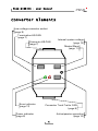
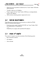
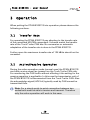
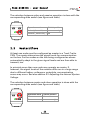
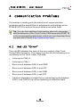
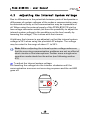
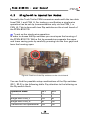
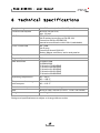
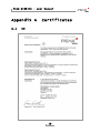
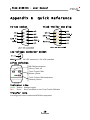
PCAN-B10011S
Converter High-speed CAN to
Truck Trailer CAN
User Manual
PCAN-B10011S - User Manual
Products taken into account
Product Name
Model
PCAN-B10011S
Item Number
IPEH-002041
Last Updates
March 23, 2005
First edition
February 24, 2006
Minor text corrections
Added technical specifications
All product names mentioned herein may be the trademarks or registered
trademarks of their respective companies. Furthermore, "™" and "®" are not
mentioned in each case in this manual.
© 2006 PEAK-System Technik GmbH
PEAK-System Technik GmbH
Otto-Röhm-Straße 69
D-64293 Darmstadt, Germany
Phone: +49 (0)6151-8173-20
Fax: +49 (0)6151-8173-29
www.peak-system.com
[email protected]
2
PCAN-B10011S - User Manual
Contents
1
1.1
1.2
1.3
2
2.1
2.2
2.3
3
3.1
3.2
3.3
4
4.1
4.2
4.3
Introduction
5
Properties at a Glance
System Requirements
Scope of Supply
Installation
5
6
6
7
Connecting the High-speed CAN Side
Connecting the Truck Trailer CAN Side
Power Supply
Operation
7
8
8
10
Transfer Rate
Active/Passive Operation
Master/Slave
Communication Problems
10
10
11
12
Red LED "Error"
Adjusting the Internal System Voltage
Single-Wire Operation Modes
12
13
14
5
Frequently Asked Questions (FAQ)
16
6
Technical Specifications
17
Appendix A
A.1
Certificates
18
CE
Appendix B
18
Quick Reference
3
19
PCAN-B10011S - User Manual
Converter Elements
Low voltage connector socket
(page 8)
Termination HS-CAN
(page 7)
Connector HS-CAN
(page 7)
Error indicator
(page 12)
Internal system voltage
(page 13)
Master/Slave
(page 11)
Connector Truck Trailer CAN
(page 8)
Power indicator
(page 8)
Active/passive operation
(page 10)
4
PCAN-B10011S - User Manual
1
Introduction
Tip: At the end of this manual (Appendix B) you can find a
Quick Reference with brief information about the installation
and operation of the PCAN-B10011S.
The bus converter PCAN-B10011S establishes a connection between
a High-speed CAN node and a Truck Trailer CAN (ISO 11992-1). The
Truck Trailer CAN is, as the name already implies, a communication
link between a truck and its trailer. The bus converter makes this
communication accessible for the commonly used High-speed CAN.
The special conditions of this environment are taken into account,
like long wires, high levels of disturbance, high voltage deviation,
and a small amount of data.
A Truck Trailer CAN consists of at least two nodes. The connection
is done via a two-wire line. The power supply may be done locally
or via the cable from the towcar, where the reference point is the
local bodywork. Bodyworks from the towcar and the trailer are
connected. Due to this configuration there are potential differences
and disturbances the Truck Trailer CAN is optimized for. The
transfer rate is significantly lower than in a High-speed CAN.
The bus converter's design uses the CAN transceiver B10011S from
Atmel. This is the reason for the bus converter's choice of name.
1.1
Properties at a Glance
Direct connection to a HS-CAN component (Sub-D socket, 9
pins)
Switchable termination for HS-CAN
Connection of the Truck Trailer CAN via 9-pin Sub-D plug
5
PCAN-B10011S - User Manual
Selection of the operation modes for the Truck Trailer CAN with
slide switches
Transfer rates up to 125 kBit/s
Power supply via the Truck Trailer CAN bus or independently
with an AC adaptor
LEDs indicate existing power supply and errors
1.2
System Requirements
The following prerequisites must be given, so that the PCANB10011S can be used properly:
Existing power supply (usually 24 V DC) via Truck Trailer CAN
bus (see section 2 Installation)
– or –
Possibility for supply with provided AC adaptor
1.3
Scope of Supply
The scope of supply normally consists of the following parts:
Bus converter module
AC adaptor
User manual
6
PCAN-B10011S - User Manual
2
2.1
Installation
Connecting the High-speed CAN Side
The PCAN-B10011S is designed for a direct connection to a HS-CAN
component (PCAN-Dongle, for example). The HS-CAN side has a
female Sub-D connector (9 pins) with a pin assignment according to
CiA recommendation DS 102.
Figure 1: Assignment of the HS-CAN connector
Between CAN_L and CAN_H a switchable termination with a
resistance of about 120 Ω is installed internally. Therefore an
additional line termination is not needed for the connected HS-CAN
component.
If the PCAN-B10011S shall not be connected directly to a HS-CAN
adapter and shall not become the endpoint of a HS-CAN bus, the
termination can be set inoperable with the corresponding slide
switch (see following figure and table).
7
PCAN-B10011S - User Manual
HS-CAN-termination
120 Ω
none
2.2
Switch position
left
right
Connecting the Truck Trailer CAN Side
For the connection of the Truck Trailer CAN bus a 9-pin male Sub-D
port is used. The assignment is as follows:
Figure 2: Assignment of the Truck Trailer CAN connector
Optionally the power supply of the PCAN-B10011S can be done via
pin 9 (see following section).
2.3
Power Supply
The PCAN-B10011S can be supplied with power either via the Truck
Trailer CAN bus (pin 9 "Battery") or independently via the lowvoltage connector (e.g. with an AC adaptor). In both cases a
nominal DC voltage of 24 Volts should be available.
8
PCAN-B10011S - User Manual
Figure 3: Assignment of the low-voltage connector socket
Note: A simultaneous connection of both supply ways isn't
problematic, because the power supply with the higher voltage
(usually the one of the AC adaptor) is used automatically due to
the circuit design. It is ensured that current cannot run from
one power supply to the other.
In principle higher or lower input voltages than 24 V may be applied
(8 – 30 V). However, at high potential differences to system voltages
of other Truck Trailer CAN nodes communication errors may occur.
You can find hints for solving those problems in section 4.2
Adjusting the Internal System Voltage.
The green LED at the housing of the PCAN-B10011S indicates an
existing power supply.
9
PCAN-B10011S - User Manual
3
Operation
When putting the PCAN-B10011S into operation please observe the
following sections.
3.1
Transfer Rate
For operating the PCAN-B10011S pay attention to the transfer rate
of the connected HS-CAN component. It should match the transfer
rate of the Truck Trailer CAN bus. No conversion or automatic
adaptation of the transfer rate is done in the PCAN-B10011S.
Further more the maximum transfer rate of 125 kBit/s should not be
exceeded.
3.2
Active/Passive Operation
During the active operation mode (normal case) the PCAN-B10011S
can both receive as well as transmit on the Truck Trailer CAN side.
For monitoring the CAN traffic without affecting it the setting for the
passive operation is applicable. In this case the transmission unit of
the PCAN-B10011S is disconnected from the Truck Trailer CAN. Also
the acknowledge signal (ACK bit) typically used by CAN cannot be
transmitted then.
Note: For a simple point-to-point connection between two
nodes both must be able to receive and transmit. Therefore
only the active operation will work in this case.
10
PCAN-B10011S - User Manual
The selection between active and passive operation is done with the
corresponding slide switch (see figure and table).
Operation mode
Switch position
Active („Normal“)
right
Passive („Listen only“) left
3.3
Master/Slave
At least one node must be configured as master in a Truck Trailer
CAN. The master determines the signal levels for communication
on the bus. Further nodes on the bus being configured as slaves
automatically adapt to the given signal levels and are then able to
transmit, too.
In principle more than one node may operate as master. If,
however, the signal levels of the masters differ are in a large range
due to different battery voltages or potentials, communication
errors may occur. See also section 4.2 Adjusting the Internal System
Voltage.
The selection between master and slave operation is done with the
corresponding slide switch (see figure and table).
Operation mode
Master
Switch position
left
Slave
right
11
PCAN-B10011S - User Manual
4
Communication Problems
This section is dealing with the detection of communication
problems and the possibilities of adjustments and settings at the
PCAN-B10011S to analyze those problems and solve them.
Tip: You can find additional information about the properties
and the behavior of the Truck Trailer CAN transceiver B10011S
in the corresponding data sheet, which you can download from
the web site of Atmel (http://www.atmel.com).
4.1
Red LED "Error"
The red LED indicates the state of the error output of the Truck
Trailer CAN transceiver. This output is active for the following error
conditions on the Truck Trailer CAN side:
Interrupt on CAN_H
Interrupt on CAN_L
Short circuit between CAN_H and GND
Short circuit between CAN_H and VCC
Short circuit between CAN_L and GND
Short circuit between CAN_L and VCC
Transient disturbance caused by an overvoltage pulse between
CAN_L and CAN_H (e.g. when switching an inductive load)
12
PCAN-B10011S - User Manual
4.2
Adjusting the Internal System Voltage
Due to differences in the potentials between parts of bodyworks or
differences of system voltages of the nodes a communication may
be detected as faulty or the communication may be impossible at
all. When using the external supply of the PCAN-B10011S via the
low-voltage connector socket you have the possibility to adjust the
internal system voltage to the conditions on the bus (usually by
lowering the voltage). This is done with the trimmer.
At delivery the trimmer is pre-adjusted, so that the internal system
voltage is 24 V when using the provided AC adaptor. The voltage
may be varied in the range of about 11 to 26 V.
Note: Before adjusting the internal system voltage make sure
that the occurring communication problems are not an effect of
short circuits or line interruptions. Further more a single-wire
operation mode should not be active (see following section
4.3).
To adjust the internal system voltage:
For lowering the voltage turn the trimmer clockwise until the
communication errors are not occurring anymore and the red LED
goes off.
+
V
–
13
PCAN-B10011S - User Manual
4.3
Single-Wire Operation Modes
Normally the Truck Trailer CAN transceiver works with the two data
lines CAN_L and CAN_H. For testing or verification a single-wire
operation can be set up (communication only via line CAN_L or
CAN_H). This is done with two Dip switches on the circuit board of
the PCAN-B10011S.
To set up the single-wire operation:
In order to access the Dip switches you must open the housing of
the PCAN-B10011S. With a flat tip screwdriver separate the upper
und lower casing parts by carefully pressing into the four gaps and
lever the housing open.
Figure 4: Position of the Dip switches on the circuit board
You can find the possible setup combinations of the Dip switches
(S2-1, S2-2) in the following table. Pay attention to the lettering on
the Dip switch block.
Operation Mode
S2-1
S2-2
Normal
off
off
Single-wire CAN_L
ON
off
Single-wire CAN_H
off
ON
Transceiver not operational
ON
ON
14
PCAN-B10011S - User Manual
Note: If one of the operation modes beside "Normal" is set, the
red LED indicates an error (see also section 4.1 Red LED
"Error").
15
PCAN-B10011S - User Manual
5
Frequently Asked Questions
(FAQ)
Question
Answer
How do I configure the
transfer rate at the bus
converter?
Not at all! The PCAN-B10011S doesn't
convert the incoming data with regard
to timing. Because of this it doesn't have
direct influence on the transfer rate. This
is determined by the nodes of the
connected CAN. You should make sure
to use the same transfer rate for both
the connected HS-CAN component and
all nodes in the Truck Trailer CAN.
16
PCAN-B10011S - User Manual
6
Technical Specifications
Supply voltage
+24 V DC nominal, +8 – +30 V DC possible
Current consumption
about 35 mA (at 24 V)
max. 110 mA
HS-CAN
ISO 11898-2
Sub-D socket (according to CiA DS 102)
Transceiver Philips PCA82C251
Internal bus termination with 120 Ω (switchable)
Truck Trailer CAN
ISO 11992
Sub-D plug
Transceiver Atmel B10011S
Modes: Master and Slave, active and passive
Transfer rate
max. 125 kBit/s
Degree of protection
IP20
EMC directives
EN 55022:1999
EN 55024:2002
EC directive 73/023/EWG
EC directive 89/336/EWG
EC directive 91/263/EWG
EC directive 92/031/EWG
EC directive 93/068/EWG
Operating temperature
-40 – +85 °C
-40 – +185 °F
Temperature for storage
and transport
-40 – +100 °C
-40 – +212 °F
Relative humidity
15 – 90 %, not condensing
Size
about 79 x 43 x 22 mm (3 1/8 x 1 11/16 x 7/8 inches)
Weight
max. 50 g (1.8 oz.)
Design and specifications are subject to change without notice.
17
PCAN-B10011S - User Manual
Appendix A
A.1
Certificates
CE
18
PCAN-B10011S - User Manual
Appendix B
HS-CAN socket
Quick Reference
Truck Trailer CAN plug
Low voltage connector socket
24 V DC nominal, 8 – 30 V DC possible
Slide switches
HS-CAN termination:
120 Ω | Term off
Truck Trailer CAN:
Master | Slave
Truck Trailer CAN transceiver:
Passive | Active
Indicator LEDs
Green "Power" Voltage supply
Red
"Error" Error condition on the Truck Trailer CAN bus
Transfer rate
Is configured in the connected HS-CAN component.
19