1
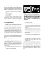
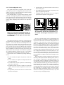
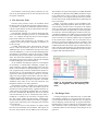
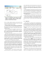
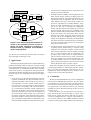
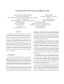
Prototyping with a bio-inspired reconfigurable chip
Yann Thoma and Eduardo Sanchez
Logic Systems Laboratory
Swiss Federal Institute of Technology of Lausanne (EPFL)
Lausanne, Switzerland
[email protected], [email protected]
Carl Hetherington
Dept. of Electronics
University of York
York, UK
[email protected]
Daniel Roggen
Autonomous Systems Laboratory
EPFL
Lausanne, Switzerland
[email protected]
Juan-Manuel Moreno
Dept. of Electronic Engineering
Technical University of Catalunya (UPC)
Barcelona, Spain
[email protected]
Abstract
In this paper we explain how the POEtic chip can be used
for rapid prototyping. The POEtic chip, currently in the test
phase, is a system-on-chip (SoC) containing a microprocessor and a reconfigurable array. Special features allow the
dynamic creation of data paths in the reconfigurable array
at runtime. It has been specially designed to ease the development of bio-inspired systems such as neural networks,
but can serve as a general purpose platform, or as a prototype for hardware/software codesign. An AMBA bus allows POEtic chips to be connected to each other, or to external devices. After describing the hardware SoC, we discuss the software tools that have been created to design and
test different applications. Three of these applications are
described in order to demonstrate the utility of the POEtic
chip’s special features.
1. Introduction
In recent years, bio-inspiration has been more and more
important in the design of electronic and software systems.
Artificial neural networks take care of sorting mail by analyzing human handwriting [16], while new antenna shapes
are developed using genetic algorithms [8]. Designers can
draw inspiration from the three life axes: Phylogeny (evolution), Ontogenesis (development), and Epigenesis (learning).
The Phylogenetic axis (P) represents the way in which
species evolve, and how parents share their genetic heritage
to create a new individual. The neo-Darwinian theory is now
used by developers to solve complex problems for which no
deterministic method can be found. Genetic algorithms [6]
are based on a selection from a population of individuals
representing potential solutions, using a fitness function depending on the problem being solved. The selected individuals share their genotype to create a new generation by applying cross-over and mutation. The process is repeated until an acceptable solution is found.
The Ontogenetic axis (O) corresponds to the development of an organism from its first cell, the zygote, and to
the self-healing capabilities of living beings. No machine
or computer is capable of the self-repair seen in nature, although such a capability would be very useful for many situations such as space exploration, where humans cannot
intervene. In a real organism, every cell contains the entire genome, allowing cells to self-repair without any global
control. Some artificial systems, for example the embryonics project [9], use the same principles to make an artificial
organism out of many identical cells that can differentiate
and self-repair.
On the Epigenetic axis (E) we find the learning capabilities of living beings, based on neural networks. Our brain,
or even a fly’s brain, is capable during its life of acquiring
a lot of experience. Furthermore, these learned experiences
have an effect on the organism’s behaviour. Artificial neural
networks [17] are based on these principles, and their purpose is to develop systems that can, for example, learn to
execute a task or recognize a pattern.
There has been considerable research involving one or
more of these three life-axes. Most of it is done in software,
due to the lack of a real hardware platform specifically designed for such applications. However, hardware implementations can dramatically improve the speed of genetic algorithms, evolvable hardware, and neural networks, by taking
advantage of the inherent parallelism of hardware systems.
The POEtic [12] chip [10] is a new reconfigurable hardware platform for rapidly prototyping bio-inspired systems
that employ POE principles. In this paper we describe three
applications which take advantage of the special features of
POEtic, to show its potential for prototyping. These special
features can be summarized as:
POEtic tissue
organic subsystem
environmental subsystem
out
processor
out
AMBA
system
interface
out
LUT
• parallel configuration
• partial reconfiguration
• dynamic routing
The next section briefly describes the POEtic hardware
platform. Section 3 discusses the microprocessor programming tools, while section 4 describes the reconfigurable
hardware development tools. We then show some applications that are currently being developed on this platform,
before concluding.
16x16
booth
multiplier
16-bit
timer
LUT
partial
lut[0]
lut[1]
lut[2]
lut[3]
lut[4]
lut[5]
lut[6]
lut[7]
lut[8]
lut[9]
lut[10]
lut[1
1]
lut[12]
lut[13]
lut[14]
lut[15]
LUT
partial
lut[0]
lut[1]
lut[2]
lut[3]
lut[4]
lut[5]
lut[6]
lut[7]
lut[8]
lut[9]
lut[10]
lut[1
1]
lut[12]
lut[13]
lut[14]
lut[15]
LUT
partial
lut[0]
lut[1]
lut[2]
lut[3]
lut[4]
lut[5]
lut[6]
lut[7]
lut[8]
lut[9]
lut[10]
lut[1
1]
lut[12]
lut[13]
lut[14]
lut[15]
LUT
partial
lut[0]
lut[1]
lut[2]
lut[3]
lut[4]
lut[5]
lut[6]
lut[7]
lut[8]
lut[9]
lut[10]
lut[1
1]
lut[12]
lut[13]
lut[14]
lut[15]
partial
lut[0]
lut[1]
lut[2]
lut[3]
lut[4]
lut[5]
lut[6]
lut[7]
lut[8]
lut[9]
lut[10]
lut[1
1]
lut[12]
lut[13]
lut[14]
lut[15]
LUT
partial
lut[0]
lut[1]
lut[2]
lut[3]
lut[4]
lut[5]
lut[6]
lut[7]
lut[8]
lut[9]
lut[10]
lut[1
1]
lut[12]
lut[13]
lut[14]
lut[15]
LUT
partial
lut[0]
lut[1]
lut[2]
lut[3]
lut[4]
lut[5]
lut[6]
lut[7]
lut[8]
lut[9]
lut[10]
lut[1
1]
lut[12]
lut[13]
lut[14]
lut[15]
LUT
partial
lut[0]
lut[1]
lut[2]
lut[3]
lut[4]
lut[5]
lut[6]
lut[7]
lut[8]
lut[9]
lut[10]
lut[1
1]
lut[12]
lut[13]
lut[14]
lut[15]
LUT
partial
lut[0]
lut[1]
lut[2]
lut[3]
lut[4]
lut[5]
lut[6]
lut[7]
lut[8]
lut[9]
lut[10]
lut[1
1]
lut[12]
lut[13]
lut[14]
lut[15]
LUT
partial
lut[0]
lut[1]
lut[2]
lut[3]
lut[4]
lut[5]
lut[6]
lut[7]
lut[8]
lut[9]
lut[10]
lut[1
1]
lut[12]
lut[13]
lut[14]
lut[15]
LUT
partial
lut[0]
lut[1]
lut[2]
lut[3]
lut[4]
lut[5]
lut[6]
lut[7]
lut[8]
lut[9]
lut[10]
lut[1
1]
lut[12]
lut[13]
lut[14]
lut[15]
LUT
partial
lut[0]
lut[1]
lut[2]
lut[3]
lut[4]
lut[5]
lut[6]
lut[7]
lut[8]
lut[9]
lut[10]
lut[1
1]
lut[12]
lut[13]
lut[14]
lut[15]
LUT
partial
lut[0]
lut[1]
lut[2]
lut[3]
lut[4]
lut[5]
lut[6]
lut[7]
lut[8]
lut[9]
lut[10]
lut[1
1]
lut[12]
lut[13]
lut[14]
lut[15]
LUT
partial
lut[0]
lut[1]
lut[2]
lut[3]
lut[4]
lut[5]
lut[6]
lut[7]
lut[8]
lut[9]
lut[10]
lut[1
1]
lut[12]
lut[13]
lut[14]
lut[15]
LUT
• combination of a microprocessor and a reconfigurable
array
out
partial
lut[0]
lut[1]
lut[2]
lut[3]
lut[4]
lut[5]
lut[6]
lut[7]
lut[8]
lut[9]
lut[10]
lut[1
1]
lut[12]
lut[13]
lut[14]
lut[15]
LUT
partial
lut[0]
lut[1]
lut[2]
lut[3]
lut[4]
lut[5]
lut[6]
lut[7]
lut[8]
lut[9]
lut[10]
lut[1
1]
lut[12]
lut[13]
lut[14]
lut[15]
Figure 1. The POEtic chip, showing the microprocessor and the reconfigurable array. In
the organic subsystem, the molecular plane
(bottom) is connected to the routing plane
(top). Many elements connected to the AMBA
bus, (another timer and serial and parallel
ports) are omitted in order to simplify the
schematics.
2. The POEtic Platform
• Every instruction is 32 bits.
The POEtic chip has been specifically designed to ease
the development of bio-inspired applications. It is composed of two main parts: a microprocessor, in the environmental subsystem, and a 2-dimensional reconfigurable array called the organic subsystem (figure 1). This array is
made of small elements, called molecules, that are essentially composed of a 4-input look-up table and a flip-flop.
Although being oriented for bio-inspired systems, its architecture makes it a good candidate for any general design
as the microprocessor can access the reconfigurable array
very rapidly. This can be useful for both configuration and
state retrieval.
A test chip containing the microprocessor and twelve
molecules is currently being manufactured. This ASIC prototype uses a CMOS 0.35 µm 1P-5M technology. Based on
this prototype, the final chip will be designed and then realized.
• Every instruction is executed in one clock cycle.
2.1. The Microprocessor
The microprocessor is a 32-bit RISC processor, specifically designed for the POEtic chip. Its purpose is to control the organic subsystem, including the configuration of
molecules, as well as to execute evolutionary processes.
During the design process, particular attention was paid to
the microprocessor size so as to leave more room for the reconfigurable array.
The main features of the POEtic microprocessor are as
follows:
• The architecture is LOAD/STORE.
• A five-stage pipeline implements the datapath, with
the following states: Fetch, Decode, Execute, Memory,
and Writeback.
• 57 instructions are defined, two of which give access to
a hardware pseudo-random number generator (a read
instruction, and the load of an initial seed) which can
be very useful for evolutionary processes. This generator has been implemented using a 32-bit linear feedback shift register.
• Up to 5 interrupt sources can be handled by the microprocessor.
• An AMBA bus [3] allows communication with all internal elements, as shown in figure 1, as well as with
external devices. It also permits the interconnection of
many POEtic chips, in order to realize a bigger virtual
reconfigurable array.
The microprocessor can configure the array, and also retrieve its state. Access is made in parallel, so configuration
and partial reconfiguration are very fast. The retrieved state
can be used to calculate the fitness of an individual, in the
case of an evolutionary process, or simply to debug any design running on POEtic. For genetic algorithms, evolution
can be performed by the microprocessor. This obviates the
need for slow data transmission to and from a host computer.
2.2. The Reconfigurable Array
The organic subsystem is composed of two layers: the
molecular layer, that is reconfigured by the microprocessor,
and the routing layer which implements a dynamic routing
algorithm managed by the molecules.
The molecular layer is a grid of basic elements, called
molecules. Although being similar to standard FPGA elements, molecules have special features which are useful for
bio-inspired systems. The main components are a 4-input
look-up table, a flip-flop, and a switch box, as depicted in
figure 2.
Figure 2. On the left, 9 molecules of the reconfigurable array. In the centre, a molecule
in 4-LUT mode. On the right, the switch box
of a molecule.
The switch box allows the connection of molecules that
are not adjacent to one another. It is composed of eight multiplexers — two in each direction. Each multiplexer can select from the two signals coming from each direction, the
output of the molecule, or a second output. The second output is, in most cases, the inverse of the first. The switch box
has been designed with multiplexers, rather than with antifuse or RAM bits, in order to avoid any short-circuit. This
feature means that a developer can use POEtic as platform
for evolvable hardware without any risk, as no randomly
generated bitstream configuration can destroy the chip.
The molecule can act in different operating modes (figure 3):
• In 4-LUT mode, the output is any function of the four
inputs.
• In 3-LUT mode, two outputs are computed, each from
any 3-input function.
• In Comm mode, the LUT is split into a 8-bit shift register and a 3-input LUT.
• In Memory mode, the LUT is used as a 16-bit shift
register, and can be used to implement a serial access
memory.
• In Input mode, the molecule retrieves a value from the
dynamic routing layer.
• In Output mode, the molecule sends a value to the dynamic routing layer.
• In Configure mode, the molecule can partially reconfigure a neighbouring molecule.
• In Trigger mode, the molecule serves as a trigger to
synchronize the dynamic routing process.
Figure 3. 3 bits define the operational mode
of a molecule. On the left, a molecule in 4LUT mode. On the right, a molecule in 3-LUT
mode.
One of the special features of the reconfigurable array
is that molecules can be partially reconfigured without microprocessor intervention. A molecule configuration is described by 76 bits, split into 5 blocks. The molecule can
allow a reconfiguration of each of its blocks, and chooses
the source of the configuration data. A partial reconfiguration is processed when a molecule in Configure mode is active; this is when its first input is active. In this state, configuration bits are shifted on every clock cycle, with the second input of the Configure molecule being sent out as the
new configuration bitstream. This feature allows LUT content or dynamic routing addresses to be changed at runtime.
It can be very useful for self-repair systems, in which the array can partially reconfigure itself without needing an external agent.
The routing layer is a grid of routing units, which can dynamically create paths between different points of the circuit at runtime. It implements a distributed dynamic routing algorithm, based on addresses (interested readers can
see a description of this algorithm in [14]). It can be used to
create connections between any parts of the circuit, by using the input/output molecules. In a cellular system (e.g. a
neural network), for instance, cells could be identified by
a unique ID and then connected to other cells by means of
this mechanism. As the path creation is made at runtime,
and can be made incrementally, POEtic is a very good architecture on which to grow neural networks, or any other
system involving a changing topology.
The hardware circuit having been presented, we now
look at the development tools for the microprocessor and
the organic subsystem.
3. The Processor Tools
The first of the processor tools is an assembler which
has been written to test the microprocessor design. Like every assembler, it translates an ASCII description to machine
code in a simple manner. It has been derived from the WinTim32 meta-assembler [2].
The assembler, although very useful for developing efficient code and for testing the processor, is not ideal for end
users. A C compiler derived from the LCC meta-compiler
[5] has been realized as an alternative.
The machine code generated by the assembler or the
compiler can be run by either a simulator, an emulator, or
by the real chip.
A VHDL description of the microprocessor has been
used to create the electronic layout of the chip. These
VHDL files also serve to simulate the microprocessor when
used with Modelsim [1], a tool to simulate and debug hardware designs. The machine code can be put into a VHDL
file describing the processor ROM, and compiled in Modelsim. The result of the simulation is a waveform which exactly mimics the processor’s signals, and this can be helpful
in understanding the processor architecture.
As the simulator only displays signals in a chronogram,
its usefulness is reduced when simulating complex programs. Therefore, after the VHDL model of the CPU was
frozen, a CPU emulator was designed (figure 4). It executes
CPU programs using a software model which decodes instructions one by one and updates the variables representing the CPU state (registers, memory content, etc.) accordingly. The CPU programs execute faster when the CPU is
emulated, because the emulator does not resort to the more
complex VHDL models. Speedups compared to the VHDL
simulation of the order of 10 to 100 were observed, even
though the emulator is not fully optimized.
The emulator provides a graphical user interface which
shows the status of the CPU. The code window shows the
instructions in the program memory, together with their opcodes and the corresponding comments that were placed in
the source assembler file. Breakpoints can be set and the
code executed line by line or continuously until either a
breakpoint is reached or the execution is stopped manually. The register window and the memory window show
the content of the registers and the CPU memory, highlighting the entries which have been changed by the execution
of an instruction.
The current version of the emulator can import output
files from the WinTim32 meta-assembler, and support for
the LCC meta-compiler will be added in the near future.
The emulator can export the program in a VHDL ROM file
for subsequent verification using VHDL simulation. Export
in the COE format, which is used by the Xilinx memory
synthesis tools, is also supported and can be used to initialize the content of the program ROM when synthesizing the
CPU on an FPGA.
Plugins, in the form of DLLs, can be included to emulate memory mapped peripherals. When the CPU reads or
writes memory locations which correspond to the address
space of a plugin, the corresponding functions of the DLL
are called. This offers the opportunity to emulate peripherals of the SoC without modifying the emulator. In this way,
a peripheral emulating an UART (Universal Asynchronous
Receiver/Transmitter) has been implemented. When characters are written to its memory address, they are displayed
in the console of the emulator. This is a convenient way of
displaying program information from the assembler code
in a way which is fully compatible with a SoC using a real
UART. Further DLLs have been written to interface the emulator with the molecule design tools described in the next
sections. These DLLs allow simultaneous execution of CPU
programs and molecular hardware.
Figure 4. The emulator, showing assembler
code, the registers, and the memory contents.
4. The Design Tools
Creating a design for the molecular array is a more difficult task than compiling a C program for the microprocessor. Development tools are an important way of easing the
task of designing a molecular array. A program called POEticMol allows creation of designs at the molecular level
and visualization of the system during a simulation, while
a schematic editor lets the developer create designs at the
gate level.
Figure 5. The graphical user interface of
POEticMol, showing the configuration of 6
molecules.
4.1. Molecular Design
POEticMol provides a graphical interface (figure 5) for
configuration of the molecules by hand. The user sees all the
molecules, and can specify every configuration option via a
dialog (figure 6). In addition, molecules can be grouped in
order to ease the visualization of complex systems.
The inter-molecular communication is done through
switch boxes, and manual configuration of these switch
boxes would be tedious. A basic router has been incorporated, which requires the developer only to click
on a source and a target. A path is automatically created through the switch boxes, using a breadth-first search
algorithm to find the shortest path between the two points.
Initially, POEticMol was conceived as a prototype to
ease the debugging phase of the organic subsystem. It was
a good tool to visualize the state of the molecules and routing units, and has changed a lot since the first version of the
chip. Now that the chip is fixed, it is widely used to create new designs.
4.2. Schematic Editor
The POEticMol tool presents the designer with a lowlevel view of the POEtic IC. An additional tool, schemed,
offers the option of a higher-level design process.
Rather than operating in terms of molecules, the frontend to schemed allows users to draw circuits based on a collection of high-level ‘components’, such as counters, triggers and logic gates. The software can then synthesize an ar-
Figure 6. The dialog in which the user can describe the entire molecular configuration.
ray of POEtic molecules to implement a particular circuit.
The molecular array is passed to the POEticMol tool, from
which the synthesized molecules can be examined and simulated in the normal way. In addition, schemed collects the
results of any simulations that are run and presents the results on the schematic.
Schemed also presents some other useful tools for
schematic designers. Firstly, a set of components and interconnections can be grouped together into a new
user-defined component. Such a component might be a design for a simple neuron, for example. The inputs and
outputs of this new component can be named as appropriate in order to make their purpose clear. These user-defined
components can then be used in other schematics, allowing a library of useful components to be constructed and
re-used.
The schemed editor (figure 7) consists of two main parts:
the front end, which handles the graphical user interface,
and the back end, which can convert high-level schematics
into molecules.
The front end is written in C++ using the wxWidgets
class library. It presents a typical schematic editing interface
with which users can connect ‘components’ using ‘wires’.
The various properties of the components (e.g. number of
Figure 7. A schematic editor allows the rapid
creation of designs which can then be exported as a molecular structure.
cally sorted based on their interconnections. Then, the arrangement of molecules required for each component is
found. The required molecule arrangements are then laid
out onto the tissue using a simple snake-like placement algorithm.
Once molecules have been placed on the tissue, the last
step is to implement their interconnections using the switch
boxes that are a part of each molecule. A connection between two molecules is constructed using Dijkstra’s shortest path algorithm, and the switch boxes on the path are configured appropriately.
At present, there is no optimisation or re-try step if routing fails. Such techniques are currently under development.
The result of the synthesis is a set of molecules which are
written to disk in the format used by POEticMol. This tool
can then be used to view the results of the schemed synthesis.
4.3. Simulation
bits in a counter, number of inputs to a logic gate) can be
set up using dialogue boxes. Schematics can be saved and
loaded in a simple text-based format.
The back end has the task of taking a set of components
and interconnections, and generating the appropriate POEtic molecules. The process can be divided into five stages:
simplification, logic synthesis, component synthesis, placement and routing.
Firstly, the schematic is simplified in some basic ways.
Groups of components are expanded into their constituent
parts. Connections between other connections are simplified, so that all connections go between one component’s
output and another’s input.
Secondly, any logic gates within the circuit are collected
together. Logic gates are different from most other component types in that several gates can be synthesized using a
single POEtic molecule; all other component types require
an integer number of molecules for their implementation.
The logic gates in the circuit are collapsed into the smallest
suitable number of 4-input, 1-output look-up tables; such
LUTs can be synthesized directly into molecules.
The third step is to synthesize the molecules that are required for each component. Each component type has an algorithm to generate the required molecules, and these algorithms can be dependent on parameters of the component.
For example, there are several different ways of implementing a trigger component, and the optimal implementation
depends on the number of clock cycles that is required between trigger pulses. Schemed can use the trigger ‘length’
that the designer has specified in order to choose the optimal trigger representation.
Following synthesis is the process of placing components within the tissue. Firstly, components are topographi-
The test phase is a crucial part of any system design, allowing developers to find and fix errors. POEticMol simulates the entire organic subsystem using its VHDL description. This description has been used to create the electronic
layout of the final chip, and so reflects exactly the real chip
behaviour.
Figure 8 shows every component involved in a simulation (software, DLLs, files). Modelsim, a digital designs
simulator, is launched by POEticMol, and simulates the organic subsystem. A Foreign Language Interface, supplied
by Modelsim, allows the VHDL code to be interfaced with
a windows DLL written in C or C++. Using this mechanism,
we defined a special component (POEticvhdl.dll) which interfaces the simulation and the graphical user interface of
POEticMol using a pipe file. The simulation and the GUI
can therefore communicate, with the GUI controlling the
simulation and retrieving its state.
Inputs/Outputs to the simulation are controlled by a separate DLL, called POEtic io.dll, that can be rewritten by
the developer. It allows the forcing of inputs and the retrieval of outputs in order, for example, to interface with
another piece of software like a robot simulator, or to write
data into a file. A DLL function is called every clock cycle, allowing the control of inputs/outputs with high level
functions supplied by the programmer.
During a simulation, the GUI displays the state of the
molecules and routing units, either together or separately.
In this way, the developer has a global view on the entire
system, either step by step or after any number of clock cycles.
Furthermore, if the design has been developed with the
schematic editor, a pipe file allows the DLL loaded by Modelsim to send simulation values to the schematic. In this
cessor and the reconfigurable array, three features not
present in commercial FPGAs.
Depends on the application
Khepera create Pipe
Simulator
file
General architecture
for simulation
Pipe create Schematic
file
Editor
connect
POEtic_
io.dll
connect
Pipe
file
load
load
POEtic_
vhdl.dll
ModelSim
start
connect
create
POEtic load POEtic
software create project
load
update
VHDL
files
Figure 8. The different programs and files involved in the simulation process. In this example, the VHDL simulation is linked to a
Khepera robot [7] simulator and schematic
editor using pipe files.
way, the user can visualize the molecule states corresponding to the higher-level design’s state.
5. Applications
Although specially designed for bio-inspired cellular applications, the POEtic chip’s architecture is general enough
for the implementation of any type of application that needs
a microprocessor to communicate closely with a reconfigurable array. However, the applications that have been developed for the POEtic chip thus far are all bio-inspired systems. We now go on to briefly describe three of these applications.
• A PO tissue [11], that brings Phylogenetic and Ontogenetic mechanisms into play, has already been designed for the POEtic chip. Its purpose is to use a genetic algorithm to evolve a cellular system where every cell can act as a 3-input function. Evolution deals
with the cells’ functionality, and with the connectivity, by exploiting the dynamic routing capabilities of
the circuit. Evolution is done by the microprocessor,
while the ontogenetic part, that is the development of
the system starting from a single cell, is executed in
the organic subsystem. This application takes advantage of the dynamic routing (so that the organism can
grow), the partial reconfiguration to differentiate cells,
and of the rapid communication between the micropro-
• Evolvable hardware (EHW), on the Phylogenetic axis,
deals with the design of analog or digital circuits using genetic algorithms. This technique replaces the design engineer with an algorithm, and can be used in
many different areas (e.g. robot control). POEtic can
be used as a platform for evolvable hardware, reproducing the work of Thompson [15], in a faster manner. A very fast way of evolving the configuration
stream of POEtic has been developed [13], and will
be tested with the chip as soon as it is available. Compared to commercially-available FPGAs, POEtic will
be the best solution for solving these kind of problems for two reasons. Firstly the microprocessor, on
the same chip as the reconfigurable array, can rapidly
change the configuration. Secondly, the implementation of the molecules, being based only on multiplexers, allows unconstrained evolution by ensuring that
short circuits cannot occur.
• As a third example, on the Epigenetic axis, a new kind
of spiking neuron, defined in [4], is currently being
mapped to the molecules of POEtic. These neurons
have learning capabilities, and are capable of taking
care of a robot navigation task, by recognizing vertical lines with a linear camera. A single neuron has
now been tested, and will serve to create a neural network. The routing layer, a feature that does not exist
in common FPGAs, will serve to connect neurons together, and the microprocessor will be used to evolve
neuron parameters such as synaptic weights.
These three examples show the potential of POEtic as
a prototyping platform for bio-inspired systems. Furthermore, its on-chip microprocessor, with access to the configuration bits of the reconfigurable array, makes it an excellent tool for various other applications.
6. Conclusion
We have presented the POEtic chip, a new reconfigurable
circuit with an embedded microprocessor. We have shown
its usefulness for bio-inspired systems, and described features which are important for the rapid prototyping of various applications. The different software tools currently
available have been described, showing the ease of use of
this new circuit.
In the near future, the microprocessor tools and the organic subsystem tools will be merged, in order to allow
rapid tests of systems that involve both the microprocessor and a reconfigurable part, using the entire POEtic tissue. For these systems, a total VHDL simulation could be
performed, involving the VHDL description of both parts.
As an alternative, the processor emulator will be linked to
the VHDL simulation of the organic subsystem, to give an
excellent visualization of the microprocessor and molecule
states. This new tool will allow the rapid creation and test
of new designs for POEtic, without any need for a real circuit.
When the final chip is available, the new tool will be
used to visualize the state of the real circuit, showing the
molecules and the routing units state gathered by communication with the microprocessor.
6.1. Acknowledgements
This project is funded by the Future and Emerging Technologies programme (IST-FET) of the European Community, under grant IST-2000-28027 (POETIC). The information provided is the sole responsibility of the authors and
does not reflect the Community’s opinion. The Community
is not responsible for any use that might be made of data
appearing in this publication. The Swiss participants to this
project are supported under grant 00.0529-1 by the Swiss
government.
References
[1] http://www.model.com/products/default.asp.
[2] http://users.ece.gatech.edu/˜hamblen/book/wintim.
[3] ARM.
AMBA
Specification,
Rev
2.0.
Advanced
RISC
Machines
Ltd
(ARM),
http://www.arm.com/armtech/AMBA Spec, 1999.
[4] J. Eriksson, O. Torres, A. Mitchell, G. Tucker, K. Lindsay,
D. Halliday, J. Rosenberg, J.-M. Moreno, and A. E. P. Villa.
Spiking neural networks for reconfigurable POEtic tissue. In
A. Tyrrell, P. Haddow, and J. Torresen, editors, Evolvable
Systems: From Biology to Hardware. Proc. 5th Int. Conf.
on Evolvable Hardware (ICES 03), volume 2606 of LNCS,
pages 165–173, Berlin, 2003. Springer-Verlag.
[5] D. Hanson and C. Fraser. A Retargetable C Compiler: Design and Implementation. Benjamin-Cummings Publishing
Company, 1995.
[6] J. Holland. Genetic algoritms and the optimal allocation of
trails. In SIAM Journal of Computing, volume 2:2, pages
88–105, 1973.
[7] K-TEAM S.A. Khepera User Manual. Préverenges, Switzerland (http://www.k-team.com).
[8] D. S. Linden. Optimizing signal strength in-situ using an
evolvable antenna system. In A. Stoica, J. Lohn, R. Katz,
D. Keymeulen, and R. S. Zebulum, editors, The 2002
NASA/DoD Conference on Evolvable Hardware, pages 147–
151, Alexandria, Virginia, 15-18 July 2002. Jet Propulsion
Laboratory, California Institute of Technology, IEEE Computer Society.
[9] D. Mange, M. Sipper, A. Stauffer, and G. Tempesti. Towards
robust integrated circuits: The embryonics approach. In Proceedings of the IEEE, volume 88:4, pages 516–541, April
2000.
[10] J.-M. Moreno, Y. Thoma, E. Sanchez, O. Torres, and G. Tempesti. Hardware realization of a bio-inspired POEtic tissue.
In Proc. 2004 NASA/DoD Conference on Evolvable Hardware, Seattle, USA. To be published.
[11] D. Roggen and Y. Thoma. An evolving and developing cellular electronic circuit. In Ninth International Conference on
the Simulation and Synthesis of Living Systems (ALIFE9),
Boston, Massachusetts, USA. To be published.
[12] E. Sanchez, D. Mange, M. Sipper, M. Tomassini, A. PerezUribe, and A. Stauffer. Phylogeny, ontogeny, and epigenesis:
Three sources of biological inspiration for softening hardware. In T. Higuchi, M. Iwata, and W. Liu, editors, Evolvable Systems: From Biology to Hardware, volume 1259 of
LCNS, pages 33–54, Berlin, 1997. Springer-Verlag.
[13] Y. Thoma and E. Sanchez. A reconfigurable chip for evolvable hardware. In Proc. Genetic and Evolutionary Computation COnference (GECCO 2004), Seattle, USA. To be published.
[14] Y. Thoma, E. Sanchez, J.-M. Moreno Arostegui, and G. Tempesti. A dynamic routing algorithm for a bio-inspired reconfigurable circuit. In P. Y. K. Cheung, G. A. Constantinides, and J. T. de Sousa, editors, Proc. of the 13th International Conference on Field Programmable Logic and Applications (FPL’03), volume 2778 of LNCS, pages 681–690,
Berlin, Heidelberg, 2003. Springer Verlag.
[15] A. Thompson. On the automatic design of robust electronics through artificial evolution. In M. Sipper, D. Mange, and
A. Pérez-Uribe, editors, ICES’98, volume 1478 of Lecture
Notes in Computer Science, pages 13–24, Berlin Heidelberg,
1998. Springer-Verlag.
[16] L. S. Yaeger, J. B. Webb, and R. F. Lyon. Combining neural
networks and context-driven search for online, printed handwriting recognition in the newton. A.I. Magazine, 19(1):73–
89, 1998.
[17] J. Zhu and P. Sutton. FPGA implementations of neural networks - a survey of a decade of progress. In P. Y. K. Cheung,
G. A. Constantinides, and J. T. de Sousa, editors, Proc. of
the 13th International Conference on Field Programmable
Logic and Applications (FPL’03), number 2778 in LNCS,
pages 1062–1066, Berlin, Heidelberg. Springer Verlag.