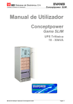
1
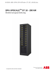
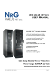
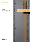
Conceptpower DPATM Technical Specifications Conceptpower DPA™ highlights at a glance ¾ DPA with Safe-Swap Modules (SSM) For premium power protection availability ¾ Low total Cost of Ownership (TCO) Cost saving during entire life-cycle ¾ Flexibility/Scalability Ease of power upgrade, pay as you grow ¾ Enhanced Serviceability Rapid fault recovery ¾ Link to NewavewatchTM Instantaneous fault recognition Safe-Swap Modular Power Protection Power range: 8-200KW per rack Specifications are subject to change without notice Edition 31.03.2009 Section-10 TABLE OF CONTENTS 10.1 CONCEPTPOWER DPA SYSTEM DESCRIPTION...................................................................................3 10.2 TECHNICAL CHARACTERISTICS ............................................................................................................4 10.2.1 MECHANICAL CHARACTERISTICS MD-FRAMES AND MODULES..................................................4 10.2.2 MECHANICAL CHARACTERISTICS MX-FRAMES AND MODULES ..................................................5 10.2.3 POWER SELECTION TABLE CONCEPTPOWER DPA MODULES.....................................................6 10.3 INPUT CHARACTERISTICS ......................................................................................................................6 10.3.1 GRAPH: INPUT PF VERSUS % LOAD..................................................................................................7 10.3.2 GRAPH: INPUT DISTORTION THDI VERSUS % LOAD.......................................................................7 10.4 BATTERY CHARACTERISTICS................................................................................................................8 10.5 OUTPUT CHARACTERISTICS ..................................................................................................................8 10.5.1 GRAPH: AC – AC EFFICIENCY with Linier load @ cosphi 1 ................................................................9 10.5.2 GRAPH: Output Power in KW and KVA VERSUS cosphi.....................................................................9 10.6 ENVIRONMENTAL CHARACTERISTICS ...............................................................................................10 10.7 STANDARDS............................................................................................................................................10 10.8 COMMUNICATION ...................................................................................................................................11 10.8.1 POWER MANAGEMENT DISPLAY (PMD)..........................................................................................11 10.8.2 MIMIC DIAGRAM..................................................................................................................................11 10.8.3 DISPLAY ...............................................................................................................................................11 10.8.4 CUSTOMER INTERFACES (Terminals X1….X4)...............................................................................12 10.8.5 CUSTOMER INPUTS DRY PORT s: Terminal block X1......................................................................12 10.8.6 CUSTOMER OUTPUTS DRY PORTs : Terminal blocks X2, X3, X4 ..................................................12 10.9 OPTIONS ..................................................................................................................................................13 10.9.1 MODEM/ETHERNET CARD / NewavewatchTM MANAGEMENT SOFTWARE ...................................13 10.9.2 SNMP card / WaveMon Management Software ..................................................................................14 10.9.3 BATTERY CABINETS ..........................................................................................................................14 10.10 BATTERY AUTONOMIES........................................................................................................................15 10.10.1 MD Modules: Examples of Internal Battery Autonomy....................................................................15 10.10.2 MD Modules: Examples of External Battery Autonomy ..................................................................15 10.10.3 MX Modules: Examples of Internal Battery Autonomy....................................................................16 10.10.4 MX Modules : Examples of External Battery Autonomy................................................................16 10.11 INSTALLATION PLANNING ....................................................................................................................17 10.11.1 HEAT DISSIPATION PER MODULE WITH NON-LINEAR LOAD...................................................17 10.12 WIRING AND BLOCK DIAGRAMS FOR ALL FRAMES AND MODULES.............................................18 10.12.1 TERMINAL CONNECTIONS OVERVIEW .......................................................................................18 10.12.2 SINGLE FEED INPUT ......................................................................................................................19 10.12.3 DUAL FEED INPUT..........................................................................................................................20 www.newaveups.com 00-8384_S10_NW_TDSDPA_GB_090331.DOC Printed in Switzerland – Modifications reserved Page 2/20 Section-10 10.1 CONCEPTPOWER DPA SYSTEM DESCRIPTION In environments that demand zero downtime, continuous power protection availability is essential. In order to respond to today’s dynamic IT and process-related environments that experience daily change through new server technologies, migration and centralization, resilient and easily adaptable power protection concepts are required. CONCEPTPOWER DPA is the foundation for continuous power protection availability of network-critical infrastructures in enterprise data centers where business continuity has paramount importance and in process control environment where manufacturing continuity is essential. NEWAVE CONCEPTPOWER DPA’S is a second generation high-power-density (HPD), leading-edge double-conversion power protection technology that has standardized on a modular component approach which helps speed deployment, improve adaptability and increase system availability while reducing total cost of ownership. CONCEPTPOWER DPA’S is a unique on-demand architecture that integrates the power rack, power distribution unit, back-up battery rack and monitoring and management solutions to allow easy selection of optimized configurations. CONCEPTPOWER DPA’S (Distributed Parallel Architecture) provides highest availability, unmatched flexibility and at the same time lowest cost of ownership in IT environments. This Technical Specification provides detailed technical information on the mechanical, electrical and environmental performance of the CONCEPTPOWER DPA that can support to give answers to tender and end-user requirements. The CONCEPTPOWER DPA was designed to respond to the most stringent safety, EMC and other important UPS standards. CONCEPTPOWER DPA is a rack-mountable modular design. It offers 6-types of Racks (Frames) and 7 types of DPA-Modules to accommodate a wide range of power requirements. The three MD-Frames; Classic DPA-25, Triple DPA-75, Upgrade DPA-150 can accommodate the four (4) MD-DPA-Modules types DPA 10 or 15 or 20 or 25 of: 10kVA/8kW - 15kVA/12kW - 20kVA/16kW 25kVA/20kW power, whereas The three MX-Frames; Classic DPA-50, Triple DPA-150, Upgrade DPA-250 can accommodate the three (3) MX-DPA-Modules types DPA 30 or 40 or 50 of: 30kVA/24kW - 40kVA/32kW - 45kVA/40kW power. Key Features of CONCEPTPOWER DPA : • Highest Availability Modular, Decentralized Parallel Architecture (DPA) Near-zero down time • High Power Density (up to 342kW / m2), Small Footprint Space-saving of expensive floor space • Unity Output Power Factor (KW=KVA) Full power for loads with unity PF No de-rating for loads with Unity PF • Blade-server-friendly power Full power from 0.9 lead to 0.8 lag No de-rating with leading PF loads • Highest Efficiency even with partial loads Efficiency = 91 - 95.5% for loads 25-100% Energy cost saving during UPS-life-cycle (depending on Module power and type of load) • Very low input current distortion THDi THDi = < 2 - 3% for loads of 100 – 25 % Gen-set power and installation cost saving www.newaveups.com 00-8384_S10_NW_TDSDPA_GB_090331.DOC Printed in Switzerland – Modifications reserved Page 3/20 Section-10 10.2 TECHNICAL CHARACTERISTICS 10.2.1 MECHANICAL CHARACTERISTICS MD-FRAMES AND MODULES CONCEPTPOWER DPA CLASSIC DPA-25 TRIPLE DPA-75 UPGRADE DPA-125 MD - FRAMES Configuration accommodates: Max. 1 module (10-25kVA) and 200 x 7/9Ah batteries 3 modules (10-25kVA) and 180 x 7/9Ah batteries 5 modules (10-25kVA) and no batteries Max. Power connection kVA 25 75 125 Dimensions (WxHxD) mm 550x1650x780 550x1975x780 550x1975x780 kg 180 218 171 kg 209 up to 215 (with 1 Module) 304 up to 323 (with 3 Modules) 314 up to 346 (with 5 Modules) Weight of Empty Frame w/o modules and w/o batteries Weight of Frame with modules and w/o batteries Colours Front door silver :RAL 9007 + NEWAVE black (inlets) Side walls/top: Graphite grey (Pulverlacke No. 4222903402 serie 09RCCAT1) MD- DPA MODULES DPA 10 DPA 15 DPA 20 DPA 25 Output Apparent Rated Power KVA 10 15 20 25 Output Active Rated Power KW 8 12 16 20 8/8 12 / 12 16 /16 20 /20 30 – 50 30 – 50 30 – 50 40 - 50 Output Power with Load PF=1 KVA / KW Variable Number of 12V Battery Blocks No. Dimensions (WxHxD) mm Weight UPS Module kg Colours 483 x 225 x 700 28.5 31 33 35 Front : Graphite grey (Pulverlacke No. 4222903402 serie 09RCCAT1) www.newaveups.com 00-8384_S10_NW_TDSDPA_GB_090331.DOC Printed in Switzerland – Modifications reserved Page 4/20 Section-10 10.2.2 MECHANICAL CHARACTERISTICS MX-FRAMES AND MODULES CONCEPTPOWER DPA CLASSIC DPA-50 TRIPLE DPA-150 UPGRADE DPA-250 MX - FRAMES Configuration accommodates: Max. 1 module (30-45kVA) and 280 x 7/9Ah batteries 3 modules (30-45kVA) and 240x 7/9Ah batteries 5 modules (30-45kVA) and no batteries Max. Power connection kVA 50 150 250 Dimensions (WxHxD) mm 730x1650x800 730x1975x800 730x1975x800 kg 262 239 205 kg 306 up to 318 (with 1 Module) 371 up to 407 (with 3 Modules) 425 up to 485 (with 5 Modules) Weight of Empty Frame w/o modules and w/o batteries Weight of Frame with modules and w/o batteries Colours Front door silver :RAL 9007 + NEWAVE black (inlets) Side walls/top: Graphite grey (Pulverlacke No. 4222903402 serie 09RCCAT1) MX- DPA MODULES DPA 30 DPA 40 DPA 50 Output Apparent Rated Power KVA 30 40 45 1) Output Active Rated Power KW 24 32 40 KVA / KW 24 / 24 32 / 32 40 /40 Variable Number of 12V Battery Blocks No. 40-50 40-50 40-50 Dimensions (WxHxD) mm Weight UPS Module kg Output Power with Load PF=1 663 x 225 x 720 44 53 56 Front : Graphite grey (Pulverlacke No. 4222903402 serie Colours 09RCCAT1) 1) On Inverter mode 50 KVA/40kW on Bypass mode 45 KVA/40kW www.newaveups.com 00-8384_S10_NW_TDSDPA_GB_090331.DOC Printed in Switzerland – Modifications reserved Page 5/20 Section-10 10.2.3 POWER SELECTION TABLE CONCEPTPOWER DPA MODULES Conceptpower DPA: Power Modules DPA 10 - DPA 50 50 Conceptpower DPA modules Cosphi 1.0 45 40 Conceptpower DPA modules Cosphi 0.8 40.0 kVA 45.0 kVA 40.0 kW 40.0 KW kW / kVA 35 32.0 kW 30 30.0 kVA 25.0 kVA 25 20.0 kVA 24.0 kW 20 20.0 kW 16.0 kW 15 10 5 10 kVA 8.0 kW 0 DPA DPA DPA DPA DPA DPA DPA Module Types 10 15 20 25 30 40 50 MD Modules 20.0 kW 16.0 kW 15.0 kVA 12.0 kW MX Modules 32.0 kW 24.0 kW kVA KW 12.0 kW 8.0 kW DPA DPA DPA DPA DPA DPA DPA 10 15 20 25 30 40 50 MD Modules MX Modules 10.3 INPUT CHARACTERISTICS Module Range MD Module Type Output Rated Power per Module cosφ 0.8 Output Rated Power per Module cosφ 1.0 Nominal Input Voltage kVA KW V Input Voltage Tolerance (ref to 3x400/230V) for Loads in %: V Input Frequency Hz MX DPA 10 DPA 15 DPA 20 DPA 25 DPA 30 DPA 40 DPA 50 10 8 15 12 20 16 25 20 30 24 40 32 45 1) 40 3x380/220V+N, 3x400V/230V+N, 3x415/240V+N (-23%/+15%) 3x308/177 V to 3x460/264 V for <100 % load (-30%/+15%) 3x280/161 V to 3x460/264 V for < 80 % load (-40%/+15%) 3x240/138 V to 3x460/264 V for < 60 % load 35 – 70 PF=0.99 @ 100 % load Input Power Factor A Inrush Current limited by soft start / max. In Sine-wave THDi = < 2 % @ 100% load Input Distortion THDI Max. Input Power with rated output power and charged battery per Module kW 8.5 12.8 17.0 21.3 25.4 33.9 42.9 A 12.3 18.5 24.7 30.8 36.8 49.1 62.1 kW 9.3 14.0 18.6 23.3 27.8 37.1 46.9 A 13.5 20.2 27.0 33.7 40.3 53.7 68.0 (output Cosφ = 1.0) Max. Input Current with rated output power and charged battery per Module (output Cosφ = 1.0) Max. Input Power with rated output power and discharged battery per Module (output Cosφ = 1.0) Max. Input Current with rated output power and discharged battery per Module (output Cosφ = 1.0) 1) On Inverter mode 50 KVA/40kW on Bypass mode 45 KVA/40kW www.newaveups.com 00-8384_S10_NW_TDSDPA_GB_090331.DOC Printed in Switzerland – Modifications reserved Page 6/20 Section-10 10.3.1 GRAPH: INPUT PF VERSUS % LOAD Input Power Factor In p u t P o w er facto r (L ead in g ) 1 0 .9 2 0 .8 0 .9 8 0 .9 6 0 .9 9 0 .6 0 .4 0 .2 0 25 50 75 100 Load % 10.3.2 GRAPH: INPUT DISTORTION THDI VERSUS % LOAD Input THDi % In p u t C u rre n t D is to rtio n T H D i 6 .0 5 .5 5 .0 4 .5 4 .0 3 .5 3 .0 2 .5 2 .0 1 .5 3 .4 2 .4 25 50 Load 2 .3 75 2 .0 100 % www.newaveups.com 00-8384_S10_NW_TDSDPA_GB_090331.DOC Printed in Switzerland – Modifications reserved Page 7/20 Section-10 10.4 BATTERY CHARACTERISTICS Module Range MD Module Type Variable Number of 12V Battery Blocks No. Maximum Battery Charger Current MX DPA 10 DPA 15 DPA 20 DPA 25 DPA 30 DPA 40 DPA 50 30-50 30-50 30-50 40-50 40-50 40-50 40-50 6A Standard (10 A optional) A Battery Charging Curve 10A Standard (15 A optional) Ripple free ; IU (DIN 41773) Temperature compensation Standard (temp. sensor optional) Battery Test Automatic and periodically (adjustable) Battery Type Maintenance free VRLA or NiCd 10.5 OUTPUT CHARACTERISTICS Module Range MD DPA 10 Module Type Output Rated Power per Module Output Rated Power per Module Output Current In @ cosphi 1.0 (400 V) Output Rated Voltage kVA KW A V Output Voltage Stability % Output Voltage Distortion % Output Frequency Hz Output Frequency Tolerance % Bypass operation Permissible Unbalanced Load (All 3 phases regulated independently) Phase Angle Tolerance (With 100 % Unbalanced load) % Deg. DPA 15 DPA 20 MX DPA 25 DPA 30 DPA 40 DPA 50 15 20 25 30 40 45 1) 12 16 20 24 32 40 17.4 23.2 29 35 46.5 58 3x380/220V or 3x400/230V or 3x415/240V Static: < +/- 1% Dynamic (Step load 0%-100% or 100%-0%) < +/- 4% With Linear Load < 1.5% With Non-linear Load (EN62040-3:2001) < 2% 50 Hz or 60 Hz Synchronized with mains < +/- 2 % (selectable for bypass operation) or < +/- 4 % Free running +/- 0.1 % At Nominal Input voltage of 3x400 V +/- 15% or 190 V to 264 V ph-N 10 8 11.6 100% +/- 0 deg. Overload Capability on Inverter % 125 % load 150 % load Output short capability (RMS) A Inverter : Bypass : Crest - Factor 10 min. 60 sec. 2 x In during 250 ms 10 x In during 10 ms 3:1 1) On Inverter mode 50 KVA/40kW on Bypass mode 45 KVA/40kW www.newaveups.com 00-8384_S10_NW_TDSDPA_GB_090331.DOC Printed in Switzerland – Modifications reserved Page 8/20 Section-10 10.5.1 GRAPH: AC – AC EFFICIENCY with Linier load @ cosphi 1 Efficiency up to 1 % higher with output PF cosphi 0.8 Details refer to paragraph 10.7 Environmental Characteristics 100 95 90 85 80 75 70 % L in e a r L o a d (c o s p h i= 1 ) 94 9 3 .5 91 9 4 .5 94 D P A 3 0 -5 0 D P A 1 0 -2 5 25 10.5.2 GRAPH: 9 4 .5 94 93 50 75 Load 100 % Output Power in KW and KVA VERSUS cosphi 50 40 44 42 40 37 42 50 44 47 38 31 30 kVA kW 100 % kW 20 10 0 36 32 -0.85 -0.90 -0.95 1.00 0.95 0.90 0.85 0.80 0.75 0.70 0.60 kVA 37 44 42 40 42 44 47 50 50 50 50 kW 31 40 40 40 40 40 40 40 38 36 32 cap Cosphi 40 30 20 10 0 Output Power in kVA Output Power in kW DPA 50 Output Power versus cosphi ind Ind. Cap. Fig. AC-AC Efficiency of DPA 50 Module cosφ 0.85 0.90 0.95 1.00 0.95 0.90 0.85 0.80 0.75 0.70 0.60 DPA10 kW kVA 6.2 7.3 8 8.9 8 8.4 8 8 8 8.4 8 8.9 8 9.4 8 10 7.6 10 7.2 10 6.3 10 MD Module Range DPA15 DPA20 kW kVA kW kVA 9.3 11 12.3 14.5 12 13.3 16 17.8 12 12.6 16 16.8 12 12 16 16 12 12.6 16 16.8 12 13.3 16 17.8 12 14.1 16 18.8 12 15 16 20 11.4 15 15.3 20 10.8 15 14.5 20 9.5 15 12.7 20 DPA25 kW kVA 15.4 18.1 20 22.2 20 21.1 20 20.0 20 21.1 20 22.2 20 23.5 20 25 19.1 25 18.1 25 15.9 25 MX Module Range DPA30 DPA40 DPA50 1) kW kVA kW kVA kW kVA 18.5 21.8 24.6 29 31 36.5 24 26.7 32 35.6 40 44.4 24 25.3 32 33.7 40 42.1 24 24 32 32.0 40 40 24 25.3 32 33.7 40 42.1 24 26.7 32 35.6 40 44.4 24 28.2 32 37.6 40 47.1 24 30 32 40 40 501) 22.9 30 30.5 40 38 501) 21.7 30 28.9 40 36 501) 19 30 25.4 40 32 501) 1) DPA 50 : On Inverter Mode 50 KVA/40kW on Bypass Mode 45 KVA/40kW Changes of this table without notice – modifications reserved www.newaveups.com 00-8384_S10_NW_TDSDPA_GB_090331.DOC Printed in Switzerland – Modifications reserved Page 9/20 Section-10 10.6 ENVIRONMENTAL CHARACTERISTICS Module Range MD DPA 10 DPA 40 DPA 50 dBA 55/49 57/49 57/49 57/49 59/51 65/55 65/55 Module Type Audible Noise with 100% / 50% Load DPA 15 MX DPA 20 DPA 25 DPA 30 Operation temperature °C 0 – 40 Ambient Temperature for Batteries (recommended) °C 20 – 25 Storage Temperature °C -25 - +70 Battery Storage Time at Ambient Temperature Max. 6 months Max. altitude (above sea level) m 1000m (3300ft) without de-rating De-rating factor for use at altitudes above 1000m sea level according ( IEC 62040-3) Meter above sea level (m / ft) De-Rating Factor for Power 1500 / 4850 2000 / 6600 2500 / 8250 3000 / 9900 0.95 0.91 0.86 0.82 Max. 95% (non-condensing) Relative Air-humidity Accessibility Totally front accessibility for service and maintenance (no need for side, top or rear access) Positioning Min. 20 cm rear space (required for fan) Input and Output Power Cabling From the bottom on the front Efficiency AC-AC up to (at cosphi 1.0) (depending on Module power) Load : DPA 30-50 : DPA 10-25 : % Efficiency with Linear Load at cosφ =0.8ind Efficiency Non-linear Load (EN 62040-1-1:2003) Eco-Mode efficiency at 100% load 100 % 94.5% 94% 75 % 94.5% 94% 50% 94% 93.5% 25% 93% 91% Typically up to 1 % higher of above values Typically up to 1 % lower of above values % 98 % 10.7 STANDARDS Safety Electromagnetic Compatibility EMC Classification IEC/EN 62040-1-1, IEC/EN 60950-1 IEC/EN 61000-6-4 (product standard IEC/EN 62040-2 limit A (C2 UPS)) IEC/EN 61000-6-2 (product standard IEC/EN 62040-2 Criterion A (C2 UPS)) IEC/EN 61000-4-2, IEC/EN 61000-4-3, IEC/EN 61000-4-4, IEC/EN 61000-4-5, IEC/EN 61000-4-6 DPA-10 DPA-15 DPA-20 DPA-25 DPA-30 DPA-40 DPA-50 Emission Class C1 C1 C1 C2 C2 C2 C2 Immunity Class C1 C2 C2 C3 C3 C3 C3 Performance IEC/EN 62040-3 Product certification CE Degree of protection IP 20 www.newaveups.com 00-8384_S10_NW_TDSDPA_GB_090331.DOC Printed in Switzerland – Modifications reserved Page 10/20 Section-10 10.8 COMMUNICATION Power Management Display (PMD) 1 LCD display for each module Serial ports RS232 on Sub-D9 2x system frame + 1x on each module (Smart Port) For monitoring and integration in network management USB 1x For monitoring and software management Customer Interfaces : Inputs DRY PORT X1 1 Remote Shut down [EMERGENCY OFF (Normally closed)] 1 GEN-ON (Normally open) 2 Programmable Customer’s Inputs (Normally open) 1 Temp. Sensor for Battery Control Customer Interfaces : Outputs DRY PORT X2 , X3, X4 10 voltage free contacts For remote signalling and automatic computer shutdown Slot for SNMP SNMP card (optional) For monitoring and integration in network management Slot for Newavewatch TM Newavewatch TM card (optional) for Premium Power Protection 10.8.1 POWER MANAGEMENT DISPLAY (PMD) The user-friendly PMD consists of three parts the MIMIC DIAGRAM, CONTROL KEYS and LCD that provides the necessary monitoring information about the UPS. 10.8.2 MIMIC DIAGRAM The mimic diagram serves to give the general status of the UPS. The LED-indicators show the power flow status and in the event of mains failure or load transfer from inverter to bypass and vice-versa the corresponding LED-indicators will change colour from green (normal) to red (warning). The LED’s LINE 1 (rectifier) and LINE 2 (bypass) indicate the availability of the mains power supply. The LED’s INVERTER and BYPASS if green indicate which of the two are supplying power to the critical load. When the LEDindicator BATTERY is lit it means that the battery due to mains failure is supplying the load. The LEDindicator ALARM is a visual indication of any internal or external alarm condition. At the same time the audible alarm will be activated. 10.8.3 DISPLAY The 2 x 20 character LCD simplifies the communication with the UPS. The menu driven LCD enables the access to the EVENT REGISTER, or to monitor the input and output U, I, f, P, Autonomy Time and other Measurement’s, to perform commands like start-up and shut-down of INVERTER or load transfer from INVERTER to BYPASS and vice-versa and finally it serves for the DIAGNOSIS (SERVICE MODE) for adjustments and testing (for more details see the USER MANUAL of Conceptpower DPATM). Power Management Display (PMD) of Conceptpower DPM TM www.newaveups.com 00-8384_S10_NW_TDSDPA_GB_090331.DOC Printed in Switzerland – Modifications reserved Page 11/20 Section-10 10.8.4 CUSTOMER INTERFACES (Terminals X1….X4) 10.8.5 CUSTOMER INPUTS DRY PORT s: Terminal block X1 Connection of Remote Shut down facilities, Generator Operation, Customers specials (see UM Section 9 / OPTIONS) 10.8.6 CUSTOMER OUTPUTS DRY PORTs : Terminal blocks X2, X3, X4 Provision of signals for the automatic and orderly shutdown of servers, AS400 or Automation building systems All voltage free contacts are rated 60 VAC max. and 500 mA max.: All the interfaces are connected to Phoenix Spring terminals with wires : 0.5 mm2 Block X1 X2 X3 X4 Terminal Contact Signal X1 / 1 IN X1 / 2 GND X1 / 3 IN X1 / 4 GND X1 / 5 IN X1 / 6 GND X1 / 7 IN X1 / 8 GND X1 / 9 IN X1 / 10 GND X2 / 1 NO X2 / 2 NC X2 / 3 C X2 / 4 NO X2 / 5 NC X2 / 6 C X2 / 7 NO X2 / 8 NC X2 / 9 C X2 / 10 NO X3 / 1 NC X3 / 2 C X3 / 3 NO X3 / 4 NC X3 / 5 C X3 / 6 NO X3 / 7 NC X3 / 8 C X3 / 9 NO X3 / 10 NC X4 / 1 C X4 / 2 NO X4 / 3 NC X4 / 4 C X4 / 5 NO X4 / 6 NC X4 / 7 C X4 / 8 NO X4 / 9 NC X4 / 10 C On Display Function + 3.3 Vdc Remote Shut down GND (Do not remove the factory mounted bridge until external Remote Shut down is connected) + 3.3 Vdc Generator Operation GND (NC = Generator ON) + 3.3 Vdc Customer IN 1 GND (Function on request, to be defined) + 3.3 Vdc Customer IN 2 GND (Function on request, to be defined) + 3.3 Vdc Temperature Battery GND (If connected , the battery charger current if depending of the battery temp.) MAINS_OK ALARM Mains Present Mains Failure Common LOAD_ON_INV Message Load on Inverter (Load on Mains bypass) Common BATT_LOW ALARM Battery Low Battery OK Common LOAD_ON_MAINS Message Load on bypass (Mains) (Load on Inverter) Common COMMON_ALARM ALARM Common Alarm (System) NO Alarm Condition Common MODUL_ALARM1 ALARM Module 1 Alarm NO Alarm Condition Common MODUL_ALARM2 ALARM Module 2 Alarm NO Alarm Condition Common MODUL_ALARM3 ALARM Module 3 Alarm NO Alarm Condition Common MODUL_ALARM4 ALARM Module 4 Alarm NO Alarm Condition Common MODUL_ALARM5 ALARM Module 5 Alarm NO Alarm Condition Common Phoenix Spring Terminals (X1…X4) Connection www.newaveups.com 00-8384_S10_NW_TDSDPA_GB_090331.DOC Printed in Switzerland – Modifications reserved Page 12/20 Section-10 10.9 OPTIONS - Modem/Ethernet card or Modem/GSM card for NewavewatchTM Management Software - SNMP card and WaveMon Management Software , Modbus Protocol - External Battery Cabinets - Parallel bus for additional frames - In/Output Transformator for special voltages - Battery Chargers - Temp. sensor for battery temp. control 10.9.1 MODEM/ETHERNET CARD / NewavewatchTM MANAGEMENT SOFTWARE NewavewatchTM is a redundant remote monitoring and management service which is a part of the Premium Power Protection Concept, providing you with peace-of-mind protection, knowing the mission critical facility is under careful, continuous watch 24/7/365. There are two different solution cards Modem/Ethernet or Modem/GSM to connect the UPS to the outside world. Continuous monitoring is an affordable insurance policy to detect and warn before they become a crisis. Acquire key performance parameter and productivity information in real-time to empower you with the details needed to better understand machine performance and faster troubleshoot downtime events. Early warning system, so problems can be addressed before they become a real threat to the load. Professional experts, your virtual service technician onside. Total transparency of information and actions performed like Notification of all critical status changes, Coordination of equipment service, Reporting of all alarms with priorities. What are the features? • Redundant and secure communication • Alarm acknowledgment • Priority driven Management (with escalation) Comprehensive Management System – Reception and management of alarm calls from UPS – Storage of UPS Data in a database exportable in a CVS-format for easy handling in Excel – Unlimited number of UPS that can be managed – User administration with passwords and permission-level – Administration of Log file – Data logging with statistical analysis and diagnostics, report Visualization of the UPS data: • Current status (“single” and “parallel” operation) • Measured values for single or three phase • Recording function including graphs with zooming capabilities for selected measured values • Display of event log file • Display of UPS Parameters • Web Server functionality, for data access from any Web Browser UPS-System 1….1000 Management Station SSL INTERNET Redundant Interface Card 1 … .1 MODEM Call back AlarmSituation Communication Interface Modem GSM Modem Network interface (ethernet) MODEM Communication Interface INTERNET www.newaveups.com 00-8384_S10_NW_TDSDPA_GB_090331.DOC Printed in Switzerland – Modifications reserved Page 13/20 Section-10 10.9.2 SNMP card / WaveMon Management Software The Simple Network Management Protocol (SNMP) is a worldwide-standardized communication-protocol. It is used to monitor any device in the network via simple control language. The UPS-Management Software WaveMon also provides its data in this SNMP format with its internal software agent. The operating system you are using must support the SNMP protocol. We offer our WaveMon software with SNMP functionality for Novell, OS/2, all Windows running on INTEL and ALPHA, DEC VMS, Apple. Two types of SNMP interfaces with identical functionality are available: an external SNMP-Adapter (Box) and an internal SNMP-Card. Both can manage a parallel system (N modules) and return either global values - which are consistent for the whole parallel system - or specific values from the single modules. UPS External SNMP-Adapter 9 Ethernet Internal SNMP-Card 10.9.3 BATTERY CABINETS S-type = For Separate. Battery C-type = For Common. Battery CBAT-DPA-120 CBAT-DPA-200 S-type or C-type S-type or C-type 120 Batt. block x 24Ah/28Ah on 8 shelf 3x5=15 blocks/shelf 200 Batt. blocks x 24Ah/28Ah on 7 shelf 6x5=30 blocks/shelf BATTERY FRAMES Configuration accommodates: Max. 3/3 5/5 (Terminal 9 x 16/25mm2) (Terminal 15 x 16/25mm2) Battery fuses / Max. Batt. Strings : Terminals : S-type Battery fuses / Max. Batt. Strings Terminals : 3/3 5/5 C-type + Com. Connection Bar 3 x (2xM8) +PE 2xM8 + Com. Connection Bar 3 x (2xM10) +PE 2xM10 A 3x100 A 5x100A Dimensions (WxHxD) mm 730x1975x800 1200x1975x800 Weight with trays and w/o batteries kg 290 410 Battery Configurations 30x28Ah 40x28Ah 50x28Ah (2x30)x28Ah (2x40)x28Ah (2x50)x28Ah (3x30)x28Ah (3x40)x28Ah Battery Configurations (2x40)x28Ah (3x40)x28Ah (4x40)x28Ah (5x40)x28Ah (2x50)x28Ah (3x50)x28Ah (4x50)x28Ah (5x30)x28Ah (5x40)x28Ah Fuse Type (Very Fast acting) Possible Battery configurations within the Battery Cabinets www.newaveups.com 00-8384_S10_NW_TDSDPA_GB_090331.DOC Printed in Switzerland – Modifications reserved Page 14/20 Section-10 10.10 BATTERY AUTONOMIES 10.10.1 MD Modules: Examples of Internal Battery Autonomy Module Type DPA 10 DPA 15 Separate Battery configuration Frame Type (up to 3 modules / within Triple-75 frame) 10kVA/8KW 15kVA/12KW 8 / 14 5/8 11 / 18 7 / 11 14 / 23 8 / 14 Common Battery configuration CLASSIC DPA-25 or TRIPLE DPA-75 CLASSIC DPA-25 or TRIPLE DPA-75 CLASSIC DPA-25 or TRIPLE DPA-75 CLASSIC DPA-25 or TRIPLE DPA-75 ONLY for CLASSIC DPA-25 With 2 Modules DPA 25 Battery Autonomy in (min.) per Module Battery / Module CLASSIC DPA-25 40x7Ah / 9Ah or TRIPLE DPA-75 CLASSIC DPA-25 50x7Ah / 9Ah or TRIPLE DPA-75 CLASSIC DPA-25 (2x30)x7Ah / 9Ah or TRIPLE DPA-75 With 1 Module DPA 20 20KVA/16KW 25KVA/20KW 6/9 Battery Autonomy in (min.) for Tot. System Power Module Type 1 x DPA 10 1 x DPA 15 1 x DPA 20 1 x DPA 25 Total System Power 10kVA/8KW 15kVA/12KW 20KVA/16KW 25KVA/20KW (2x40)x7Ah / 9Ah 21 / 33 12 / 20 8 / 14 6 / 10 (2x50)x7Ah / 9Ah 28 / 43 16 / 26 11 / 18 8 / 14 (3x40)x7Ah / 9Ah 35 / 54 21 / 33 14 / 23 11 / 23 (3x50)x7Ah / 9Ah 47 / 1h 12` 28 / 43 19 / 30 14 / 23 (4x50)x7Ah / 9Ah 1h 09’ / 1h 44` 41 / 1h 02` 28 / 43 21 / 33 Module Type 2 x DPA 10 2 x DPA 15 2 x DPA 20 2 x DPA 25 30kVA/24KW 5/8 40kVA/32KW 50kVA/40KW TRIPLE DPA-75 (2x40)x7Ah / 9Ah 20kVA/16KW 8 / 14 TRIPLE DPA-75 (2x50)x7Ah / 9Ah 11 / 18 7 / 11 TRIPLE DPA-75 (3x40)x7Ah / 9Ah 14 / 23 8 / 14 TRIPLE DPA-75 (3x50)x9Ah 30 18 13 9 3 x DPA 10 3 x DPA 15 3 x DPA 20 3 x DPA 25 45kVA/36KW 60kVA/48KW 75kVA/60KW 8 6 With 3 Modules Total System Power Module Type TRIPLE DPA-75 (2x40)x7Ah / 9Ah 30kVA/24KW 5/8 TRIPLE DPA-75 (2x50)x7Ah / 9Ah 7 / 11 TRIPLE DPA-75 (3x40)x7Ah / 9Ah 8 / 14 5/8 TRIPLE DPA-75 (3x50)x9Ah 18 11 Total System Power 6/9 10.10.2 MD Modules: Examples of External Battery Autonomy This configuration are mostly used in combination with the frame UPGRADE DPA-125 Module Type DPA 10 DPA 15 Separate Battery configuration Battery Cabinet (for up to 5 modules linked) Battery / Module DPA 20 DPA 25 Battery Autonomy in (min.) per Module 30x28Ah 10kVA/8KW 37 15kVA/12KW 22 20KVA/16KW 15 25KVA/20KW 1x CBAT-DPA-200 1x CBAT-DPA-200 40x28Ah 54 32 22 17 Common Battery configuration With 4 Modules Module Type Total System Power Battery Autonomy in (min.) for Tot. System Power (4+1) 4 x DPA 10 4 x DPA 15 4 x DPA 20 4 x DPA 25 40kVA/32KW 12 60kVA/48KW 80kVA/64KW 100kVA/80KW 1x CBAT-DPA-120 50x28Ah 1x CBAT-DPA-120 (2x50)x28Ah 30 18 12 9 1x CBAT-DPA-120 (3x40)x28Ah 37 22 15 12 1x CBAT-DPA-200 (3x50)x28Ah 50 30 21 15 1x CBAT-DPA-200 (4x50)x28Ah 72 43 30 22 www.newaveups.com 00-8384_S10_NW_TDSDPA_GB_090331.DOC Printed in Switzerland – Modifications reserved Page 15/20 Section-10 10.10.3 MX Modules: Examples of Internal Battery Autonomy DPA 30 Module Type Separate Battery configuration Frame Type Battery / Module (up to 3 modules / within Triple-150 frame) Common Battery configuration CLASSIC DPA-50 CLASSIC DPA-50 CLASSIC DPA-50 CLASSIC DPA-50 CLASSIC DPA-50 With 2 Modules TRIPLE DPA-150 TRIPLE DPA-150 With 3 Modules TRIPLE DPA-150 DPA 50 Battery Autonomy in (min.) per Module CLASSIC DPA-50 (2x40)x9Ah or TRIPLE DPA-150 With 1 Module DPA 40 30kVA/24KW 40KVA/32KW 8 6 45KVA/40KW Battery Autonomy in (min.) for Tot. System Power Module Type Total System Power (2x50)x9Ah (3x40)x9Ah (3x50)x9Ah (4x50)x9Ah (5x50)x9Ah Module Type Total System Power 2x(2x40)x9Ah 3x(2x40)x9Ah Module Type Total System Power 3x(2x40)x9Ah 1 x DPA 30 30kVA/24KW 11 14 18 26 34 2 x DPA 30 60kVA/48KW 8 14 3 x DPA 30 90kVA/72KW 8 1 x DPA 40 40KVA/32KW 8 9 13 18 24 2 x DPA 40 80kVA/64KW 1 x DPA 50 45KVA/40KW 9 3 x DPA 40 120kVA/96KW 6 7 3 x DPA 50 135kVA/120KW DPA 40 DPA 50 9 14 18 2 x DPA 50 90kVA/80KW 10.10.4 MX Modules : Examples of External Battery Autonomy This configuration are mostly used in combination with the frame UPGRADE DPA-250 DPA 30 Module Type Separate Battery configuration Battery Cabinet (for up to 5 modules linked) Battery Autonomy in (min.) per Module Battery / Module 1x CBAT-DPA-200 40x28Ah Common Battery configuration Module Type With 4 Modules Total System Power (3x40)x28Ah 1x CBAT-DPA-120 (3x50)x28Ah 1x CBAT-DPA-200 (4X50)x28Ah 1x CBAT-DPA-200 5x (2x40) x 28Ah 2x CBAT-DPA-200 30kVA/24KW 40KVA/32KW 45KVA/40KW 13 9 7 Battery Autonomy in (min.) for Tot. System Power (4+1) 4 x DPA 30 4 x DPA 40 4 x DPA 50 120kVA/96KW 160kVA/128KW 180kVA/160KW 9 6 12 9 18 12 9 43 30 22 www.newaveups.com 00-8384_S10_NW_TDSDPA_GB_090331.DOC Printed in Switzerland – Modifications reserved Page 16/20 Section-10 10.11 INSTALLATION PLANNING Clearances Minimum X Y 200mm 900 mm X X Battery Cabinet UPS Frames Open Doors Y UPS Frames Y Open Doors Figure 1: UPS space recommendation Figure 2 : : UPS + Battery space recommendation CLASSIC DPA-25 TRIPLE DPA-75 UPGRADE DPA-125 550x1650x780 550x1975x780 550x1975x780 CLASSIC DPA-50 TRIPLE DPA-150 UPGRADE DPA-250 730x1650x800 730x1975x780 730x1975x800 Battery Cabinet Type NA CBAT DPA-120 CBAT DPA-200 Dimensions (WxHxD) mm NA 730x1975x800 1200x1975x800 UPS Frame type (25kVA up to 125 kVA) Dimensions (WxHxD) mm UPS Frame type (50kVA up to 250 kVA) Dimensions (WxHxD) mm Accessibility Totally front accessibility for service and maintenance (no need for side, top or rear access) Positioning Min. 20 cm rear space (required for fan) Input and Output Power Cabling From the bottom on the front 10.11.1 HEAT DISSIPATION PER MODULE WITH NON-LINEAR LOAD Module size MD Module Type MX DPA 10 DPA 15 DPA 20 DPA 25 DPA 30 DPA 40 DPA 50 Heat Dissipation with 100% Non-linear Load per Module (EN 62040-1-1:2003) W 600 900 1200 1500 1670 2225 2780 Heat Dissipation with 100% Non-linear Load per Module (EN 62040-1-1:2003) BTU 2047 3070 4094 5118 5698 7592 9485 Airflow (25° - 30°C) with Non-linear Load per Module (EN 62040-1-1:2003) m3/h 150 150 150 150 380 380 380 www.newaveups.com 00-8384_S10_NW_TDSDPA_GB_090331.DOC Printed in Switzerland – Modifications reserved Page 17/20 Section-10 10.12 WIRING AND BLOCK DIAGRAMS FOR ALL FRAMES AND MODULES The customer has to supply the wiring to connect the UPS to the local power source. The installation inspection and initial start up of the UPS and extra battery cabinet must be carried out by a qualified service personnel such as a licensed service engineer from the manufacturer or from an agent authorised by the manufacturer. More details and procedure are mentioned in the user manual. 10.12.1 TERMINAL CONNECTIONS OVERVIEW FRAME TYPE Terminals (T) Connection Bar (B) Separate. Battery Common Battery (+ / N / - ) +PE (+ / N / - ) +PE 2 3+1 x 16/25mm (T) CLASSIC DPA-25 2 TRIPLE DPA-75 9+1 x 16/25mm (T) UPGRADE DPA-125 15+1 x 16/25mm (T) CLASSIC DPA-50 3+1 x 16/25mm (T) 2 2 3+1 x 16/25mm (T) Input Bypass Input Rectifier Output load 3+N 3+N+PE 3+N+PE 2 4 x 10/16mm (T) 3 x M6 (B) 2 +PE 1 x 16mm (T) 4 x 35/50mm (T) 3 x M10 (B) 2 +PE 1 x 50mm (T) 4 x 70/95mm (T) 2 4 x 35/50mm (T) 2 +PE 50 mm (T) 2 4 x 70/95mm (T) 2 + PE 50mm (T) 2 4 x 35/50mm (T) 2 +PE 50 mm (T) 4 x 70/95mm (T) 2 + PE 50mm (T) 2 2 2 3+1 x 16/25mm (T) 4 x 16/25mm (T) 5 x 16/25mm (T) 5 x 16/25mm (T) 2 3 x M10 (B) +PE 1xM10 (B) 3 x M10(B) +PE 1xM10 (B) 4 x M10 (B) +PE 1xM10 (B) 4 x M10 (B) +PE 1xM10 (B) 3 x M12 (B) +PE 1xM12 (B) 3 x M12 (B) +PE 1xM12 (B) 4 x M12 (B) +PE 1xM12 (B) 4 x M12 (B) +PE 1xM12 (B) 9+1 x 16/25mm (T) +PE 1xM10 (B) UPGRADE DPA-250 15 x 16/25mm (T) +PE 1xM12 (B) 2 2 5 x 10/16mm (T) 2 2 TRIPLE DPA-150 2 2 2 5 x 10/16mm (T) CLASSIC DPA-25 CLASSIC DPA-50 TRIPLE DPA-75 TRIPLE DPA-150 Upgrade DPA-125 UPGRADE DPA-250 Dual feed input 2 Single feed input www.newaveups.com 00-8384_S10_NW_TDSDPA_GB_090331.DOC Printed in Switzerland – Modifications reserved Page 18/20 Section-10 10.12.2 SINGLE FEED INPUT Cable Sections and Fuse Ratings recommended. Alternatively, local standards to be respected F1 F2 Rectifier Inverter Static Switch Frame F1 F2 UPS module 2…4 Inverter F1 F2 UPS module 1 Rectifier Cable E Fuse E STANDARD VERSION (SINGLE FEED INPUT) MAINS 3x400/230V Rectifier Inverter Static Switch IA2-1 UPS module 5 Fuse Cable A Static Switch IA2-2..4 IA2-5 Maintenance Bypass IA1 Cable D Load 3x400/230 V Input 3x400V Frame type Load kVA cosphi 0.8 Fuse A (Agl/CB) Output 3x400V cosphi 0.8 Max. Input Current 2 Cable A (mm ) with battery (IEC 60950-1:2001) charging (A) Battery 2 2 Cable D (mm ) (IEC 60950-1:2001) I nom (A) Fuse E +/N/(Agl/CB) Cable E (mm ) for CBAT DPA 120 or 200 ONLY +/N/Com. Battery Sep. Battery MD Frames (Frames shall be cabled to there full rating capability) CLASSIC DPA-25 TRIPLE DPA-75 UPGRADE DPA-125 25 3x63A 5x10 34 5x10 36 A 3x63A*1 3x10 3x10 75 3x125A 5x50 101 5x50 108 A 3x160A*1 3x50 3x (3x10) 125 3x225A 5x95 169 5x95 181 A 3x260A*1 3x120 5x (3x10) MX Frames (Frames shall be cabled to there full rating capability) CLASSIC DPA 50 TRIPLE DPA-150 UPGRADE DPA-250 50 3x100A 5x25 67 5x25 72 A 3x100A*1 3x25 3x25 150 3x250A 5x120 or 5x(2x50) 202 5x120 or 5x(2x50) 218 A 3x300A*1 3x150 3x (3x25) 250 3x400A 5x(2x95) 337 5x(2x95) 362 A 3x500A*1 3x(2x150) 5x (3x25) Other intermediate Ratings (we recommend to cable the frame mentioned above at full rating to able future upgrading) 10 15 20 30 40 45 60 80 90 100 120 160 200 3x20A 3x25A 3x40A 3x63A 3x80A 3x100A 3x100A 3x125A 3x160A 3x160A 3x200A 3x250A 3x315A 5x2.5 5x4 5x6 5x10 5x25 5x25 5x25 5x50 5x50 5x50 5x70 5x120 or 5x(2x50) 5x185 or 5x(2x70) 13 20 27 40 54 68 81 108 121 135 161 215 267 5x2.5 5x4 5x6 5x10 5x25 5x25 5x25 5x50 5x50 5x50 5x70 5x120 or 5x(2x50) 5x185 or 5x(2x70) 14 A 22 A 29 A 43 A 58 A 65 A 87 A 116 A 130 A 145 A 174 A 232 A 290 A 3x32A 3x63A 3x63A 3x80A 3x100A* 3x125A* 3x125A* 3x160A* 3x200A* 3x224A* 3x250A* 3x350A* 3x450A* 3x4 3x10 3x10 3x16 3x25* 3x35* 3x35* 3x50* 3x70* 3x95* 3x120* 3x(2x70)* 3x(2x95)* *1 only valid for common battery use www.newaveups.com 00-8384_S10_NW_TDSDPA_GB_090331.DOC Printed in Switzerland – Modifications reserved Page 19/20 Section-10 10.12.3 DUAL FEED INPUT Cable Sections and Fuse Ratings recommended. Alternatively, local standards to be respected Fuse C Cable C F1 F2 Inverter Rectifier Inverter Static Switch Frame UPS module 2…4 UPS module 1 Cable E Fuse E F1 F2 F1 F2 Rectifier Rectifier Inverter Module Static Switch Static Switch IA2-1 VERSION (DUAL FEED INPUT) MAINS 3x400/230V UPS module 5 Fuse B Cable B IA2-5 IA2-2..4 Maintenance Bypass IA1 Cable D MAINS 3x400/230V Input 3x400V Frame type Load kVA cosphi 0.8 Fuse B (Agl/CB) Bypass 3x400V 2 Cable B (mm ) (IEC 609501:2001) Max. Input Current Fuse C with battery (Agl/CB) charging (A) Output 3x400V cosphi 0.8 Cable C 2 (mm ) Cable D 2 (mm ) (IEC 609501:2001) (IEC 609501:2001) Battery 2 I nom Fuse E +/N/(Agl/CB) Cable E (mm ) for CBAT DPA 120 or 200 ONLY +/N/Com. Battery Sep. Battery 3x10 MD Frames (Frames shall be cabled to there full rating capability) CLASSIC DPA-25 TRIPLE DPA75 UPGRADE DPA-125 25 3x63A 5x10 34 3x63A 4x10 5x10 36 A 3x63A*1 3x10 75 3x125A 5x50 101 3x125A 4x50 5x50 108 A 3x160A*1 3x50 125 3x225A 5x95 169 3x225A 4x95 5x95 181 A 3x260A*1 3x120 3x (3x10) 5x (3x10) MX Frames (Frames shall be cabled to there full rating capability) CLASSIC DPA 50 TRIPLE DPA150 UPGRADE DPA-250 50 3x100A 5x25 67 3x100A 4x25 5x25 72 A 3x100A*1 3x25 5x120 or 5x(2x50) 218 A 3x300A*1 3x150 5x(2x95) 362 A 3x500A*1 3x(2x150) 150 3x250A 5x120 or 5x(2x50) 202 3x250A 4x120 or 4x(2x50) 250 3x400A 5x(2x95) 337 3x400A 4x(2x95) 3x25 3x (3x25) 5x (3x25) Other intermediate Ratings (we recommend to cable the frame mentioned above at full rating to able future upgrading) 10 15 20 30 40 45 60 80 90 100 120 3x20A 3x25A 3x40A 3x63A 3x80A 3x100A 3x100A 3x125A 3x160A 3x160A 3x200A 5x2.5 5x4 5x6 5x10 5x25 5x25 5x25 5x50 5x50 5x50 5x70 13 20 27 40 54 68 81 108 121 135 161 3x20A 3x25A 3x40A 3x63A 3x80A 3x100A 3x100A 3x125A 3x160A 3x160A 3x200A 160 3x250A 5x120 or 5x(2x50) 215 3x250A 200 3x315A 5x185 or 5x(2x70) 267 3x315A 4x2.5 4x4 4x6 4x10 4x25 4x25 4x25 4x50 4x50 4x50 4x70 4x120 or 4x(2x50) 4x185 or 4x(2x70) 5x2.5 5x4 5x6 5x10 5x25 5x25 5x25 5x50 5x50 5x50 5x70 5x120 or 5x(2x50) 5x185 or 5x(2x70) 14 A 22 A 29 A 43 A 58 A 65 A 87 A 116 A 130 A 145 A 174 A 3x32A 3x63A 3x63A 3x80A 3x100A* 3x125A* 3x125A* 3x160A* 3x200A* 3x224A* 3x250A* 3x4 3x10 3x10 3x16 3x25* 3x35* 3x35* 3x50* 3x70* 3x95* 3x120* 232 A 3x350A* 3x(2x70)* 290 A 3x450A* 3x(2x95)* *1 only valid for common battery use www.newaveups.com 00-8384_S10_NW_TDSDPA_GB_090331.DOC Printed in Switzerland – Modifications reserved Page 20/20 CONTACT INFORMATION Newave Certifications & Recognitions Newave Group Companies Newave Energy Holding SA Via Luserte Sud 9 6572 Quartino Switzerland Tel. +41 91 850 29 29 Fax +41 91 840 12 54 [email protected] www.newaveups.com Head office: Operations, Sales & Marketing Newave SA Via Luserte Sud 9 6572 Quartino Switzerland Tel. +41 91 850 29 29 Fax +41 91 840 12 54 [email protected] www.newaveups.com Subsidiaries Austria Newave Österreich GmbH Ungargasse 36 A-1030 Wien Österreich Tel. +43 (1) 710 96 70 16 Fax +43 (1) 710 96 70 12 [email protected] www.newaveups.at Brazil Newave South America LTDA Rua Clodomiro Amazonas No. 1422 Suite 68 BR-04537-002 - São Paulo Tel. +55 11 3045 0809 Fax +55 11 3045 0764 [email protected] www.newaveups.com Finland Newave Finland OY Niittlyäntie 5 (postal) Läkkisepänkuja 6 (visiting) FIN-00620 Helsinki Tel. +358 9 751 46 100 Fax +358 9 751 46 120 [email protected] www.newaveups.fi Germany Newave USV Systeme GmbH Summerside Ave. C 207 Baden Airpark D-77386 Rheinmünster Tel. +49 7229 1866-0 Fax +49 7229 1866-33 [email protected] www.newave-usv.de Hong Kong & China Newave Energy Hong Kong ltd Room 2506, West Tower, Shun Tak Centre HK-168-200 Connaught Road Central Tel. +31642215512 [email protected] with branch office in China: Newave Energy (Jiangmen) Limited 9/F Kawa House, 49 Jiangshe Road, Jiangmen, GuangDong, China Postal Code: 529000 Tel. +86 750 3680239 Fax +86 750 3680229 info @newave.cn.com www.newave.com.cn India Newave Energy India Private Limited 102/103 Tanishka, Akurli Road, Near Big Bazar, Kandivali East IN-400 101 Mumbai Tel. +91 (22) 42179292 Fax +91 (22) 42179200 [email protected] www.newaveups.com Italy NEWAVE Italia Via Vincenzo Ussani, 90 I-00151 Roma Tel. +39 06 87451674 Fax. +39 06 39389924 [email protected] www.newaveups.it Spain Newave España SA Arturo Soria 329 1 D ES-28033 Madrid Tel. +34 (91) 768 22 22 Fax +34 (91) 383 21 50 [email protected] www.newave.es Switzerland ServiceNet AG Industriestrasse 5 CH-5432 Neuenhof Switzerland Tel. +41 56 416 01 01 Fax +41 56 416 01 00 [email protected] www.servicenet.ch with branch office in Biel: Am Wald 36 CH-2504 Biel Switzerland Tel. +41 32 366 60 30 Fax +41 32 366 60 35 [email protected] The Netherlands Newave UPS Systems BV Stephensonweg 9 NL-4207 HA Gorinchem Tel. +31 183 64 6474 Fax +31 183 62 3540 [email protected] www.newaveups.nl