1
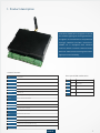
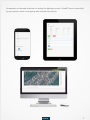
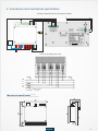
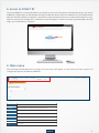
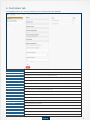
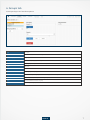
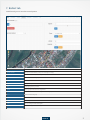
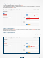
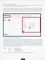
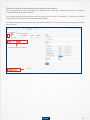
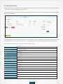
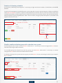
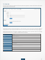
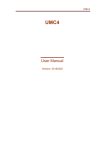
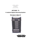
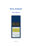
Est. 1988
User Manual
Control Unit
StreetRT
Content
Product description
1
Connection and mechanical specifications
3
Access to Street RT
4
Main menu
4
Controllers tab
5
Groups tab
7
Ballast tab
9
Scheduler tab
12
Astroclock tab
15
Site tab
17
Distribution Panel
Ethernet
Real-time Lighting Control
Autonomous Lighting Control
User Friendly Web Application
StreetRT Web application
Control Unit StreetRT
with GPRS modul
Modulation Unit
PANTER PNT 360
Powerline Communication
1. Product description
Controller STREET RT is designed to control
the outdoor lighting via existing powerlines.
Its signals are transferred to the powerline
through PANTER PNT360 modulator.
STREET RT is equipped with ethernet
interface, which is used for communication
with user. Device construction guarantees a
high operational reliability.
StreetRT content
Item
Description
TST
signals the state of device
ERR
signals error
3V3
signals power-on
LAN
ethernet RJ45 connector
MicroSD
MicroSD slot
12-24V
power suplly 12-24 V DC, polarity doesn`t matter
RS485
serial communication RS485
UART
universal asynchronous receiver/transmitter
ANT
GSM connector female
DSxx
thermal sensor connection
OPi1
pulse output from electricity meter of Panter
OPi2
connector for door sensor
OPi3
manual dimming - Broadcast 100%
OPi4
connector for twilight switch
OPo1
connector for control of solid state relay
OPo2
connector for control of solid state relay
Front panel LED combination
seak.sk
TST
Status
Description
On
On
bootloader
Blink
Off
device in use
Blink
On
bad firmware
Off
On
error in device
1
Screenshots of the web interface for setting the lighting controls. StreetRT can be controlled
by your phone, tablet or computer with internet connection.
seak.sk
2
2. Connection and mechanical specification
Connection of STREET RT with the control portion of PANTER
L
N
SD Card
-
SIM
SSR
~ ~ - +
SSR2
DS
18S20
- +
Connection of PANTER power section
VSTUP
VÝSTUP
PE
N
L1
L2
L3
Fu1 3x63A
Ochranný prvok
max. 63A
Mechanical specification (in mm)
(for PANTER dimensions see Modulator PNT360 datasheet)
42
16
8
8
82
82
14
110
14
100
seak.sk
3
3. Access to STREET RT
To access STREET RT, connect LAN cable to your device and to your access point or PC/laptop. Now you can access
STREET RT configuration via web browser (Chrome, IE, Mozzila, Opera). Fill in the address bar in your web browser
with the device IP address. IP address is provided to device by DHCP and you can check the IP address of your
device in access point configuration. A welcome screen will appear. To enter main menu press FALCON and enter
Login: „op“ and Password: „compact“.
IP ADDRESS
START
4. Main menu
After pressing the FALCON button and login, the main menu will appear. In main menu you have access to all
configuration options available in STREET RT.
Item
Description
Controller
view an summary of basic settings, summary of programed groups
Groups
creating groups and setting the level of dimming for individual groups
Ballast
inclusion and addressing luminaires into groups by ID
Scheduler
establishing the timetable for dimming lights and groups
Astroclock
establishing the timetable for dimming lights and groups depending on location
Site
Location data
seak.sk
4
5. Controllers tab
In controllers tab you can access configuration for communication with PANTER.
Item
Description
New controller address
creates a new configuration
Configured PANTER controllers
list of PANTER devices and their address which is set on PANTER (from 32-63)
Address
Panter`s address
Controller state
see Modulator PNT360 datasheet
Controller version
version of Panter`s firmware
Consumed energy
amount of consumed energy
Consumed energy timestamp
date and time, when was set the origin value of consumed energy
Active phases
set the count of active phases
Modulator temperatures
temperatures of individual phases of modulator
Set number of active phases
set the coun of phases that are active
Meter preload
set the origin value of consumed energy
Broadcast setpoint
set the lighting intensity for all luminaires
Save
saves values that have been set
Delete
deletion of saved values
Group
name of the group, that is assigned to chosen controller
Power
light intensity of luminaires of the group
seak.sk
5
Adding and creating new configuration of modulation unit PANTER PNT360
Adding a new moudlation unit is performed via function New Controller address. According to attached
documentation of modulation unit, we fill address and click Add. Subsequently it is necesarry to confirm settings
with Commit button. After correct configuration, you see OK status and in Configured PANTER controllers tab
you`ll see the number and name of installed PANTER.
1. New controller address
2. Add
3. Commit
4. status OK
Test of connection between modulation unit PANTER PNT360 and STREET RT
Device is testing if connection between modulation unit PANTER PNT360 and STREET RT is correct.
After clicking Broadcast setpoint we can set the level of dimming and send the command with Save button.
If connection between modulation unit and control unit is correct lights will dim on wanted level.
Broadcast setpoint
Save
seak.sk
6
6. Groups tab
In Groups tab you can find these options:
Item
Description
Choose controller
choice of PANTER, which we want to configure
Configured groups
view groups of chosen PANTER
New group address
vytvorenie novej skupiny pre požadovaný PANTER
Description
name of group, if not specified it will be set to Group #X
Save
save values
Delete
delete saved values
Setpoint
set the lighting intensity of group
Test
sends the intensity value to group, so user can see how lights lit at set intensity level
Revert
set the default value (for example: if it was changed by test)
Set
set selected illuminance value for the group
Assigned ballasts
ballasts assigned to group
seak.sk
7
Creating a new group
Before the creation of group it is necessary to chose the ID of control unit which is installed in the switchboard.
We fill individual fields in Groups tab in this order. In the New group address, fill the group ID. After clicking Add
button, group with new address will be added. Afterwards it is necessary to commit changes by clicking
Commit button. After correct configuration we`ll see OK status and number and name of added group will
appear in Controllers tab.
1. Choose controller
2. Number of new group
3. Add
4. Commit
5. status OK
Editing and deleting groups
First we enter name of the group into Description field (for example Main street, Street Nr. 1). Afterwards we
save the name by clicking the Save button. In field Setpoint, we set lighting intensity for group and commit
with button Set. If user want to try level of intensity, he can do it by clicking Test button. If it`s necessary to set
original value it can be done by pressing Revert button.
If we want to delete group we mark it and press Delete button. Afterwards we need to commit changes by
Commit button.
1. Save
2. Nastavenie úrovne stmievania
3. Set
seak.sk
8
7. Ballast tab
In Ballast tab you can see this control options:
Názov položky
Popis
Choose controller
výber požadovaného PANTER, pre ktorý sa budú konfigurovať skupiny
New ballast address
vytvorenie nového balastu (číslo musí byť unikátne)
Delete
deletion of ballast from the group
Add
creates new ballast
Setpoint
lighting intensity of the ballast
Set
set the lighting intensity for ballast
Group
choice of group in which we want to assign ballast
Save
saves values that have been set and assign ballast in to the group
Reset
deletion of ballast from group
Latitude
sets the latitude
Longitude
sets the longitude
Save
saves the settings of latitude and longitude
Reset
cancels the settings of latitude and longitude
seak.sk
9
Adding luminaire to system
Before creation of group it`s necessary to choose number of controller which is installed in the switchbox. Adding
lamp in to the system is realized by filling the ID of lamp in the New ballast address field and proceeding by Add
button. Afterwards it is necessary to commit changes by Commit button. Level of dimming is set in Setpoint field
and commited with Set button. If everything was correct, ID of new lamp will appear in list on the left side of display.
1. Choose controller
4. Nastavenie úrovne stmievania
5. Set
3. Add
5. Nastavenie polohy balastu
2. Number of new ballast
Setting the location of ballast
You can set location of every ballast by setting it`s latitude and longitude and it`s location will be shown on map
through google api. If we set latitude and longitude to every individual ballast, they will be all shown on the map
and after clicking on ballast shown on the map you can see it`s settings. Field “Latitude” is used for setting latitude
of chosen ballast. Field “Longitude” is used for setting longitude of chosen ballast.
seak.sk
10
Adding and reassignment of lamp in the group
In the Group field we fill ID of group a commit by clicking Save.
In case of changing group number for individual lamp we choose it`s ID and change the settings for chosen lamp.
Afterwards we commit with Save button.
1. Number of group
2. Save
Deletion of lamp from group
We choose lamp ID and press Reset (1a). Afterwards it is necessary to commit changes by Commit button. Chosen
lamp will not be assigned to any group.
Deletion of lamp from system
We choose ID of lamp and and press Delete button (1b). Afterwards it`s necessary to commit changes by pressing
Commit button.
1b. Delete
1a. Reset
seak.sk
11
8. Scheduler tab
Item
Description
Choose controller
select the PANTER, that we want to configure
Power
intensity of lighting
Group
group number
Interval
time interval by “Job scheduler”
Enabled
display if the individual task is enabled or disabled
Enable
enable task
Delete
delete task from list
Disable
disable task
You can create several tasks for each groups. Their count is not restricted. Execution of each task is entered in Cron
format. Tools for creation of task are on the right side of the screen.
Item
Description
Group
choose the name of group
Interval
cron format of time when the task have to be carried out
Power
set the lighting intensity
Add
add task to the list
Save
save tasks
Reload
delete ballast from group
seak.sk
12
Creation of time harmonogram
You can create several tasks for each groups. Their count is not restricted. Execution of each task is entered in Cron
format. Tools for creation of task are on the right side of the screen.
After creation of dimming harmonogram it`s necessary to login a choose number of modulation unit PANTER
PNT360. Creation of harmonogram is provided by menu on the right side of screen. We choose group of light,
insert time interval in Cron format and set level of dimming in percent. We send command with filled parameters
by pressing Add button. After correct creation, new group with description of parameters will appear on left side of
screen.
1. Number of controller
2. Create dimming schedule
3. Add
Creating dimming interval in CRON format
Dimming interval can be created for all luminaires by checking the broadcast option in Create dimming schedule,
or for individual group, which can be chosen in the same part of screen. Next step is to set interval, which can be set
in Cron format or by chosing items from lists. There are independent lists for minutes, hours, days in month,
months and days in week. For every list we can choose from four options (every, each, list, range). So it`s possible
that dimming interval will be active every Monday. Another option is that interval will be active every day. Third
option is to set the list of days on which will be the interval active. Last oprion is to set range of days in which will be
current harmonogram active e.g. from Monday to Friday. This options are available for all settings, meaning, for
minutes, hours, day in month, months and day in week.
Examples:
0 21 * * *
51***
*2***
001**
-
every day at 21:00
every day at 1:05 ráno
every minute from 2:00 to 2:59
every first day in month
There are free convertors for converting time to CRON format for dimming harmonogram.
seak.sk
13
Disable, enable and delete group with schedule from system
We choose group by its name and click Disable. Afterwards it`s necessary to commit changes with Save button.
Selected harmonogram will be disabled.
To re-enable group with schedule we mark the group and click Enable. Afterwards it`s necessary to commit
changes with Save button. Selected schedule will be enabled.
For deletion of group from system we choose group and click Delete. To save new settings it necessary to commit it
by Save button.
1. Choose a group
2. Enable, Disable and Delete
3. Save
seak.sk
14
9. Astroclock tab
In Astroclock tab it`s possible to create dimming schedule, like in Scheduler tab. Difference is that in Astroclock tab
is schedule created relatively to sunrise/sunset.
Individual setpoints are relative to sunrise/sunset, where time of unrise/sunset is loaded automaticaly considering
location from Site tab.
Control options are similar to these in Scheduler tab. Difference is that setpoints are not in Cron format, but it`s set
by chosing the Event (sunrise/sunset) and Offset, which represents time interval from chosen event in minutes.
Control options for Astroclock tab, are described in table below.
Item
Description
Choose controller
set Panter, we want to configure
Power
lighting intensity
Group
name of group
Event
sunrise/sunset plus offset
Enabled
displays if task is enabled or disabled
Enable
enable task
Delete
delete task from list
Disable
zakázať vybranú úlohu
Group
chose group for which we want to add tasks
Event
chose sunrise/sunset
Offset
time interval relative to Event
Power
set lighting intensity
Add
add task to list
Save
save task
Reload
remove ballast from group
seak.sk
15
Creation of dimming schedule
For creation of dimming harmonogram it`s necessary to login and choose number of modulation unit PANTER
PNT360.
Creation of harmonogram is provided by menu on the right side of screen. We choose group of light, for which we
chose Event and Offset in minutes. Setpoint is defined by Event and Offset. Event is sunrise or sunset, and its time
is loaded automaticly considering the location and Offset is time interval relative to Event. We send command with
filled parameters by pressing Add button. After correct creation, new group with description of parameters will
appear on lef side of screen.
1. Number of controller
2. Create dimming schedule
3. Add
Disable, enable and delete group with schedule from system
We choose group by its name and click Disable. Afterwards it`s necessary to commit changes with Save button.
Selected harmonogram will be disabled.
To re-enable group with schedule we mark the group and click Enable. Afterwards it`s necessary to commit
changes with Save button. Selected schedule will be enabled.
For deletion of group from system we choose group and click Delete. To save new settings it necessary to commit it
by Save button.
1. Choose a group
2. Enable, Disable and Delete
3. Save
seak.sk
16
10. Site tab
Site tab is used to determine longitude and latitude, where the equipment is located and based on these data is
determined by sunrise and sunset.
Adjusting the position in latitude and longitude, is used to determine sunrise and sunset for AstroClock. When we
choose sunrise or sunset in Event field in Astroclock tab, the time loaded in Site tab will be automaticaly assigned.
Restore point means that, if this option is checked, on power failure and after powerline reboot the controller
sends last command, so it can`t happen that lights will shine during day.
Item
Description
Location
location where equipement is set
Latitude
latitude
Longitude
longitude
Sunrise
time of sunrise
Sunset
time of sunset
Save
save the location data
Settings
settings
Restore ...
restore boradcast and settings of groups at start
Save
save settings
Documentation
documentation
Add document
add document
seak.sk
17
Levočská 109
080 01 Prešov
Slovakia
www.seakenergetics.com
[email protected]
Tel.: +421 (51) 77 15 065