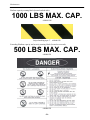
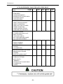
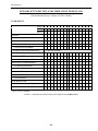
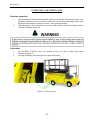
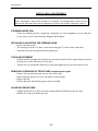
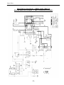
1
E-480SC
OPERATOR AND MAINTENANCE MANUAL
SPARE PARTS LISTS INCLUDED
SERIAL NUMBER : 1038854 & UP
Printed in Canada
One Year Limited Warranty
Effective April 25, 2005, MOTREC, Inc. (MOTREC) hereby warrants to the Original Retail Purchaser (Owner) that any of its
vehicles shall be free from any defect in materials for a period of 90 DAYS while in the possession of such Original Retail
Purchaser. This warranty IS NOT TRANSFERABLE to any subsequent Buyer.
The warranty period is extended to one year or one thousand (1,000) hours, which ever first occurs, on the electric motor,
differential (parts that bathe in oil) and the electronic speed controller. MOTREC makes no warranty or representation with
respect to the internal combustion engine, tires and batteries, since their respective manufacturers cover such parts.
Accessories (light, gage, horn, etc), electrical contacts (switch, solenoid, contactor, relay), diodes & fuses, belts & pulleys,
filters & spark plugs, lubricants, brake linings & shoes, brake drums & discs, seals, seats, trim and other items subject to
wear are not included in this warranty; nor is any item that in MOTREC sole opinion, shows evidence of neglect, misuse,
abuse, collision or alteration.
This warranty shall not apply to normal maintenance requirements as described in the User Manual, and to damages during
shipment. The latter is the carrier's responsibility. No compensation will be allowed for delays.
To initiate warranty coverage on any MOTREC vehicle, the Dealer must complete and return the “Sales/Installation Report”
to MOTREC within 30 days after delivery to the Original Retail Purchaser; or within 90 days after the delivery date to the
Dealer, which ever occurs first. Failure to follow these procedures will result in considering the warranty coverage effective
as of the shipment date from the factory.
The defective vehicle must be returned, at the Owner's expense, to an authorised MOTREC Dealer within 30 days after
failure. The Owner will not be charged for parts and labour required for warranty repairs, which must be performed by an
authorised MOTREC Dealer only. The vehicle will be returned at the owner’s expense. The Warranty Claim Forms must be
completed and returned with the defective part(s) to MOTREC within 30 days after repair was done. No compensation will be
allowed for damages caused by vehicle downtime.
It is the responsibility of the owner of the vehicle to make sure that the driver is properly trained and instructed in the safety
features and operation of the vehicle, including vehicle stability, as required by OSHA and ANSI-B56. Operators shall read,
understand and follow the safety and operating instructions in MOTREC Manual before driving the vehicle. Operators shall
not be permitted to drive the vehicle unless a complete and adequate training has been provided. Driving a vehicle
constitutes a hazard. The driver is responsible for the control of the vehicle while driving and must always evaluate and care
for all peculiar situations that he or she may meet while driving. The driver assumes the inherent hazards related to this
activity. The vehicle is designed for off-road use only. MOTREC disclaims any liability for incidental or consequential
damages, to include, but not be limited to, personal injury or property damage arising from vehicle misuse, lack of
maintenance or any defect in the vehicle.
It is the responsibility of the Owner of the vehicle to make sure that the service technicians are properly trained as required
by OSHA and ANSI-B56. Service technicians shall read, understand and follow instructions in the MOTREC manual before
servicing the vehicle. Only qualified and authorized personnel shall be permitted to maintain, repair, adjust and inspect the
vehicle.
MOTREC prohibits, and disclaims responsibility for, any vehicle modification altering the weight distribution and stability,
increasing the speed or affecting the safety of the vehicle. Such modifications can cause serious personal injury or property
damage for which MOTREC disclaims any responsibility.
For Owners that are located outside North America, the warranty period starts the date of shipment from the factory, and the
defective parts must be returned at the Owner's expense to MOTREC prior to warranty repair.
20/04/2006
Table of contents
IMPORTANT…...IMPORTANT…...IMPORTANT……IMPORTANT
Real and follow safety and operating instructions
TABLE OF CONTENTS
SAFETY
SAFETY WARNINGS FOR OPERATORS
USE OF NOTES, CAUTIONS AND WARNINGS
GENERAL OPERATING RULES, SAFETY AND LIMITATIONS
PERSONNEL QUALIFICATIONS
SAFETY FEATURES
MAINTENACE LOCK
INTRODUCTION
DESCRIPTION
SPECIFICTIONS
OPERATION
PRELIMINARY INSTALLATIONS
SCISSOR LIFT OPERATION PROCEDURE
TO MOVE VEHICLE
HYDRAULIC OIL FILL-UP PROCEDURE
OPERATING INSTRUCTIONS
MAINTENANCE
SAFETY WARNINGS FOR SERVICE TECHNICIANS
DECALS AND LABELS
PERIODIC MAINTENANCE CHECKLIST
SCISSOR PERIODIC MAINTENANCE CHECKLIST
SCISSOR LIFT INSPECTION AND LUBRICATION WEEKLY LOG
INSPECTION AND LUBRICATION
ACCELERATOR
BELT INSTALLATION AND TENSIONING
HYDRAULIC BRAKES
FRONT AXLE AND STEERING
BATTERY MAINTENANCE
BATTERY CHARGER
ELECTRICAL TROUBLESHOOTING
SCISSOR TROUBLESHOOTING
HYDRAULIC SYSTEM
CURTIS PMC MOTOR CONTROLLER
OVERVIEW
WIRING : STANDARD CONFIGURATION
MAINTENANCE AND ADJUSTMENT
SPARE PARTS
BODY
-3-
5
6
7
7
8
8
9
10
11
12
13
14
15
16
16
17
19
20
22
28
29
30
31
32
33
34
35
36
38
39
42
45
48
50
52
55
58
59
Table of contents
DOWN VALVE ASSEMBY
CAB
FORD F-150 DIFFERENTIAL
BRAKE CONTROLS
FRONT ASSEMBLY
MOTOR AND DRIVE
REAR SUSPENSION AND BRAKE
ELECTRICAL DIAGRAM – SERIES MAIN CIRCUIT
ELECTRICAL DIAGRAM – CHARGER AND BATTERY
ACCESSORIES – NO DC/DC CONVERTER
ACCESSORIES – DC-DC CONVERTER
OPTIONS
SCISSOR LIFT - ELECTRICAL CIRCUIT
BATTERY CONFIGURATIONS - 48V
BUILT-IN / PORTABLE 25A CHARGER
MOTREC ILLUSTRATED ACCESSORIES
BATTERY DISCHARGE INDICATOR (HOBBS)
ADDENDUM
CURTIS FOOT PEDAL
-4-
61
63
64
67
68
70
71
72
73
74
75
76
77
79
82
83
85
86
87
Safety
SAFETY
-5-
Safety
SAFETY WARNINGS FOR OPERATORS
•
FAILURE TO OBEY THE FOLLOWING SAFETY RULES MAIN RESULT IN SEVERE INJURY.
•
It is the responsibility of the owner of this vehicle to train operators to ensure that they understand the operating
characteristics of this vehicle, including training in vehicle stability, and obey the following safety rules and
guidelines. Owner shall comply with OSHA and ASME/ANSI B56.8 & B56.9 regulations for vehicle use,
safety rules, operator training and certification. Do not drive this vehicle unless you are a qualified operator.
•
Do not drive this vehicle under the influence of drugs or alcohol.
•
Do not drive this vehicle on public roads and highways. This vehicle is designed to be driven in buildings.
•
The electrical system of this vehicle will make sparks which can ignite inflammable materials. Never use the
vehicle in hazardous areas where there are inflammable materials, explosive dust or fumes in the air.
•
Have your vehicle inspected regularly by trained personnel, and cease operation if a malfunction occurs.
•
Do not open battery compartment to prevent battery explosion, acid splashing, severe damage to eyes or skin.
•
Do not open motor compartment. Keep clear from moving, rotating(wheels, sheaves, etc) or lifting parts.
•
Never carry more passengers than number allowed for this vehicle. Wait until all occupants are seated and
holding on before moving. Always keep all body parts inside vehicle. Keep both hands on steering wheel.
•
Do not exceed the vehicle cargo load capacity and gross trailing weight capacity, rated for flat hard even surface.
Different operating conditions such as loose terrain or ramps reduce vehicle capacity.
•
Avoid loose, unbalanced or top-heavy loads to keep a good stability and prevent overturn. Do not load cargo that
can fall off the vehicle. Do not carry cargo that is longer, wider or higher than this vehicle.
•
Always depress slowly the accelerator for smooth acceleration. Avoid stunt driving or horseplay.
•
Avoid sharp turns, always slow down before turning, to prevent vehicle overturn or trailer jack knife. Vehicle is
more sensitive to overturn and jack knife when traveling on inclines or when carrying a heavy load.
•
Always drive straight up and down the face of an incline, never across the face, to prevent overturn and trailer
jack knife. Drive slower and start applying brakes sooner on inclines to adjust for longer stopping distance.
•
Use extra care and drive slowly in reverse, in congested areas or on wet or slippery ground.
•
Keep to the right under normal conditions. Maintain a safe distance from all objects.
•
Slow down and sound the horn when approaching a corner or other blind intersections.
•
Before leaving the vehicle, park on a level ground flat surface, turn off all switches, set the forward/reverse
switch to neutral, set the parking brake, remove the key. Do not park the vehicle on an incline.
•
Before battery charging, park the vehicle in a well ventilated area set for. Do not operate it when charging. To
interrupt a charging cycle, disconnect the AC plug; disconnecting the DC plug or a battery terminal, or operating
the vehicle, could damage the charger and produce a spark, battery explosion and acid splashing.
•
Use another driver to steer this vehicle while it is towed. Be sure the driver uses brakes when you slow or stop
the towing vehicle. Do not exceed 5 MPH or carry any passenger while towing this vehicle.
-6-
Safety
USE OF NOTES, CAUTIONS AND WARNINGS
NOTE – additional information to further explain instructions.
CAUTION – Failure to follow instruction could cause damage to equipment.
WARNING – Failure to follow instruction could cause death, personal injury and property damage.
DANGER – Failure to follow instruction will cause death, personal injury and property damage.
GENERAL OPERATING RULES, SAFETY AND LIMITATIONS
•
•
•
•
•
•
•
•
•
Inspect machine before using. Do not use machine if it is not working properly in any way.
Check job site for unsafe working conditions.
Do not operate on uneven or soft terrain.
Do not raise platform if machine is on an incline.
Never carry people and/or cargo on platform while moving.
Use machine only for purposes for which it was designed.
Do not raise platform if stabilizers are not fully extended and lock.
Do not exceed the load capacity of platform (1000 lbs) and the load capacity of extended deck (500 lbs)
An operator of any type of work platform is subject to certain hazards that cannot be protected by
mechanical means. It is therefore essential that operators be competent, careful, physically and
mentally fit and thoroughly trained in safe operation of this machine.
-7-
Safety
PERSONNEL QUALIFICATIONS
* Operation of E-480SC shall be restricted to certified personnel as required by OSHA.
* Maintenance of E-480SC shall be restricted to qualified trained personnel as required by OSHA.
* Before operation or maintenance, personnel shall read and thoroughly understand this manual. If a
proposed operator or maintenance man fails to understand any segment of this manual, his Supervisor
can clarify the misunderstanding through written correspondence or phone call to:
MOTREC inc, 200 Indusrial Boul. South, Bromptonville (Quebec) Canada, J0B 1H0
Phone: (819) 846-2010 ext: 226
Fax: (819) 846-3050
E-mail: [email protected]
Web site: www.motrec.com
SAFETY FEATURES
1.
Platform won’t move up if stabilizers are not fully extended.
Stabilizers won’t disengage if platform is not fully down.
Vehicle won’t travel if stabilizers are not fully retracted.
2.
Emergency Stop: The emergency stop is located on the control console. Depress red knob as
indicated and all functions of machine will be de-energized. Pull the knob to reactivate
circuits (Figure 1).
3.
Emergency Down
The emergency down control is located on the left side. Pull handle to allow platform to
descend back to the stowed position (Figure 2).
Figure 1. Control Console Emergency Stop
Figure 2. Emergency Down Handle
-8-
Safety
MAINTENACE LOCK
1.
Remove load from platform.
2.
Raise platform as high necessary to engage maintenance lock.
3.
Maintenance lock is located at the rear of the unit between the inside beam assemblies.
With machine raised part way, lift maintenance locks and lower machine so that pivot pins are
resting on maintenance lock (Figure 3).
Figure 3. Positioning Maintenance Lock
-9-
Introduction
INTRODUCTION
- 10 -
Introduction
DESCRIPTION
Motrec E-480SC is electrically driven, hydraulically operated units. The platform is raised and lowered
by a scissors mechanism. Motrec E-480SC platform is raised by a hydraulic cylinder, which is
controlled from the control console on the platform. Emergency lowering and auxiliary lift controls
located at the base of the machine.
Figure 4. Motrec E-480SC
- 11 -
Introduction
SPECIFICTIONS
Through our constant efforts to improve our products, specifications may change without notice.
E-480SC Mobile Lift
The E-480SC is engineered for large industrial plants that require rapid response over long distance.
The E-480SC is ideal for warehouse, airport and in-plant uses. The E-480SC is the only vehicle of its
kind and includes:
•
•
•
•
•
•
•
•
•
•
•
•
•
•
Descent alarm and flashing light.
48 volt drive controls and accessories.
24 volt hydraulic controls and a 4HP pump.
Eight 6V/220AH deep cycle batteries.
Roll-out battery tray.
48V/25A Lestronic II charger.
Automotive differential.
Curtis-PMC electronic speed control
Curtis 802 battery discharge indicator.
48V headlight, tail/brake lights and horn.
Hydraulic disc brakes on all four wheels.
Front and rear leaf spring suspension.
5.70 x 8 L.R.D. tires
1000 lbs platform capacity (500 lbs extended platform capacity).
The E-480SC carries two people up to 8 MPH for faster response to maintenance or emergency sites. It
is fully self-contained and able to move over railroad crossings and rough terrain. This is due to its use
of large tires and automotive leaf springs in the front and rear. Motrec even offers the availability of
special boxes on the platform for airport and warehouse needs.
- 12 -
OPERATION
OPERATION
- 13 -
OPERATION
Description
PRELIMINARY INSTALLATIONS
1.
Remove all packing materials and inspect for possible damage during shipment. Report any
damage immediately to the person delivering the equipment.
2.
If side railings are not installed, install side railings on four sides of the platform. Pin front
and rear rails to the sides with clevis pin provided. Check that platform extension slides
freely, and gate swings freely.
NOTE
To install extending platform, refer to the extending platform illustration in this manual
3.
Make sure carrying capacity and warning decals provided state correct capacity for your
machine, and are installed to platform as illustrated.
Figure 5. Platform Railings and Warning Decal.
- 14 -
OPERATION
4.
5.
6.
7.
8.
If not assembled before shipment, connect cable to control console provided and install
console on platform railing. Pull emergency stop button if it has been depressed (Figure 6).
If wheels have not been installed, install them.
Pull emergency stop button on lower control station if it has been depressed (Figure 6).
Check oil level in hydraulic reservoir (see sight glass). See next page fill-up procedure.
Inspect machine for hydraulic oil leaks. Do not use the machine until leaks are serviced.
SCISSOR LIFT OPERATION PROCEDURE
9.
10.
11.
Turn key switch at “lift” position.
Fully extend stabilizers using toggle switch at “stab” position at lower control station.
Make sure legs will stand on even surface.
Move up platform using toggle switch at “up” position at lower control station or using
toggle switch “up” position* (upper control station). To stop platform movement,
release the toggle.
*If you have 2-speed option: Lower station default is “up fast” while upper station default is
“upslow”, Simply press “upslow” switch and “fast” button at the same time to get “upfast”
function.
Figure 6. Controls
12.
13.
MAKE SURE MAINTENANCE LOCK IS SECURELY POSITIONED ON ITS
SUPPORT AND WON’T DISTURB BEAN MOVEMENT.
Use toggle switch at “down” position to move platform downward (any station). To
stop platform movement, release the toggle.
- 15 -
OPERATION
TO MOVE VEHICLE
14.
To unlock stabilizers, activate stab switch and pull unlock lever. Keep pulling lever while
activating unstab switch to retract stabilizers.
Figure 7. Unlock main lever
15.
When stabilizers are fully retracted, sit down, turn key switch at F/R position to move
vehicle, set F/R switch for direction.
NOTE: Stabilizers must be fully extended to operate the platform; or fully retract to move
vehicle forward/reverse. If the platform is partly raised, stabilizers cannot be activated.
HYDRAULIC OIL FILL-UP PROCEDURE
•
Lower platform so that maintenance lock is resting on pivot pin.
•
•
•
Remove filler cap and check fluid reservoir. Fill to proper level using AWE32 hydraulic oil.
Replace filler cap. Raise platform slightly and retract maintenance lock.
Inspect hydraulic system for leaks. Check oil leakage at leg bottom hole.
- 16 -
OPERATION
OPERATING INSTRUCTIONS
It is the responsibility of the owner of this vehicle to ensure that the operator understands the
operating characteristics of this vehicle, and obeys the safety instructions (ANSI B56).
Do not drive this vehicle unless you are a qualified operator.
BEFORE USING VEHICLE
Before turning on key switch: set to neutral, check for any visible damage, check brake pedal.
BATTERIES
Never open the battery compartment unless you have received proper training for battery maintenance.
Batteries emit explosive hydrogen gas that can be ignited by a spark or loose terminal. Battery acid
causes severe damage to eyes or skin. Flush the contaminated area immediately with water.
BATTERY CHARGER
Park the vehicle in a well ventilated area for battery charging. Most battery chargers come with an
electronic control that starts when the charger is plugged and stop when the battery is fully charged. To
interrupt the charging cycle, disconnect the AC-plug, do not disconnect the DC plug.
BATTERY DISCHARGE INDICATOR
The green light moves from right to left as batteries are being discharged. When the green light is at the
last position on the left the batteries must be recharged. A flashing light warns the operator that further
discharge will damage batteries. See HOBBS indicator instructions
KEYSWITCH/LIGHTS
Three positions with off at center. Depress brake pedal and turn the key switch clockwise for F/R
position and turn headlight on. Turn key switch clockwise to operate the platform. Always turn off all
switches, set the F/R selector to neutral, set the parking brake, and remove the key before leaving the
vehicle.
HORN
Depress the horn button on the steering column or handle bar.
F/R SWITCH
Three positions with neutral at center. Depress the front part of the rocker switch for forward direction.
Depress the rear part of the rocker switch for reverse direction. Always set switch to neutral, turn off all
switches, set the parking brake, and remove the key before leaving the vehicle.
ACCELERATOR PEDAL
It is designed for right foot operation only, and controls the speed of the vehicle.
FOOT BRAKE PEDAL
It is designed for right foot operation only. The brake force is proportional to the pressure on the pedal.
PARKING BRAKE
Pull handbrake lever to apply. Never park the vehicle on an incline. Always turn off all switches, set
the F/R selector to neutral, set the parking brake, and remove the key before leaving the vehicle.
- 17 -
OPERATION
CONTROLS IDENTIFICATION – PLATFORM
EMERGENCY PUSH BUTTON SWITCH
Pull the emergency stop button on the lower control station to turn ON platform.
This switch cuts all power to the platform when it is pushed.
Pull the emergency stop button on the upper control box for UP/DOWN operation.
STABILIZERS
The stabilizer control switch is located on lower control station.
FOLD DOWN GUARDS
Before lifting the platform, raise the guards and lock with pins at each corner.
EXTENDING PLATFORM
Remove the lock pin, push the platform forward and lock with pin. (Figure 8)
Figure 8. Extended platform
UP/DOWN
Stabilizers must be fully extended. UP/DOWN switches are located on the upper control box and the
lower control station. Manual down control handle is located on the left side.
- 18 -
Maintenance
MAINTENANCE
- 19 -
Maintenance
SAFETY WARNINGS FOR SERVICE TECHNICIANS
FAILURE TO OBEY THE FOLLOWING SAFETY RULES MAIN RESULT IN SEVERE INJURY.
Owner shall comply with OSHA and ASME/ANSI B56.8 & B56.9 regulations for vehicle maintenance.
Only qualified and authorized personnel shall be permitted to maintain, repair, adjust and inspect
carriers, vehicles, tractors, and batteries.
Before any maintenance work, park the vehicle on flat level surface, turn off all switches, remove key,
lift wheels off the ground and secure with jack stands of adequate capacity. Don’t connect charger.
Keep clear from moving parts such as tires, sheaves and motor.
Follow the maintenance instructions applicable to the type of repair, maintenance, or service.
Always wear a face shield and gloves when working around batteries.
Before opening the battery compartment, disconnect the charger, turn off all switches and remove the
key. Batteries emit highly explosive gases which greatly increase when charging; do not disturb
connections or produce sparks around batteries to avoid a battery explosion and acid splashing. Battery
acid causes severe damage to eyes or skin. Flush contaminated area immediately with water.
Use insulated tools to avoid sparks that can cause battery explosion and acid splashing.
Use two counteracting tools, double-wrench technique, when disconnecting or tightening terminals on
the battery and the speed controller to avoid cracking the terminal or battery post welds.
Before cleaning or replacing a battery, charger, speed controller, contactor, relay, diode, or any other
component in the power circuit, always disconnect the charger, turn off all switches, remove the key,
wear a face shield and gloves, identify battery polarity and disconnect battery leads, discharge the
capacitor in the controller with a 10 ohms, 25 W resistor for a few seconds across B+ and B-.
After cleaning, the power must not be reapplied until terminal areas are thoroughly dry.
On EE-Rated vehicles make sure that the control box is sealed, the static strap makes good contact with
the ground, the motor is sealed by bands, the cable protectors are properly installed.
Keep cables and wires clear from mechanical and rubbing action. Make sure that cable insulation is
free from cutting or visible damage. Make sure that EE-Rated cable protectors are properly installed.
Before replacing a fuse or circuit breaker, identify the cause of failure and repair.
Programmable controllers must be programmed using the parameter settings in this service manual,
before connecting the motor, to avoid sudden vehicle movement and accident.
- 20 -
Maintenance
Do not try to increase motor speed by changing parameter settings in the speed controller; it can cause
accident and severe damage to the motor.
SEPEX speed controls are protected by a diode in the power circuit to filter inductive loads in the event
of a sudden power interrupt. Some speed controllers require a diode to filter inductive loads on the KSI
input. Removing the diodes will cause the speed control failure.
Before resuming maintenance operations, inspect safety warnings stickers and replace any if damage is
found and part of the text can’t be read.
- 21 -
Maintenance
DECALS AND LABELS
! CAUTION !
The images included in this section depict the decals/markings installed on the vehicle. It is of
the utmost importance that theses decals/markings remain unaltered and readable. Else, the
sticker or the part baring the marking has to be replaced.
Dashboard security warning label:
#5100000002
General security warning label:
#5100000001
#4800012O
#4800012D
- 22 -
Maintenance
Respectively, forward/reverse selector and light switch marking:
Key switch marking:
LIFT F/R
#4800012S
Scissor security warning labels (located on both side):
KEEP CLEAR
#4800012L
Striped marking tape 4”
#4800012W
Stabilizers security warning label (Each faces, sides and rear):
Striped marking tape 3” # 30102
- 23 -
Maintenance
Platform capacity warning labels (located on both side):
1000 LBS MAX. CAP.
#4800012M
Striped marking tape 4”
#4800012W
Extending Platform capacity and security warning labels (located on rear end):
500 LBS MAX. CAP.
#4800012N
#4800012X
- 24 -
Maintenance
Security warning label on platform control box:
#4800012E (located on the top of box)
UP DOWN
STOP
FAST
#4800012Q
#4800012U
#4800012Z (Optional 2 speed up)
Maintenance Lock security warning label (Located at the rear end):
#4800012G
Lower control station labels:
STAB
UNSTAB
UP
DOWN
#4800012R
#4800012T
- 25 -
Maintenance
Battery security warning labels:
#4800012H (Located on battery connector side).
4800012K (Located on top of battery tray, connector side).
#4800012J (Located near the battery connector).
- 26 -
Maintenance
Lower Railings security warming labels:
#4800012F (Located on left side, be on lower control station).
#4800012A (Located on left side, beside emergency down handle).
UNLOCK
#4800012V (Located on left side, beside unlock main lever).
#4800012P (Located on right side, in middle).
- 27 -
Maintenance
PERIODIC MAINTENANCE CHECKLIST
! WARNING !
Maintenance operations must be made by properly trained service technicians.
− Keep clear from moving parts such as tires, sheaves and motor.
− Check for all EE protections, when applicable, and keep cables and wires clear from mechanical and rubbing action
− Batteries contain sulphur acid that can cause severe burns on skin or eyes.
− When working around batteries, wear acid proof protective equipment: face shield and gloves.
− Use electrically insulated tools to avoid sparks that can cause battery explosion.
− Before any maintenance work, park the vehicle on a flat level surface, turn off all switches, remove the key, lift the wheels off the
ground and secure with jack stands of adequate capacity, identify and disconnect battery leads. Don’t connect the charger.
PERIOD DAY
CHECK/PERFORM
HOURS
MECHANICAL DAMAGE, OIL LEAKS
X
REVERSE ALARM, DEADMAN SWITCH
X
STATIC STRAP, min 2” contact with ground
X
TIRE PRESSURE, pressure rating on tire
CHECK/FILL BATTERIES, add distilled water to cover
plates. Fill to recommended level after batteries have
been fully charged.
WARNING DECALS & MARKINGS
EE-Rated CABLE PROTECTORS, SEALED MOTOR,
SEALED CONTROL BOX.
MASTER CYLINDER FLUID (DOT 3)
BRAKE PEDAL TRAVEL
2” (50 mm) maximum travel
STEERING FOR PLAY
PARKING BRAKE LEVER
requires 10 lbs. (5 kg) force to apply
BELTS AND PULLEYS
-10 lbs (5kg). force for 1/8” (3mm) deflexion;
-pulleys alignment, see procedure.
CLEAN/TIGHTEN WIRE TERMINALS
WASH BATTERY TOP WITH WATER
MOTOR BRUSHES FOR WEAR
-brushes must exceed holders
ACCELERATOR ADJUSTMENT
-1/8” (3 mm) travel to activate micro-switch;
-0 to 50 ohms when micro-switch activated;
-4500 to 5500 ohms with pedal down.
HYDR. BRAKE LINES FOR LEAK
STEERING ASSEMBLY, as instructed
BRAKE MECHANICAL LINKAGES
for wear & play
BRAKE LININGS FOR WEAR
1/16” (1.5 mm) minimum lining thickness.
LUBRICATE brake pedal pivots, steering column, ball
joints and kingpins.
OIL (SAE 30) LEVEL IN DIFFERENTIAL
Before adding oil, check oil seals for leaks.
FRONT WHEEL BEARINGS PLAY
TIGHTEN NUTS/BOLTS, electric terminals; drive;
steering; brakes; suspension; body.
WEEK
20
MONTH
50
QUART.
200
YEAR
1000
2 YEARS
2000
X
X
X
X
X
X
X
X
X
X
X
X
X
X
X
X
X
X
X
X
X
REPLACE DIFFERENTIAL OIL(SAE 30)
CLEAN AND RE-PACK FRONT HUBS
SERVICE DIFFERENTIAL, replace the three oil seals,
wheel bearings, oil (SAE 30)
X
X
X
- 28 -
Maintenance
SCISSOR PERIODIC MAINTENANCE CHECKLIST
PERIOD
HOURS
CHECK
MECHANICAL DAMAGE
-STABILIZERS
-SCISSOR WELDMENTS
-SCISSOR PIVOTS & SNAP RINGS
-PLATFORM GUARDS
-EXTENDING DECK
DAY
WEEK
20
MONTH QUART.
50
100
YEAR
1000
X
ELECTRIC DAMAGE
-CABLE THROUGH SCISSOR
-CABLE TO UPPER BOX
-CABLE ON LIFTING CYLINDER
-UPPER CONTROL BOX
-LOWER CONTROL STATION
-STABILIZER LIMIT SWITCHES
X
HYDRAULICS SYSTEM
-CYLINDER AND DOWN VALVE
BODY FOR LEAKS
-FLUID LEVEL, AWE 32
-OIL FILTER PRESSURE GAUGE
-OIL FILTER REPLACEMENT
X
SAFETY DECALS
-CHECK IF MISSING
-CHECK IF LEGIBLE
X
X
LUBRICATE
-SCISSOR
-2 CYLINDER PINS
X
PUMP MOTOR BRUSHES FOR WEAR
-BRUSHES MUST EXCEED
HOLDERS
-BLOW OUT CARBON DUST
X
CHECK / TIGHTEN
X
-HYDRAULIC FITTINGS
-NUTS / BOLTS**
-TERMINALS
-SCISSOR PIVOTS & SNAP RINGS
-CYLINDER PINS
-GUARDS
TABLE 10. SCISSOR LIFT INSPECTION AND LUBRICATION SCHEDULE
- 29 -
Maintenance
SCISSOR LIFT INSPECTION AND LUBRICATION WEEKLY LOG
Check and Initial Every 15 Hours of USE or Weekly
COMPONENT
MONTH
DAY
INITIAL
BATTERY
1. Clean Battery
2. Coat Terminals
HYDRAULIC SYSTEM
1. Check Fluid Level AWE32
2. Inspect Commutator and Brushes *
Date Last Checked ________________________________
3. Check Fittings
SCISSOR SYSTEM
1. Check for Damage
DRIVE AND LIFT MECHANISMS
1. Oil Steering Pivot Points
2. Oil Brake Pivot Points
3. Check All Fasteners
MAIN FRAME
1. Check Structure
CONTROL SYSTEM
1. Chack Terminals and Plugs
2. Check Cords
*Check every 6 months
TABLE 11. SCISSOR LIFT INSPECTION AND LUBRICATION WEEKL LOG.
- 30 -
Maintenance
INSPECTION AND LUBRICATION
Structure Inspection
1Check machine for bent structural members. (Beams, main frame, platform, pivot pins, etc.).
Machines which have been overloaded could have bent members and fatigued pivot pins.
Replace all bent members and pins to insure a safe operation machine.
2Check bushings in scissor beams for or cracked welds. Replace beams if bushing welds are
cracked or bushings elongated.
Lubrication
1The MOTREC E-480SC scissor lift contains several pivot pins or rollers that require
lubrication (Figure 9).
2Steering rod linkage pivot and joint also require lubrication.
Figure 9. Lubricate pivots.
- 31 -
Maintenance
ACCELERATOR
GEAR
− Remove the cover.
− Backlash between gears must be reduced to a minimum by sliding holder; use locktite 262
to lock the three screws.
− When the plastic gear is fully depressed a small backlash must remain between the gears.
− When the plastic gear is released its rear portion must not exceed the pedal case.
MICRO-SWITCH
The micro-switch must deactivate the on/off solenoid when the accelerator is released; turn the
adjusting screw (shown on figure below) to adjust the micro-switch height.
POT
− Remove the terminals 2 and 3 on PMC to measure resistance signal.
− When the micro-switch is activated the signal must be less than 50 ohms. When the front
portion of the pedal is fully depressed the signal must be more than 4600 ohms.
− To modify the resistance, turn the adjusting screw to change the micro-switch height (see
figure below).
Proceed with the same verifications after the accelerator cover is on and then connect terminals 2 and 3.
- 32 -
Maintenance
BELT INSTALLATION AND TENSIONING
INSTALLATION
Adjust the sprockets using a straight edge. Slide up the edge on the larger pulley until it contacts the
smaller pulley. Properly adjusted pulleys will provide three points of contact. Properly aligned pulleys
will provide four points of contact. Tighten setscrews and recheck alignment.
TENSIONING
Check the force F required to provide a deflection of 1/8 in. If the measured force is less than 15 lbs
then lengthen centre distance C.
- 33 -
Maintenance
HYDRAULIC BRAKES
DRUM BRAKES
Remove brake drums and check linings wear; the linings should have a thickness exceeding 1/16" (1.5
mm). Turn the brake adjustment to reduce the clearance between lining and drum but avoid contact or
drag when the wheels are turned and the pedal is released.
DISC BRAKES
Check pad linings for excessive wear; the linings should have a thickness exceeding 1/16" (1.5 mm).
Disc brakes are self-adjusting.
BRAKE PEDAL
If the brake pedal becomes soft or spongy, air may have entered the hydraulic system and the brake
system has to be bled:
1. fill the master cylinder with brake fluid (DOT-3);
2. bleed front callipers one at a time by having someone applying a steady pressure on the brake
pedal, and close the bleeder before allowing the brake pedal to return to up position;
3. fill the master cylinder with brake fluid (DOT-3);
4. bleed rear wheel brakes one at a time, following the same procedure;
5. fill the master cylinder with brake fluid (DOT-3);
6. clean every fitting and line, remove traces of oil;
7. apply a continuous pressure on the brake pedal for about five minutes ;
8. Finally, inspect brake lines and fittings for leaks ;
- 34 -
Maintenance
FRONT AXLE AND STEERING
! CAUTION !
Before maintenance, turn off all switches, set to neutral, set parking brake, remove the key,
and raise the front end of the vehicle supporting it with two jack stands of adequate capacity
STEERING INSPECTION
− Check tire inflation pressure, suspension components, tie rods straightness, tie rod ends play
(wear), play (wear) in wheel bearings, kingpins and bushings.
REPLACING & ADJUSTING THE STEERING GEAR
− Remove the pitman arm;
− The steering box makes 6.5 turns, center the steering gear (3.25 turns from either side);
− Align the front wheel straight. Install the pitman arm.
TOE-IN ADJUSTEMENT
− With the wheels in straight forward direction, measure the inside (left to right) distance between
the front tires, at the front and rear of the tires;
− Turn the rear tie rod until the distances are equal and tighten the two lock nuts on the tie rod.
REMOVING & GREASING OF FRONT HUBS, required once-a-year
− Remove dust cap and cutter pin, unscrew nut, remove hub;
− Inspect bearings and races for wear and replace worn bearings;
− Replace the seal;
− Pack the hub with wheel bearing grease and re-assemble.
ADJUSTING FRONT HUBS
− Tighten spindle nut to 30 ft-lb to seat the bearing and back off the nut to the next slot;
− Install a new cutter pin and the dust cap.
- 35 -
Maintenance
BATTERY MAINTENANCE
−
−
−
−
−
−
−
−
−
−
! WARNING !
It is the responsibility of the owner of this vehicle to ensure that the service technicians are
properly trained, read and obey the safety rules and guidelines in this manual (ANSI B56).
Maintenance operations must be made by properly trained service technicians only.
Before any maintenance work, park the vehicle on a flat level surface, turn off all the
switches, set to neutral, remove the key, lift the wheels off the ground and secure with jack
stands of adequate capacity.
Keep charger disconnected while doing any maintenance work.
Always wear a face shield and scarf when working around batteries.
Battery emits highly explosive gases; do not produce sparks to avoid battery explosion and
acid splashing. Battery acid causes severe damage to eyes or skin. Flush contaminated area
immediately with water.
Use insulated tools to avoid sparks that can cause battery explosion and acid splashing.
Use two counteracting tools, double-wrench technique, when disconnecting or tightening
battery posts.
Before cleaning or replacing a battery, discharge the capacitor in the controller with a 10
ohms, 25 W resistor for a few seconds across B+ and B-, identify battery polarity and
disconnect battery leads.
After cleaning, the power must not be reapplied until terminal areas are thoroughly dry.
BATTERY LEADS AND CONNECTORS
Check for loose connections, damaged cables, acid spill, loose terminal posts, quarterly.
BATTERY POST CORROSION
If corrosion is present on battery posts, remove the cable connectors, use a wire brush to remove
particles, and then clean them with a cloth that has been moistened with ammonia.
ELECTROLYTE LEVEL
Does not apply to sealed battery.
− Disconnect battery connectors on roll-out or lift-out installations.
− Make sure the battery roll-out tray is provided with stops before rolling out.
− Fill with distilled water.
− Daily charged batteries normally require watering once a week. Under watering leads to a
shortened battery life. Over watering leads to battery corrosion. Be careful not to overfill any cell to
avoid electrolyte to be forced out while charging.
− Fill each cell to plate level with distillated or de-ionized water, before battery charging. When the
battery is charged, the fluid expands and can seep out if overfilled. Refill each cell after full charge,
when the fluid has expanded to its maximum level.
− Reinstall battery caps before charging.
- 36 -
Maintenance
BATTERY MOUNTING
A loose battery increases damaging effects of vibrations and is more prone to short out.
BATTERY DISCHARGE LIMIT
Discharging below a 20% state of charge cuts down the battery life and the number of cycles available.
At 20% state of charge, specific gravity of 6V battery should be 1180; and 1220 for industrial battery.
CHARGING AREA
− Always charge battery in a well ventilated area set for and approved for charging.
− Never leave a charger connected for more than 20 hours.
FREQUENCY OF CHARGE
− When a battery is discharged to its 20% state of charge, it is best to charge immediately.
− Batteries require a low current equalization charge (min 4 hours) at least every week, to equalize
battery cells, improve battery performance and life in number of cycles.
− Never leave a charger connected for more than 20 hours.
STORAGE
− Keep the battery from getting cold, it would loose its capacity.
− Let the battery warm up before charging.
− Charge batteries in “stored” vehicles every month.
DEFECTIVE BATTERY
Check specific gravity of each cell; if a cell is shorted, voltage drop may occur only when there is
current.
- 37 -
Maintenance
BATTERY CHARGER
! WARNING !
Always unplug the AC and DC electrical cords before attempting any repairs to the charger.
CHARGER DOES NOT TURN ON:
− Dc cord of portable chargers must be disconnected from batteries after every charge to restart;
− Check dc fuse links;
− Check battery voltage at the battery connector;
− Check ac outlet and cordset;
− Replace electronic control ;
RELAY CLOSES AND TRANSFORMER HUMS BUT AMMETER DOES NOT REGISTER:
− Check dc fuse links;
− Check the continuity of the dc output cord, ammeter, diodes and all connections in the dc
circuit;
− Check diodes;
− Check capacitor(rapidely increasing resistance);
SINGLE CHARGER FUSE BLOWS:
− Disconnect and check diodes;
BOTH FUSE LINKS BLOW:
− Check the battery pack and battery connector polarity;
− Disconnect and check diodes.
CHARGER OUTPUT IS LOW:
− Disconnect and check diodes;
− Can be caused by a transformer failure.
AMMETER READS 30 AMPS FOR MORE THAN 30 MINUTES:
− Check the battery pack;
CHARGER DOES NOT TURN OFF:
− Check specific gravity in each battery cell;
− As much as 16 hours may be required to properly charge heavely discharged new or cold
batteries;
− Replace electronic control.
AC LINE FUSE OR CIRCUIT BREAKER BLOWS:
− Check ac cordset;
− Check ac line fuse rating;
− Replace electronic control;
− Can be caused by a transformer failure.
- 38 -
Maintenance
ELECTRICAL TROUBLESHOOTING
! WARNING !
Maintenance work must be performed by trained service technicians only.
It is the responsibility of the owner of this vehicle to ensure that the services technicians are properly
trained, understand and obey the safety rules and guidelines (ANSI B56).
All service technicians must read and understand the maintenance warning section in this manual.
! WARNING !
Before any maintenance work, park the vehicle on a flat level surface, turn off all switches, remove the
key, lift the wheels off the ground, secure with jack stands of adequate capacity, disconnect charger.
Always wear safety glasses.
Batteries emit highly explosive gases that can be ignited by a spark. Before disconnecting a high
current terminal, turn off all switches, disconnect battery charger, disconnect batteries.
Keep clear from moving parts such as tires, sheaves and motor.
PMC SELF DIAGNOSTIC
If your PMC comes with a status led, use the flashing code to help troubleshooting.
BATTERY VOLTAGE
Make sure batteries are securely connected. Measure voltage between + and - terminals. We will call
this value B+ or full battery voltage.
ACCESSORIES NOT WORKING
− Check the fuses on the batteries and the DC/DC converter.
− Check voltage across + and – terminals on the battery gage; if not B+, check wiring.
− Turn the key switch ON, check voltage between output terminal on the key switch and the terminal on the battery gage; if not B+, replace the key switch.
− Check voltage across DC/DC converter output terminals; if not 12-Volt, replace the converter.
− Depress the accessory switch, check voltage across accessory terminals. If not 12-Volt, replace the
switch. If 12-Volt, replace the accessory.
FORWARD ONLY
On a SEPEX motor control, check the reverse signal input on the controller.
On a series wound motor control, a bad reverse contactor is the most probable cause of the problem.
Switch to reverse and check voltage on the reverse control wire. If not B+, replace the F/R switch. If
B+, turn off the key switch, disconnect batteries, disconnect power terminals on the F/R contactors,
check the resistance across N.C. power terminals of the reverse contactor. If not 0 ohm, change the
reverse contactor. If 0 ohms, switch to forward and check the resistance across the forward N.O. power
terminals. If not 0 ohms, change the forward contactor.
- 39 -
Maintenance
REVERSE ONLY
On a SEPEX motor control, check the forward signal input on the controller.
On a series wound motor control, a bad forward contactor is the most probable cause of the problem.
Switch to forward and check the voltage on the forward control wire. If not B+, replace the F/R switch.
If B+, turn off the key switch, disconnect batteries, disconnect power terminals on the F/R contactors,
check the resistance across N.C. power terminals of the forward contactor. If not 0 ohm, change the
forward contactor. If 0 ohms, switch to reverse and check the resistance across the reverse N.O. power
terminals. If not 0 ohms, change the reverse contactor.
TRAVEL AT REDUCED SPEED
Check batteries.
Turn off all switches and disconnect charger. Wear face shield and gloves. Do not disturb any
battery connection to avoid sparks. Check the specific gravity of each cell. Cold batteries,
highly discharged batteries or dead cells are the most frequent causes of reduced travel speed.
Check potentiometer.
Turn off the key switch, disconnect potentiometer terminals. Check the resistance between
terminals.
Other causes of lower speed:
− dragging brakes;
− cold temperature (higher differential oil viscosity).
INTERMITTENT OPERATION
A bad potentiometer is the most probable cause of the following:
− acceleration is not constant;
− maximum speed is erratic;
− sudden stop after a bump or shock;
− erratic starts, requiring several pedal cycles.
A bad F/R contactor is also a probable cause of the following:
− sudden stop after a bump or shock;
− would not start to move at times.
Erratic starts could also be the cause of a misadjusted potentiometer or micro-switch; the pot signal
must be less than 50 ohms when the micro-switch turns on.
PMC has an HPD safety feature that prevents the vehicle from moving if the accelerator pedal is
depressed before the key switch is ON and seat switch is activated.
PMC may also have an SRO safety feature that prevents the vehicle from moving if the F/R switch is
activated before turning on the key switch and activating the seat switch.
The vehicle stops on a steep and long ramp or while towing a heavy load: the circuit breaker has open
to prevent motor overheating and will reset automatically after one minute. The PMC is also equipped
with an internal thermal protection that cutback the current until the PMC has cooled down.
- 40 -
Maintenance
NO MOTION
Make sure that the PMC surface is clean and dry; check the terminal areas. Dust Particles or acid
contamination, can create current leaks and cause a PMC malfunction.
Check F/R switch
Turn on the key switch and set to forward. Check voltage between the forward terminal and the
– terminal on the battery gage, check voltage between the reverse terminal and the – terminal on
the battery gage; if both B+, replace the F/R switch.
Check switches and wiring
Disconnect control terminals on the PMC and check all control signals. If a switch pin does not
read B+, check wiring or replace the switch.
Check potentiometer
Turn the key switch to OFF, disconnect potentiometer terminals. Check the resistance across
terminals: if not within the recommended limits, adjust or replace the potentiometer. Check for
shorts between potentiometer wires and vehicle frame; resistance should read at least 1
megohm.
Check main contactor or solenoid
Check voltage across power terminals; if not B+, check circuit breaker or replace the solenoid.
Turn to on the key switch and activate the seat switch. Check voltage across the coil terminals;
if not B+, check wiring and interlock switches. Check resistance across power terminals; if not
0 ohms, replace the solenoid.
Check circuit breaker and SEPEX DIODE
Before replacing the circuit breaker, check for shorts in the power circuit and check the SEPEX
diode in the power circuit using a diode tester. If no such instrument is at hand, use an
ohmmeter: the reading should be weak in one direction and strong in the other way.
Check the resistance across the circuit breaker. If not 0 ohms, replace the circuit breaker.
Check PMC
First disconnect battery B+ and B-, then PMC B+ and M-. Check the internal diode between B+
and M- terminals using a diode tester. If no such instrument is at hand, use an ohmmeter: the
reading should be weak in one direction and strong in the other way. If the internal diode is
defective, the PMC must be replaced.
Check the Motor
First disconnect battery B+ and B-, disconnect power terminals and check the motor armature
and field for opens.
- 41 -
Maintenance
SCISSOR TROUBLESHOOTING
NO LIFT MOTION (pump not operating)
POSSIBLE CAUSES
1. Blown fuses.
2. Dead battery. Battery contacts.
3.
4.
5.
6.
7.
8.
9.
REPAIR PROCEDURES
1. Check fuse and replace if necessary.
2. -Check fuse and replace if necessary.
-Check and charge battery as directed in
maintenance section.
-Check battery disconnects.
3. Refer to electrical schematic.
4. Replace brushes and springs.
5. Replace motor.
6. Replace contactor.
7. Replace switch or coil.
8. Replace KEY switch.
9. Replace UP switch.
Electrical circuit defective.
Worn brushes.
Shorted armature.
Defective motor contactor.
Defective emergency stop switch or coil.
Defective KEY switch.
Defective UP switch.
NO FAST LIFT (pump not operating)
REPAIR PROCEDURE
1. Refer to electrical schematic.
2. Replace brushes and spring.
3. Replace contactor.
4. Replace pump relay coil or switch.
POSSIBLE CAUSES
1. Electrical circuit defective.
2. Worn brushes.
3. Defective motor contactor.
4. Defective pump relay coil or switch.
NO LIFT MOTION (pump not operating)
REPAIR PROCEDURE
1. Add fluid (see Maintenance section).
2. Drain reservoir and bleed system. Use
only recommended type fluids (see
Maintenance section).
3. Replace up valve or coil.
4. Replace down valve or coil.
5. Refer to electrical schematic.
6. Tighten.
7. Replace high-speed valve or solenoid.
POSSIBLE CAUSES
1. Hydraulic fluid level low.
2. Pump cavitations caused by improper
fluid for temperature conditions.
3.
4.
5.
6.
7.
Defective up valve or coil.
Defective down valve or coil.
Electrical circuit defective.
Loose intake hose or filter.
Defective high-speed valve or solenoid.
- 42 -
Maintenance
ASCENT SPEED SLOW OR ERRATIC
REPAIR PROCEDURE
1. Charge battery (see Maintenance section).
2. Perform visual inspection and ensure all
connections are secure.
3. Refer to electrical schematic.
POSSIBLE CAUSES
1. Weak battery.
2. Loose connections in electrical circuitry.
3. Momentary short in wiring.
4. Bent structural members.
4.
5.
6.
7.
8.
9.
Replace defective hydraulic hose.
Replace hydraulic cylinder.
Replace pump (see Maintenance section).
Replace brushes.
-Check V1 on cylinder and manifold.
-Check V5 on cylinder.
10. Replace high-speed valve or coil.
11. Tighten connection or filter.
12. Replace valve.
13. Replace valve.
5. Restriction in hydraulic hose.
6.
Replace damaged members as necessary (see visual
structural inspection in Maintenance section).
Defective or Jammed seals in hydraulic lift cylinder.
7. Gear or gear cavity worn or damaged.
8. Worn brushes valves.
9. Defective valves.
10. Defective high-speed valve or coil.
11. Loose intake hose or oil filter.
12. Defective down valve in manifold or in cylinder.
13. Defective emergency down valve.
DESCENT SPEED SLOW
POSSIBLE CAUSES
1. Flow control out of adjustment.
2. Friction in structural members.
3. Obstruction in hydraulic hose.
4. Defective down valve.
REPAIR PROCEDURE
1. Adjust (see Maintenance section).
2. -Check for damaged members and cracked
welds (see Maintenance section).
-Replace damaged structural members.
This is be done by factory authorized
personnel only.
3. Replace defective hose.
4. Replace valve.
UNIT WILL NOT DESCENT
POSSIBLE CAUSES
1. Down signal not applied to down solenoid.
2. Defective down coil.
3. Defective down valve.
REPAIR PROCEDURE
1. -Check fuse.
-Check battery charge.
-Check electrical circuitry. Refer to
electrical schematic.
2. Replace coil.
3. Replace valve.
- 43 -
Maintenance
UNIT CREEPS DOWN
REPAIR PROCEDURE
1. Replace hydraulic cylinder (see
Maintenance section).
2. Replace valve.
3. Replace valve.
POSSIBLE CAUSES
1. Damaged seal in lift cylinder.
2. Defective down valve.
3. Defective manual emergency down
valve.
DRIVE FUNCTION INOPERATIVE (motor not operating)
POSSIBLE CAUSES
1. Defective FORWARD/REVERSE switch.
2. Defective electrical circuitry.
3. Defective motor contactor.
REPAIR PROCEDURE
1. Check continuity. Replace switch.
2. Refer to electrical schematic.
3. Replace contactor.
DRIVE FUNCTION INOPERATIVE IN EITHER DIRECTION
(motor not operating)
POSSIBLE CAUSES
1. Defective FORWARD/REVERSE switch.
2. Defective drive PMC or coil.
3. Defective electrical circuitry.
4. Low battery.
5. Defective motor.
REPAIR PROCEDURE
1. Replace switch.
2. Replace drive PMC or coil.
3. Refer to electrical schematic.
4. Charge battery.
5. Replace drive motor.
NO MOTION IN ONE DRIVE DIRECTION ONLY.
POSSIBLE CAUSES
1. Defective FORWARD/REVERSE valve
or solenoid faulty.
2. Defective electrical circuitry.
REPAIR PROCEDURE
1. Replace defective valve or solenoid.
2. Refer to electrical schematic.
- 44 -
Maintenance
HYDRAULIC SYSTEM
Hydraulic System Bleeding
The hydraulic system is self-bleeding. After the system has been drained, such as during the
replacement of a hydraulic system component, actuate the platform full up and down for six
cycles and recheck the reservoir fluid level between each cycle. Fill as required.
Oil Filter Replacement
The oil filter in the hydraulic system should be changed yearly. Replace with filter part
#4874007 only (Figure 19).
Figure 19. Filter and Filler cap location
Check and fill Hydraulic Reservoir
1Lower platform completely.
2Remove load from platform.
3Raise platform high enough to engage maintenance lock (see maintenance lock).
4567-
Lower platform so that maintenance lock rest on pivot pin.
Remove cover then filler cap and check fluid in reservoir.
Fill to proper level. Replace cap. Replace cover.
Raise platform slightly and retract maintenance lock.
- 45 -
Maintenance
Hydraulic pump and motor Replacement
1Disconnect positive and negative battery cable by pulling battery disconnect handle out.
2Tag and remove wires from hydraulic pump end motor assembly.
3Remove hydraulic hoses from pump.
In the following step, the high pressure hydraulic line may still be under pressure and fluid will
squirt out when line is disconnected. Do not reuse fluid, as it may become contaminated.
Figure 20. Hydraulic system
A : Pump inlet quick valve (do not close while pump is operating).
B : 24VDC Electric Motor and Gear Pump Assembly.
C : 24VDC STAB/UNSTAB valve
D : 24VDC UP or *UPFAST/UPSLOW* valve. *( 2 speeds optional )
E : Pump inlet hose
F : Flow control ( Down Speed )
G: Flow control ( Up slow Speed, 2 speeds optional )
H: Relief valve ( Set to 2000psi )
Hydraulic Pump Motor Servicing
Common maintenance on DC motors is brush replacement. It is recommended that brushes be checked
and replaced if necessary, along with commutator inspection, approximately every six months. The
time interval will greatly vary depending on how the machine is being used and the condition of the
battery, it is to your advantage to keep the batteries fully charged and in top condition to eliminate
service problems in general, and to extend the life of the motor and brushes. (See Battery Servicing).
Platform Speed Valve Adjustment
1Unscrew setscrew then turn flow control valve (See item F & G, figure 20) knob ‘til you
desired speed is reached.
2Tighten setscrew.
- 46 -
Maintenance
Hydraulic Lift Cylinder Replacement
•
•
•
•
•
•
•
•
•
•
•
•
Raise platform.
Engage maintenance lock (See Maintenance lock).
Lower platform until beam assemblies touch maintenance lock.
Wrap a self-tightening strap around center of the cylinder.
With a lifting device apply upward pressure.
Remove high-pressure hose from lower end of cylinder.
Remove cylinder pin retainer plates on both sides of cylinder mounting (top & bottom).
Remove top cylinder pin and bottom cylinder pin.
Raise cylinder up and out of machine.
Replace cylinder and reassemble in reverse order.
Bleed air from system by raising and lowering platform 6 times.
Recheck fluid level in down position.
Figure 21. Removing Lift Cylinder, Pins and Retainers.
Outer Beams and Inner Beam Assembly Replacement
When replacing damaged or worn scissor lift beams, care must be taken to assemble beams so that
outer beam washer reinforcements face toward inner beam assemblies.
- 47 -
Curtis Speed Controller
CURTIS PMC MOTOR CONTROLLER
- 48 -
MANUAL
1204X/1205X
and 1209/1221
MOTOR CONTROLLERS
© 1999 CURTIS INSTRUMENTS, INC.
DESIGN OF CURTIS PMC 1200 SERIES
CONTROLLERS PROTECTED BY U.S.
PATENT NO. 4626750.
CURTIS PMC
235 East Airway Boulevard
Livermore, California 94568 USA
Tel: 925-961-1088
Fax: 925-961-1099
www.curtisinst.com
1204X / 1205X / 1209 / 1221 Manual
p/n 98796, Rev. D: May 1999
- 49 -
OVERVIEW
1
OVERVIEW
Curtis PMC Model 1204X/1205X and 1209/1221 electronic motor speed
controllers are designed to provide smooth, silent, cost-effective control of motor
speed and torque on a wide variety of industrial electric vehicles.
Fig. 1 Curtis PMC
1205X full-feature
electronic motor
controller.
Models 1204X, 1209,
and 1221 have
identical connections.
Like all Curtis PMC 1200 series controllers, the 1204X/1205X and 1209/1221
models offer superior operator control of the vehicle’s motor drive speed. Key
features of these controllers include:
✓
Infinitely variable drive and brake control
✓
Power MOSFET design provides high efficiency (for reduced motor and
battery losses) and silent operation
✓
High pedal disable (HPD) function monitors throttle status during turn-on
and prevents operation until throttle has been returned to neutral [optional
feature]
✓
Thermal protection and compensation circuit provides both undertemperature and overtemperature cutback, as well as steady current limit
throughout the entire operating range
✓
Undervoltage cutback function protects against low battery voltage, including low voltage caused by external loads
More Features ☞
Curtis PMC 1204X/1205X/1209/1221 Manual
- 50 -
1
OVERVIEW
✓
Fault detection circuitry monitors battery, throttle connections, output
transistors, bypass contactor, etc., to prevent runaway conditions
✓
Static return to off (SRO) function requires that forward or reverse selectors
be returned to neutral before output is allowed [optional feature]
✓
Emergency reverse enhances plugging current when “belly-button” is activated on walkie-type applications [optional feature]
✓
Delayed bypass (1A) output drives a bypass contactor [optional feature]
✓
Forward, reverse, and bypass contactor driver outputs are internally protected against shorts in the contactor coils
✓
Simple installation with no adjustments required
✓
Tin-plated solid copper bus bars
✓
Push-on connectors for control wiring
Familiarity with your Curtis PMC controller will help you to install and operate
it properly. We encourage you to read this manual carefully. If you have
questions, please contact the Curtis office nearest you.
☞
CAUTION
Working on electric vehicles is potentially dangerous. You should protect
yourself against runaways, high current arcs, and outgassing from lead acid
batteries:
— Some fault conditions could cause the vehicle to run out of
control. Jack up the vehicle and get the drive wheels off the ground before
attempting these procedures or any other work on the motor control
circuitry.
RUNAWAYS
HIGH CURRENT ARCS — Electric vehicle batteries can supply very high power,
and arcs can occur if they are short circuited. Always open the battery circuit
before working on the motor control circuit. Wear safety glasses, and use
properly insulated tools to prevent shorts.
— Charging or discharging generates hydrogen gas,
which can build up in and around the batteries. Follow the battery
manufacturer’s safety recommendations. Wear safety glasses.
LEAD ACID BATTERIES
Curtis PMC 1204X/1205X/1209/1221 Manual
- 51 -
2
WIRING
3
WIRING
CONNECTIONS: Low Current
Two 1/4" push-on terminals are provided for the throttle inputs. If your
controller has a voltage throttle input, there will be only one throttle terminal.
A 6-pin low power connector molded into the right side of the controller
face provides the low power logic control connections—KSI input, forward/
reverse contactor output, bypass contactor output (optional), emergency reverse
(optional), and forward and reverse inputs.
1
Keyswitch input (KSI)
2
Throttle inputs
F/R contactor output
3
Bypass contactor output
Emergency reverse input
Forward input
Reverse input
Several manufacturers make mating connectors that fit this connector. The part
numbers listed are for the recommended 0.75 mm2 (#18 AWG) vinyl insulated
stranded wire.
MFR
PART NUMBER
DESCRIPTION
AMP
#640426-7
locking, insulation displacement terminals,
wires at right angle to connector
Methode #3300-107-218
locking, insulation displacement terminals
Molex
#09-50-3071
locking, crimp terminals
Panduit
#CE156F18-7
locking, insulation displacement terminals,
wires at right angle to connector
Curtis PMC 1204X/1205X/1209/1221 Manual
- 52 -
11
WIRING
CONNECTIONS: High Current
Four tin-plated solid copper bus bars are provided for the high current connections to the battery and motor.
Negative connection to battery
Output to motor field
Positive connection to battery
and to motor armature
B-
B+
M-
A2
Plug diode to motor armature
The cables used for the battery and motor connections must be heavy enough to
carry the high current required. Rubber insulated welding cable is convenient to
work with because of its flexibility.
Connections to the controller bus bars should be made with lugs suitable for
the cable used, fastened by M8 (5/16") bolts and nuts. When tightening the
bolts, two opposing wrenches should be used. Failure to use the doublewrench technique could cause undue strain to be placed on the internal connections, and could also result in cracked seals around the bus bars.
WIRING: TYPICAL INSTALLATION
Curtis PMC 1204X/1205X/1209/1221 controllers are designed to satisfy the
requirements of material handling applications using series motors. Figure 8 is a
schematic diagram of the installation shown in Figure 7. Wired this way, the
vehicle will plug brake if the direction is changed with the vehicle moving and the
throttle applied. Reversing is accomplished via a forward/reverse changeover
contactor or two single-pole, double-throw (2×SPDT) contactors. Coil suppression diodes should be used on the main and forward/reverse contactors.
KSI Wiring
The keyswitch input (KSI) circuit includes inputs from the keyswitch and from
the various interlocks. The controller KSI is used to turn the controller on and off.
KSI is turned on by connecting it to battery B+. Any positive voltage greater than
about 8 volts will turn on the controller, but usually the full vehicle battery voltage
is used.
In its simplest form, KSI is operated by a keyswitch that turns the vehicle off
and prevents unauthorized use. The keyswitch should also turn off the main
Curtis PMC 1204X/1205X/1209/1221 Manual
- 53 -
12
WIRING
CONTROL WIRING
FUSE
KEYSWITCH
PEDAL
MICROSWITCH
INTERLOCKS
POLARITY
PROTECTION
DIODE
POWER WIRING
FUSE
(*not used with SRO controllers)
*
MAIN
F
R
PRECHARGE RESISTOR
(250 Ω, 5 W)
+
S1
1A BYPASS
R
REVERSE
POTBOX
F
FORWARD
A1
MAIN
A2
S2
F
R
B-
–
B+
M-
A2
KSI
F/R cont. output
Bypass cont. output
Emergency reverse **
FWD input
REV input
1A BYPASS
(**See Figure 10 for
emergency reverse.)
Fig. 8 Basic wiring configuration, Curtis PMC 1204X/1205X/1209/1221 controllers.
contactor and the forward/reverse contactors. This will act as a safety feature by
removing power from the motor control system when the keyswitch is off.
Interlocks (seat switches, battery charger interlocks, etc.) should be wired in
series so that they turn off the controller KSI and the contactors. An SRO
interlock (a seat switch, for example) must be wired in order to implement the
optional SRO feature.
Forward/Reverse Wiring
The forward/reverse wiring schemes described here all assume the power wiring
shown by the heavy lines in Figure 8. Some vehicles, especially those previously
using older, resistor-type controllers, may reverse the motor armature rather than
the field winding. Be careful if you are replacing this type of controller. When
using the Curtis PMC controller it is essential that the field be reversed and
that the armature be connected directly to the controller’s B+ and A2
terminals, because the plug diode inside is connected to these terminals.
Curtis PMC 1204X/1205X/1209/1221 Manual
- 54 -
13
MAINTENANCE & ADJUSTMENT
4
MAINTENANCE & ADJUSTMENT
Curtis PMC 1204X/1205X/1209/1221 controllers and potboxes require only
minimal maintenance if properly installed. NOTE: The controllers are sealed and
thus are not field serviceable.
CONTROLLER
Maintenance
☞
CAUTION
It is recommended that the following two steps be performed occasionally. First
remove power by disconnecting the battery, and discharge the capacitors in
the controller (with a light bulb or a 2–10 Ω, 25 W resistor connected for a few
seconds across B+, B-). Follow good safety practices: get the vehicle drive wheels
off the ground, wear safety glasses, and use insulated tools (see page 2).
1. Make sure the electrical connections to the controller (and to the motor,
contactors, etc.) are tight. When checking the controller bus bar connections for tightness, use two opposing wrenches. This double-wrench
technique will help avoid putting stress on the bus bars, which could
crack the seals. Always use insulated wrenches.
2. Inspect all seals at the front and back of the controller. If necessary, use
a moist rag to wipe these areas clean enough so that you can see the seals.
Look for cracks and other signs of seal damage.
If the seals are intact, clean the controller thoroughly either by
washing it off or by wiping it clean with a moist rag. Power must not be
reapplied until the controller terminal area is completely dry.
If the seals have been damaged, there are several possible causes.
Perhaps the double-wrench technique was not used when the cables were
installed. Perhaps the vehicle’s environment requires that the controller
be better protected: either by mounting it in a different location, or by
installing a protective cover.
Damaged seals can lead to faulty operation. We strongly recommend replacing controllers that have faulty seals.
Adjustment
Some controllers allow adjustment of the plug braking current, current limit, and
acceleration rate settings. The adjustment pots on these models are located as
shown in Figure 16.
Curtis PMC 1204X/1205X/1209/1221 Manual
- 55 -
22
MAINTENANCE & ADJUSTMENT
Fig. 16 Adjustment pots.
CURRENT LIMIT ADJUST
(CCW = lower current limit)
PLUG CURRENT ADJUST
(CW = higher plug current)
ACCELERATION RATE ADJUST
(CW = faster acceleration)
Use the following adjustment procedure. The keyswitch should be off during
adjustment.
1. Remove the socket head screw (1/8" Allen) for the adjustment you
want to make.
2. Adjust the internal potentiometer using a small insulated screwdriver
(available from Curtis).
3. Replace the socket head screw and nylon seal washer. To prevent
stripping, do not over-tighten.
POTBOX
Maintenance
Potbox maintenance is similar to controller maintenance: inspect for integrity of
connections and mounting, and clean (with a moist rag) as required.
Adjustment
Curtis PMC potboxes are factory set and rarely require user attention. To test and
adjust, connect an ohmmeter to the potbox wires and use this procedure:
1. With the spring holding the lever arm against the return stop, the
resistance should be less than 50 ohms. Slowly move the lever. If the
resistance abruptly starts to increase when the lever is 3 mm (1/8") from
the stop (1.5 mm [1/16"] for potboxes without the microswitch), no
adjustment is needed.
Curtis PMC 1204X/1205X/1209/1221 Manual
- 56 -
23
MAINTENANCE & ADJUSTMENT
2. If adjustment is required, loosen the screw holding the lever on the pot
shaft. Use a screwdriver to rotate the pot shaft slightly with respect to
the lever. Recheck the point at which the resistance starts to increase
and continue making adjustments until the increase starts at 3 mm
(1/8") [at 1.5 mm (1/16") for potboxes without the microswitch].
When adjustment is correct, tighten the screw holding the lever on the
pot shaft, then recheck to see that this action did not disturb the
adjustment. Make sure that the lever is still seated down on the pot shaft
below the slight bevel on the end of the shaft.
3.
Check the resistance with the lever pushed all the way to the other stop.
It should be between 4500 and 5500 ohms. If it is outside this range,
the potbox is faulty and should be replaced.
4.
For potboxes equipped with a microswitch, check for correct switch
operation. Use an ohmmeter, or simply listen for the slight click the
switch makes. It should operate when the lever is 1.5 mm (1/16") from
the return stop. If it does not, adjust by loosening the two screws
holding the slotted microswitch mounting plate to the stop spacers and
moving the plate. Recheck the switch operating point after tightening
the screws.
Curtis PMC 1204X/1205X/1209/1221 Manual
- 57 -
24
Spare Parts
SPARE PARTS
- 58 -
Spare Parts
BODY
- 59 -
Spare Parts
REF. PART NO.
1
2314320001
2
1005003
2803300009
2803300008
3
2223360001
4
2363487001
CAB SECTION
5
6
7
8
9
10
11
12
---
2353320001
2662002
2354320001
2569487036
2555487008
2555487013
2569487013
2569487015
2569487016
2569487018
2551487001
2551487008
2809487001*
2553487001
2553487040*
2553487030*
3213-56*
2553487052
2569487006
2569487060*
2569487061*
2107000032
2819487001
2554487001
2554487006
2554487031**
2554487012
2554487030**
2554487013***
2554487021***
2554487022
2569487067
2365000021
2569487054
2569487057
4800012
DESCRIPTION
FRONT BUMPER
BUCKET SEAT ON SLIDE ADJUSTETERS
LEFT HANDLE
RIGHT HANDLE
WHEEL 18” O.D. LUG SOFT
TOP
CAB AND DOOR
ROLL-OUT TRAY
SPRING
LOCK PIN
REAR LADDER
RIGHT COVER
LEFT COVER
COVER WING
REAR MOTOR COVER
FRONT MOTOR COVER
COMPARTMENT HYDRAULIC COVER
STABILIZER – FRAME
STABILIZER – LEG
INSULATOR ( STABILIZER )
PLATFORM
PLATFORM ( UPPER PART )
PLATFORM ( LOWER PART )
INSULATOR ( PLATFORM-DECK )
EXTENTION-DECK
ROLLER SUPPORT
ROLLER SUPPORT, LEFT
ROLLER SUPPORT, RIGHT
TRACK ROLLER
ANCHORAGE HOOK
FRONT GUARD
RIGHT GUARD
RIGHT GUARD
LEFT GUARD
LEFT GUARD
RIGHT GUARD, EXTENTION
LEFT GUARD, EXTENTION
DOOR GUARD
DOOR LOCK
DOOR HINGE
DASH SUPPORT
DASH PLATE
DECALS KIT
* INSULATED PLATFORM
** FLIP OUTSIDE OPTION
*** CHANGE SIDE WHEN FLIP OUTSIDE OPTION
- 60 -
Spare Parts
DOWN VALVE ASSEMBY
LEFT SIDE
- 61 -
Spare Parts
DOWN VALVE ASSEMBLY
RIGHT SIDE
- 62 -
Spare Parts
CAB
REF PART NO
1
2
3
4
5
2360320012
2382320009
2360320014
2360320015
2360320024*
2360320025*
2803000003
2366320015
2365000001
2365000002
2367320002
2367320001
2367320008*
2367320007*
DESCRIPTION
REF
PART NO
DESCRIPTION
STEEL CAB
SEATBACK CAB
RIGHT DOOR
LEFT DOOR
RIGHT DOOR, REAR PASSENGERS
LEFT DOOR, REAR PASSENGERS
PADDLE LATCH
DOOR LATCH
RIGHT HINGES KIT
LEFT HINGES KIT
RIGHT DOOR GLASS
LEFT DOOR GLASS
RIGHT DOOR GLASS, REAR PASS.
LEFT DOOR GLASS, REAR PASS.
6
7
8
9
10
2801000002
2802000001
2801000001
2399000014
3113000001
2800000002
2800000001
2366320001
2366320002
2366320003
2367300001
2367300002
REAR VIEW MIRROR
TRIM DOOR
SIDE MIRROR
SIDE MIRROR BRACKET
WIPER MOTOR
WIPER
ARM
DOOR HANDLE
DOOR HANDLE BAR
DOOR LEVER
REAR GLASS
WINDSHIELD
11
12
13
14
15
* 4 or 6 passengers option
- 63 -
Spare Parts
FORD F-150 DIFFERENTIAL
- 64 -
Spare Parts
- 65 -
Spare Parts
TYPE
F
F
F
F
F
F
F
F
F1
F1
F1
F1
F1
F1
F1
F1
F1
F1
F1
GM
GM
GM
GM
GM
GM
GM
GM
GM
GM
GM
GM
GM
D1
D1
D2
D2
D2
D2
LENGHT (In)
12.6
12.6
14.84
14.84
16.1875
16.1875
18.375
18.375
12.6
12.6
19.375
18.375
18.375
14.88
14.88
23.375
23.375
16.88
23.88
16.88
21
11.125
14.125
16.875
11.125
14.125
12.6
14.87
17.12
17.12
25.12
19.62
14.75
17.125
15.625
18.875
17.375
18.625
BOLT
5
5
5
5
5
5
5
5
5
5
5
5
5
5
5
5
5
4
4
5
5
4
4
4
4
4
5
5
4
5
5
5
5
5
5
5
5
5
BEARING I.D. (In)
1.565
1.565
1.374
1.374
1.565
1.565
1.565
1.565
1.774
1.774
1.774
1.774
1.774
1.774
1.774
1.774
1.774
1.374
1.374
1.774
1.774
1.395
1.395
1.395
1.374
1.374
1.374
1.374
1.374
1.374
1.374
1.374
1.188
1.188
1.188
1.188
1.188
1.188
- 66 -
SPLINE
28
31
28
31
28
31
28
31
31
28
31
31
28
31
28
28
31
26
26
31
31
26
26
26
26
26
26
26
26
26
26
26
27
27
24
24
24
24
NUMBER
2135000
2135001
4435001
4435002
3620009
3620014
3620013
3620015
2135002
2135003
4435003
4435004
4435005
4435006
4435007
4835006
4835007
2635002
2635001
2835001
6635001
242052
282052
382052
2420014
2820004
2820013
2235007
3020004
3620005
4835002
4835005
282002
302002
012SR124-1
012SR124-2
012SR130-3
012SR130-1
Spare Parts
BRAKE CONTROLS
REF PART NO
DESCRIPTION
1
2
3
4
5
6
*6*
7
8
9
10
11
12
13
Nut 1/4-20UNC
Yoke
Lock washer ¼
Lubrication fitting
Rubber pad
Lever
Lever
Push rod-Master cylinder
Nut 3/8-16UNF
Pivot
2910000015
2930000012
2131100002
2131360002
2131360012
2133280001
2132320001
Boot, included with #2125000001
2125000001
Master cylinder
Clevis pin 3/8 x 1-3/32
Cotter pin 3/32 x 1
QTY
1
1
1
1
1
1
1
1
1
2
1
1
1
1
REF PART NO
14
15
16
17
18
19
20
21
22
23
24
25
* EE version
- 67 -
2190000003
2910000013
2139240002
2129000003
2129000001
2921000001
2127000006
2127000001
2191240002
DESCRIPTION
Spring ( Extention )
Yoke
Cotter pin 3/32 x 1
Flat washer 5/16
Clevis pin 5/16 x 1-1/2
Handbrake lever
Handbrake cable
Clip
Cable stop
Handbrake band (side cable)
Handbrake band
Spring ( compression )
QTY
1
1
1
2
1
1
1
1
1
1
1
1
Spare Parts
FRONT ASSEMBLY
- 68 -
Spare Parts
REF
PART NO
DESCRIPTION
REF
PART NO
DESCRIPTION
1
2100300002
2100300001
2100300003
2103250001
2103300001
2103300002
2104300004
2117250001
2120236001*
481431*
481430*
2121000005*
2121000006*
2122300001*
2122300002*
2128280001*
2128280001*
2129000001*
2134000001*
2139000001*
2139000002*
2139000003*
2180240001**
2182320001
2185320001
2185488001**
2192280001
2200300002
2200300003
2201320001
2201320008
2201360001*
2201320009
2201360002*
2205250001
2206300003
BUSHING
BUSHING WITH OIL SEAL
BUSHING
THRUST BEARING
TAPER BEAING
TAPER BEAING
OIL SEAL
GEAR
DISC
RIGHT CALIPER
LEFT CALIPER
BUSHING, LONG
BUSHING, SHORT
LEFT CALIPER SUPPORT
RIGHT CALIPER SUPPORT
PADS
PADS
CLIP
FLEX. HOXE
CALIPER PROTECTOR
WASHER
BOLT
SHOCK ABSORBER
SHACKLE LINK
PLATE
PLATE
LEAF SPRINGS
TUBE
SHAFT
AXLE BEAM
LEFT SPINDLE
LEFT SPINDLE, BRAKES
RIGHT SPINDLE
RIGHR SPINDLE, BRAKES
KING PIN
STEERING SUPPORT,
BOLT PATTERN 2 3/8”
STEERING SUPPORT,
BOLT PATTERN 2 1/4”
ROD END, LEFT HAND
ROD END, RIGHT HAND
REAR TIE ROD
FRONT TIE ROD
ARM
STEERING WHEEL
COVER
41
42
43
44
45
46
47
48
49
50
51
52
53
54
55
56
57
58
59
60
61**
62
63
64
65
66
67
68
69
70
71
72*
73
74
75
76**
77
78
79
80**
81
2219250001
2224300002
2229300001
2229300002
2229300003
2910000005
2910000006
2910000017*
2910000018*
2910000019
2910000020
2910000021
2910000022
2910000023
2910000024
2910300001
2910300002
2914364001
2916000001
2930000012
SPACER
HUB
DUST CAP
OIL SEAL
SPINDLE WASHER
NUT, LEFT HAND
NUT, RIGHT HAND
BOLT, LONG
BOLT,SHORT
WHEEL NUT
LOCK WASHER 7/8
JAM NUT 7/8-NF
JAM NUT 3/4-NF
SPRING PIN ¼ X 1 3/4
SET SCREW 5/16-NC
CASTELLATED NUT 3/4-NF
CASTELLATED NUT 1-UNEF
BUSHING
U-BOLT
GREASE FITTING
BOLT 3/8-NC X 1 ½
BOLT 5/8-NC X 4
BOLT 5/16-NC X 1 1/4
BOLT 5/16-NC X 1
BOLT 7/16-NC X 2
CARRIAGE BOLT 1/4-NC X 3/4
FLAT WASHER 1/4
FLAT WASHER 12mm
FLAT WASHER 7/16
COTTER PIN 3/16 X 2
COTTER PIN 7/64 X 2
MACHINE SCREW 1/4-NC X 3/8
NYLON NUT 5/8-NC
LOCK WASHER 1/4
LOCK WASHER 5/16
LOCK WASHER 3/8
LOCK WASHER 7/16
HEAVY NUT 1/2-NF
NUT 1/4-NC
NUT 3/8-NC
NUT 5/16-NC
2
3
4
5
6
7
8
9
10
11
12
13
14
15
16
17
18
19
20
21
22
23
24
25
26
27
28
29
30
31
32
33
2206320001
34
35
36
37
38
39
40
2207000001
2207000002
2207300006
2207320001
2207320009
2208240001
2208240002
* Front axle with hydraulic disc brakes
** Front axle with shock absorber
- 69 -
Spare Parts
MOTOR AND DRIVE
COMMON PARTS
REF
DESCRIPTION
1
2
3
4
5
6
PULLEY
V BELT
PULLEY
BELT, EAGLE
MOTOR BASE, GM
BELT TENSIONER, LONG
BELT TENSIONER, SHORT
7 PIVOT
PART #
RE DESCRIPTION
F
262424
242431
3651001
3651002
Contact manuf.
2452005
2452003
2452002
PART #
8 MOTOR BASE, FORD
BELT TENSIONER
9 SEAL
10 BEARING
11 SNAP RING
12 NUT WASHER PACK
15 WAVY WASHER
19 HEADBAND
EE HEADBAND KIT
Contact manuf.
2152002
484001
484003
484004
484006
484013
484015
A91-107A
SPECIFIC
REF
13
14
16
17
18
DESCRIPTION
MOTOR ASS’Y
BRUSH SPRING
BRUSH PLATE
LEAD ASSY.
BRUSH
LEAD AND BRUSH ASSY.
A89
B98
A00
484000
484010
484011
484017
484009
N/A
204050
484010
484011
484017
484009
N/A
2950002
2450006
2450007
N/A
N/A
2450008
- 70 -
D00 SEPEX
2450003
2450006
2450007
N/A
N/A
2450008
DC3 SEPEX
3112210001
2450006
2450007
N/A
N/A
3112210004
DANA DRIVE
3122230001
2450006
2450007
N/A
N/A
2450008
Spare Parts
REAR SUSPENSION AND BRAKE
REF
PART NO
DESCRIPTION
REF
PART NO
DESCRIPTION
1
2
2120236001
481431
481430
2121000005
2121000006
2122236001
2122300001
2122300002
2128000002
2128000002
2129000001
2134000001
2139000002
2139000003
DISC
RIGHT CALIPER
LEFT CALIPER
BUSHING, LONG
BUSHING, SHORT
MOUNTING PLATE, CALIPER
LEFT CALIPER SUPPORT
RIGHT CALIPER SUPPORT
PADS
PADS
CLIPS
FLEX. HOXE
WASHER
BOLT
13
14
15
16
17
18
19
20
21
22
23
24
25
2182480001
2185280001
2192320002
2910000017
2910000018
2916280002
2916480001
SHACKLE LINK
FORD PLATE
LEAF SPRINGS (5000 lbs cap.)
BOLT, LONG
BOLT,SHORT
U-BOLT 1/2-NF X 3 1/4” I.D.
U-BOLT 1/2-NF X 4” I.D.
BOLT 5/8-NC X 4
FLAT WASHER 12mm
MACHINE SCREW 1/4-NC X 3/8
NYLON NUT 5/8-NC
HEAVY NUT 1/2-NF
BUSHING
3
4
5
6
7
8
9
10
11
12
- 71 -
2183240002
Spare Parts
ELECTRICAL DIAGRAM – SERIES MAIN CIRCUIT
DIAGRAMME ÉLECTRIQUE – CIRCUIT PRINCIPAL SÉRIES
- 72 -
Spare Parts
ELECTRICAL DIAGRAM – CHARGER AND BATTERY
DIAGRAMME ÉLECTRIQUE – CHARGEUR ET BATTERIES
- 73 -
Spare Parts
ACCESSORIES – NO DC/DC CONVERTER
ACCESSOIRES – SANS CONVERTISSEUR DC/DC
- 74 -
Spare Parts
ACCESSORIES – DC-DC CONVERTER
ACCESSOIRES – CONVERTISSEUR DC-DC
- 75 -
Spare Parts
OPTIONS
- 76 -
Spare Parts
SCISSOR LIFT - ELECTRICAL CIRCUIT
ÉLÉVATEUR À CISEAUX – DIAGRAMME ÉLECTRIQUE
- 77 -
Spare Parts
PARTS LIST
NO
A4
B1 & B1.A
B2
B3 & B3.A
E1.A,B
E2.A,B
E3.A,B
F1.A,B,C,D,E,F
F3.A,B,C
F4.A,B
G1.A,B
G2
K1
M3
M4
M6
P1
R1
S1
S3
S7
S8
S10
S12
S13
S18
S19
S20
S21
S22.A,B,C
S23
U1
X1
X4
X5
X10.A,B,C
X12.A,B,C,D,E
X18.A,B
Y1
Y2.A,B
Y2.C,D
Y15.A,B
Y16
Y17
Y18
DESIGNATION
SERIES SPEED CONTROL, 350A
STROBELIGHT
HORN
REVERSE & DOWN ALARM
HEADLIGHT
TAIL/BRAKE LIGHT
AMBER FRONT LIGHT
FUSE
CIRCUIT BREAKER, 150A
DIODE
BATTERY
BATTERY CHARGER
FLASHER RELAY
SERIES MOTOR
WIPER MOTOR
24 VDC MOTOR - PUMP
INDICATOR (BDI), HOUR METER
ACCELERATOR
MICROSWITCH
POTENTIOMETER
PLASTIC GEAR
SPRING
DPDT KEY SWITCH
N.O. CONTACT
DPDT KEY SWITCH BASE
SEAT SWITCH, MICRO-SWITCH
FOWARD/REVERSE SELECTOR
LIGHT SWITCH, ROCKER TYPE
LIGHT SWITCH, PUSH/PULL
HORN BUTTON
BRAKE LIGHT SWITCH
HYDRAULIC BRAKE LIGHT SWITCH
FLASHER SWITCH
STAB LOCK SWITCH
EMERGENCY PUSH BUTTON, 250A
EMERGENCY PUSH BUTTON
EMERGENCY PUSH BUTTON W CASE
TOGGLE SWITCH 2P2T
PRESSURE SWITCH NC
DC-DC CONVERTER
HOUR METER CONNECTOR
SPEED CONTROL CONNECTOR
BATTERY CHARGER CONNECTOR
BLUE CONNECTOR SB-175
RED CONNECTOR SB-175
BLUE CONNECTOR SB-350
48 VOLT MAIN CONTACTOR
48 VOLT F/R CONTACTOR
24/48V CONTACTOR
PUMP CONTACTOR
STAB/UNSTAB SOLENOID
DOWN VALVE SOLENOID
UP VALVE SOLENOID
F/R BUSSBARS
* Consult Motrec Illustrated parts
- 78 -
REF
1205X-5301
*
*
*
*
*
*
246108K
2869001
367012
3069004
*
204050
*
2142100001
367002
367003
367015
2462008
4869011DP
4869011CT
4869011BA
3109100002
266211
1269004
486002
*
246207
3669004
*
4869010
4869015
4869012
3109000008
4874004WP
4874001
*
SB-175B
SB-175R
SB-350B
486222
486217
2469010
246112
4874015
4874003
4874002
2469003
QTY
1
2
1
2
2
2
2
5
3
2
1
1
1
1
1
1
1
1
1
1
1
1
5
1
1
1
1
1
1
1
1
1
1
1
1
1
3
1
1
1
1
1
3
5
2
1
2
2
2
1
1
1
1
Spare Parts
BATTERY CONFIGURATIONS - 48V
CONFIGURATIONS DES BATTERIES – 48V
- 79 -
Spare Parts
- 80 -
Spare Parts
- 81 -
Spare Parts
BUILT-IN / PORTABLE 25A CHARGER
Parts list for LESTRONIC II charger MODEL 09695
TYPE 48LC25-8ET 115 VAC 60 Hz
PART NO
DESCRIPTION
09727S
09696S
16354S
04127S
09664S
02390S
08776S
02028S
02506S
08512S
14973S
8020S
08607S
10536S
08224S
08313S
02957S
CASE ASSEMBLY
TRANSFORMER ASSEMBLY
HEATSINK ASSEMBLY, WITH DIODES
AMMETER
ELECTRONIC TIMER ASSEMBLY (RELAY – 03735S)
CAPACITOR, 6.0 MFD, 660 VAC
FUSE ASSEMBLY
BUSHING, 7W-2, INSULATOR FOR CORDSETS
CORDSET, AC
CORDSET, DC, NO PLUG
CORDSET, DC, WITH SILICONE PLUG
CORDSET, DC, WITH LESTER PLUG
CORDSET, DC, WITH 50 AMP ANDERSON PLUG
CORDSET, DC, WITH 50 AMP EZ GO PLUG
CORDSET, DC, WITH 175 AMP ANDERSON PLUG
PLUG ASSY, DC, 50 AMP ANDERSON PLUG
PLUG ASSY, DC, 175 AMP ANDERSON PLUG
- 82 -
Spare Parts
MOTREC ILLUSTRATED ACCESSORIES
Strobelight, polemount
Amber 12-80V: 3116000001
Red 12-80V:
2469001
Blue 12-80V:
3690008
Red Tail/Brake light
Housing:
3069012R
Bulb 12V:
3117240001
Headlight
Left:
Right:
Bulb H/L:
Bulb Turn:
Bulb Mark:
3111480003
3111480004
3117480001
3117480003
3117480002
Horn button VIP
2330014
Horn button, column mount
246210
Strobelight, cab mount
Amber 12-48V: 3116250001
Red 12-48V:
3069026
Blue 12-48V:
3069014
Amber 72-80V:3116720001
Red 72-80V: 3116720002
Blue 72-80V: 3116720003
Back-up lamp
Grommet:
12V:
24V:
Turn signal switch
246050
3269001
3669012
3669012A
Horn button, dash mount
266210
Clear lamp
12V:
Bulb 12V:
3069012
1269008
Analog Voltmeter
12V :
3069007
24V :
2469002
36-48V :
3669002
Horn button
3109250001
Amber turn lamp
12V:
3069020
Bulb 12V:
3069021
Pedestral head lamp
12V:
2569001
Bulb 12V:
2569001B
Bulb 24V:
4469001
Red Tail/Brake light
Grommet:
3269001
Plug:
246012A
12V :
2469021
24V :
2469022
Red Tail/Brake light
12V:
386002
Headlight
Left:
Right:
Bulb H/L:
Bulb Turn:
Bulb Mark:
3111480003
3111480004
3111480006
3111480008
3111480007
Limit switch
HOBBS Gauge
24V:
36V:
48V:
3030015
2469026
3069038
4869037
Back-up alarm
12-48V :
3100000001
72-80V :
3105720001
Horn
12V:
24V:
- 83 -
246003
246013
Spare Parts
Wiper arm
2800000001
DC-DC converter, 10A
12-48V:
3069019
DC-DC Converter, 25A
12-48V:
3124000002
72-80V:
3124880001
Wiper blade
14” Blade:
18” Blade:
Cab heater
12V:
36V:
48V:
3103300001
3669008
4869020
2800000002
2800000003
12V Dome light
Wiper motor
12V:
24V:
3113000001
486211
Headlamp 12V:3111250002
3669006
Headlamp
12V:
Bulb 12V:
3111300001
3111300002
Pantograph wiper arm
246233A
12V Fan
Pantograph wiper blade
246233
- 84 -
3669013
Red Pilot light
12V:
Bulb 12V:
246212
246212B
Spare Parts
BATTERY DISCHARGE INDICATOR (HOBBS)
This indicator monitors :
− the residual capacity of batteries;
− operating hours;
− status of service down counter.
The residual capacity of the battery is monitored via an 8-LED bar display. When the left red LED
lights, the batteries must be charged to avoid damage. The LED display starts flashing as a pre-warning
signal. The lower voltage limit is adjustable via potentiometer “M” on the rear.
A
1,57
B
1,63
C
1,68
D
1,73
E
1,78
F
1,82
G
1,84
H
1,86
I
1,89
J
1,91
K
1,93
In order to activate a new adjustment, the unit has to be reset :
− 2.35V/cell reset voltage with battery remaining in vehicle;
− 2,09V/cell reset voltage after battery has been disconnected.
To maintain a good battery performance, it is recommended to limit the discharging to 80% of the
battery capacity. The recommended setting for 6V batteries is F and the recommended setting for an
industrial battery is K.
An internal relay can prevent overdischarging and damaging the batteries. The relay can be wired to
cut off the reverse direction, or energize an N.C. relay and alarm.
Turning off and on the vehicle will override the protection for 30 sec.
The current status (remaining operating hours before maintenance) of the service down counter is
indicated for a period of 5 seconds after the key switch is turned on. When it is down to 0, the display
flashes. After the maintenance, reset the counter: depress the button “R” on the rear. The service
counter is factory programmable only.
24V UNIT #: 2469026
36V UNIT #: 3069038
48V UNIT #: 4869037
2- Orange, key switch
3- Relay +
4- Relay 5- Black, battery –
6- Blue, hour counter
8- White, battery +
- 85 -
Addendum
ADDENDUM
- 86 -
Addendum
CURTIS FOOT PEDAL
RESP :
NO :
REF.
PART. NO
DESCRIPTION
1
2
3
4
5
6
3062001C
367008
2262004C
2262001C
2262003C
3662002
ACCELERATOR CURTIS
POTENTIOMETER
SPRING
MICRO-SWITCH
LEVER
CABLE PROTECTOR
CLAUDE L
MODEL(E) :
321A320001
SER :
- 87 -
E-320/360/480/500
1018799
TO/À :
1019973