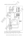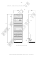
1
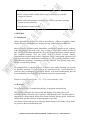
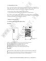
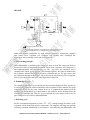
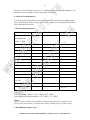
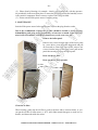
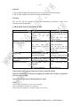
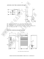
N
VN
EG
AB
W.
M
WW
WW
W.
ME
GA
B
MODEL
HD-100B
HD-192B
UY
.
UY
.V
USER'S MANUAL
INDUSTRIAL DEHUMIDIFIER
.V
CONTENTS
N
-1-
1.1. Introduction
1.2. Warranty
GA
B
1.3. Responsibility for safety
2.1. Outer component identification
2
UY
.
2. Product description
2
VN
UY
1. General
W.
ME
2.2. Inner component identification and working principle
3
4
5
d. Safety devices & function, e. Technical parameters, f. Capacity curve
6-7
EG
AB
a. Main working principle, b. Dehumidifying cycle, c. Defrosting cycle
3. Installation
3.1. Delivery and storage
8
3.2. Installation environment
8
3.3. Power sources
8
3.4. Installing
W.
M
WW
3
4. Operation
8
8
5. Maintenance
10
6. Troubles and Countermeasures
11
WW
7. Appendix:
Appdendix 1: Electrical Drawing HD-100B
12
Appdendix 2: Dimension Drawing HD-100B
12
Appdendix 3: Electrical Drawing HD-192B
13
Appdendix 4: Dimension Drawing HD-192B
14
HARISON INDUSTRIAL DEHUMIDIFIER - USER'S MANUAL - Model HD-Series
.V
Thanks for your purchasing our dehumidifier
N
-2-
• Please read the manual carefully before using it, and keep it in a suitable
storage for reference.
UY
• Please entrust professionals to install the unit in order to guarantee operating
the unit correctly and safely.
1.1. Introduction
UY
.
1. GENERAL
VN
GA
B
• The unit must be earthed reliably.
W.
ME
Harison dehumidifiers provide an effective and efficient solution to humidity control.
Harison HD-series dehumidifier are designed for large airflow of 900 and 1800m3/h.
EG
AB
WW
Model HD-series computer-control dehumidifier, meticulously designed by our company,
is the most advanced one in the range. They are used to remove water content from the air
and decrease the humidity automatically. They have elegant appearance, compact structure
and complete functions. They are widely used in scientific research, industry,
communication, medical health centers, commodity storage, underground engineering and
reference room, archive establishment, warehouses, etc. For preventing instruments, meters,
communication equipment, commodity, reference materials from getting damp, rusty,
mildew, rot and causing damage.
W.
M
The equipment has a computer-control, it is sensitive to the relative humidity, can controls
the humidity accurately. User can select as the requirement to the relative humidity by
which the power consumption is minimised. Besides, it can defrost automatically thus can
be used normally in low temperature environment, and can be operated easily.
Suitable environment-temperature : 5oC ∼ 32oC, relative humidity ≤ 90%
WW
1.2 Warranty
The warranty period is 12 months from the date of equipment commissioning.
The warranty is limited to free replacement and shipping of any faulty part, or subassembly which has failed due to poor quality or manufacturing errors. All claims must be
supported by evidence that the failure has occurred within the warranty period, and that the
unit has been operated within the designed parameters specified.
All warranty claims must specify the unit/type number and the serial number. These details
are printed on the unit identification plate.
HARISON INDUSTRIAL DEHUMIDIFIER - USER'S MANUAL - Model HD-Series
N
-3-
.V
1.3. Responsibility for safety
UY
Every care has been taken in the design and manufacture of HD-series dehumidifier to
ensure that they meet the safety requirements listed by federal codes. However, the
individual operating or working on any machinery is primarily responsible for:
* Personal safety, safety of other personnel, and the machinery.
* Correct utilisation of the machinery in accordance with relevant procedures.
VN
2. PRODUCT DESCRIPTION
UY
.
GA
B
The contents of this manual include suggested best working practices and procedures.
These are issued for guidance only, they do not take precedence over the above stated
individual responsibility and/or local safety regulations.
W.
ME
2.1 OUTER COMPONENT IDENTIFICATION
HD-100B
control
A
EG
AB
outflow
HARISON
filter
inflow
Humidity sensor
W.
M
WW
dry-air outlet
A
panel
condensed water
drainage
WW
• Dry-air outlet: supplying dry-air to room or duct (on-side of the unit)
• Control (panel): used to set working parameter for the unit.
• Air filter: used to prevent dust particle to enter coil.
• Humidity sensor: used to control unit operation on or off.
• Condensed water drainage: used to drain condensed water out
HD-192B
• Horizontal louver: used to adjust dry air outflow to be blown upward or downward.
• Vertical louver: used to adjust dry air outflow to be blown on right-side or left-side.
• Other components has the same function as those of HD-100B above.
HARISON INDUSTRIAL DEHUMIDIFIER - USER'S MANUAL - Model HD-Series
.V
N
-4-
vertical louver
UY
horizontal louver
HUM IDIT Y CONT ROL %
POWER/PROTECTION
75
45
UPPER
DEL AY/RUN/DEFROS T
outflow
LOWER
AUTO
HD - 192B
control
VN
GA
B
M ANUAL
UY
.
HARISON
filter
W.
ME
inflow
EG
AB
humidity sensor
WW
lower panel
condensed water
drainage
filter
centrifugal fan
evaporator
filter
WW
air strainer
W.
M
HD-100B
condenser
2.2. INNER COMPONENT IDENTIFICATION AND WORKING PRINCIPLE
capillary
valve
compressor
the flowing direction of air
the flowing direction of refrigerant in dehumidifying cycle
the flowing direction of refrigerant in defrosting cycle
HARISON INDUSTRIAL DEHUMIDIFIER - USER'S MANUAL - Model HD-Series
accumulator
W.
ME
compressor
the flowing direction of air
capillary
VN
filter
air strainer
filter
UY
.
GA
B
condenser
UY
valve
evaporator
HD-192B
.V
N
-5-
EG
AB
the flowing direction of refrigerant in dehumidifying cycle
the flowing direction of refrigerant in defrosting cycle
Other main working components are: high efficient compressor, accumulator, magnetic
flow control valve, evaporator coil, condenser coil, capillary tube, centrifugal fan,
temperature sensor, humidity sensor and electrical wiring.
WW
a. Main working principle
W.
M
When dehumidifier is switched on, the compressor starts to work. The compressor draws in
low-pressure and low-temperature refrigerant stream from evaporator, and compresses it
into high-temperature and high-pressure gas. The gas enters into condenser and is
condensed into liquid, giving out heat. Then through capillary, the liquid is throttled into
the evaporator, absorbs heat from the air and is evaporated into gas. The gas is drawn into
the compressor through air intake pipe. Just in this way the refrigeration cycle is completed.
Such a cycle repeats time and again, and refrigeration is achieved.
b. Dehumidifying cycle
WW
The centrifugal fan makes wet air entering into the evaporator through air filter, then the air
is cooled down. When the surface temperature of the evaporator is lower than the dew-point
temperature of the air, the water content in the air is condensed and drained from the
machine. The dehumidified air is then heated by the condenser and is discharged into the
room by the centrifugal fan. Thus, the air goes through the cycle and the water in the air
gets condensed so as to achieve dehumidification.
c. Defrosting cycle
hen the environment temperature is lower ( 5oC - 18oC ) during running, the surface of the
evaporator will be frosted due to lower temperature. The computer will judge and send the
defrosting command automatically as the situation. After defrosting, the dehumidifier will
HARISON INDUSTRIAL DEHUMIDIFIER - USER'S MANUAL - Model HD-Series
N
-6-
d. Safety devices and function
.V
turn back to run normally. In the way of " dehumidifying-defrosting-dehumidifying ", the
machine can work normally in lower temperature environment.
Model
GA
B
e. Main technical parameters
HD-100B
HD-192B
RH 60%
3.2
RH 70%
4.2
Power source
V
220 ± 10% / 1 phase
380 ± 10% / 3 phases
Frequency
Hz
50
50
Rated current
A
8.6
kW
1.85
3.8
kW
dehumidification
Kg/h
Rated input power
Max input power
EG
AB
W.
ME
volume
6.3
UY
.
Nominal
VN
UY
In order to protect the unit from severe damage during operation the unit is equipped with
such a safety features such as: low pressure cut-off, compressor overload protection, defrost
cycle, main short-circuit fuse.
8
7.0
2.2
4.36
3
m /h
900
1800
MPa
0.53
0.60
MPa
1.87
1.88
dB( A )
≤ 59
≤ 60
Refrigerant / Charge
Kg
R22 / 1.1
R22 / 1.9
Overall dimensions (D
mm
439 x 540 x 1023
430 x 600 x 1920
Kg
64
132
A
15/15
≥ 25 / 15
WW
Air flow
Suction pressure
Discharge pressure
W.
M
Noise level
x W x H)
Mass
WW
Main switch / fuse
Note :
Nominal working condition : 27.0oC ( DB ), 21.2oC ( WB )
Low temperature working condition : 5.0oC ( DB ), 2.1oC ( WB )
Notice :
Please use this unit under the specified environment and temperature condition strictly.
The use life will be shorten if exceeding the working condition for a long time in using.
f. Dehumidifying capacity curve
HARISON INDUSTRIAL DEHUMIDIFIER - USER'S MANUAL - Model HD-Series
N
-7-
.V
HD-100B
Dehumidification capacity (kg/h)
4.5
UY
4
GA
B
2.5
2
1.5
1
W.
ME
0.5
0
50
20oC
15oC
10oC
60
70
EG
AB
40
VN
3
25oC
UY
.
3.5
30oC
HD-192B
Relative humidity (%)
9
8
7
6
5
25oC
20oC
15oC
WW
4
30oC
W.
M
WW
Dehumidification capacity (kg/h)
3
10oC
2
1
0
40
50
60
70
Relative humidity (%)
HARISON INDUSTRIAL DEHUMIDIFIER - USER'S MANUAL - Model HD-Series
N
-8-
.V
3. INSTALLATION
3.1. Delivery and storage
UY
To ensure consistent quality and maximum reliability, each dehumidifier is inspected prior
to leaving the factory. If the dehumidifier is to be put into storage, prior to installation, the
following precautions should be observed:
VN
GA
B
The dehumidifier must be protected from physical damage
The dehumidifier must be stored under cover and protected from dust, frost and rain.
W.
ME
3.2 Installation Environment
UY
.
Inspection
Remove the shipment packing and inspect unit to ensure that no damage has occurred
during transportation and storage. Any visible damage must be reported to nearest Harison
representative.
3.3. Power source
EG
AB
( 1 ) The unit should be installed stably. There should be one meter of space in front of the
inflow and outflow. There should be no large obstacle around it.
( 2 ) The machine set should be far from heat source and inflammable gas.
( 3 ) The condensed water could be drained out of the room or into a pail.
( 4 ) It is advisable to not to install it in a place of heavy dust or serious pollution.
WW
( 1 ) The power should be supplied with a special wire.
( 2 ) Provide automatic air-break switch.
( 3 ) There should be reliable electrical grounding.
W.
M
3.4. Installing
( 1 ) Skilled professional personnel should perform maintenance of the unit.
( 2 ) Parking inclination of the unit should not exceed 10o.
4. OPERATION
WW
Switch on the power source
After the power source is switched on, the "POWER" light ( red ) is on; the unit is in the
standby mode.
"MANUAL" operation :
Press "MANUAL" switch, the delay light ( red ) is on. After 3 minutes, the run light (green
) is on, the compressor and the fan begin to work, and the unit is in the state of
dehumidifying. Press "MANUAL" switch again, the run light is off, the unit stops working,
the unit is in the standby mode.
HARISON INDUSTRIAL DEHUMIDIFIER - USER'S MANUAL - Model HD-Series
N
-9-
.V
" AUTO " operation :
UY
Press " AUTO " switch, the upper and lower limit lights ( green ) of the humidity are on,
and the humidity control indicates the scope of the humidity. The unit is in the auto run
mode.
HUMIDITY CONTROL %
GA
B
75
45
DELAY/RUN/DEFROST
LOWER
HD-192B
UY
.
AUTO
W.
ME
MANUAL
UPPER
VN
POWER / PROTECTION
Control panel (for both HD-100B & HD-192B)
EG
AB
Select the ventilating direction
Turning the louver of the outflow, you can adjust the sir direction to make the airflow
distributing evenly in the room.
Select the scope of the humidity
W.
M
WW
Selecting " AUTO " switch, the upper and lower limit lights ( green ) of the humidity are
on, and the humidity control indicates the scope of the humidity. At this time, you can press
" UP " or " LOWER " to select the suitable humidity as your requirement. When the
environment humidity exceeds the upper limit, the computer will judge automatically and
send the command of dehumidifying; when the environment humidity falls to the lower
limit, the computer will check automatically and send the command of stopping. In this
way of cycle, the environment humidity will be under the scope of humidity control.
Compressor can be protected automatically
WW
When discontinuous starting or switching on of the power is not more than 3 minutes, and
the " DELAY " light is on, then the compressor can not work in 3 minutes. When the "
DELAY " light is off after 3 minutes, the compressor can work again.
The unit can defrost automatically
When defrosting, the " DEFROST " LIGHT (orange ) is on.
Attention
( 1 ) As the switch for the electrical control of the unit is the touch type, please do not
knock hard on any key.
HARISON INDUSTRIAL DEHUMIDIFIER - USER'S MANUAL - Model HD-Series
N
- 10 -
.V
( 2 ) Please clean by blowing ( for example : clean by ear-cleaning ball ) with low-pressure
air periodically in the more dust place to ensure the precision because the humidity sensor
is the sensitive component. Please correct or replace if the sensor is failed.
( 3 ) Please switch off the power source if stopping using.
UY
5. MAINTENANCE
Switch off the power source before maintenance. Pull out the plug from the socket.
UY
.
Remove two screws from the upper of the lower panel
by a cross driver, press the panel downwards and pull
out forwards to remove the lower panel; remove two
screws from the lower of the upper panel, pull out the
panel downwards to remove the upper panel.
EG
AB
Draw out the air filter
Draw out the air filter upwards.
W.
M
Air filter
WW
WW
W.
ME
Remove the inflow panel.
VN
GA
B
Due to the accumulation of dusts, the air filter should be cleaned to avoid effecting
dehumidifying and going wrong periodically, at least once a month. If the dusts are
more in the environment, it should be cleaned every week, even every day.
Clean the air filter
When cleaning, gently tap the air filter or remove the dust with a vacuum cleaner, or you
can put the air filter in warm water ( ≤ 40oC, add a little neutral detergent ) to wash it or to
brush it, and then wash with clear water.
HARISON INDUSTRIAL DEHUMIDIFIER - USER'S MANUAL - Model HD-Series
N
- 11 -
.V
Attention
a. The air filter should not be exposed directly to sun of fire, to avoid deforming.
b. The air filter should be fixed before starting the dehumidifier.
UY
Warning :
VN
The use life will be prolonged if checking, maintaining periodically. Please send
professional person to damage.
GA
B
6. TROUBLES AND COUNTERMEASURES
Switch on the power source
plug in
Replace the fuse after
removing troubles
Clean the air filter
Remove the obstacle
Close the door and the
window, shade the sun with
curtains, etc.
Contact dealer and repair it
Refrigerant leakage
Machine inclined backward Level the unit
Drain pipe is blocked
Remove the front panel and
wipe off dirt from the pipe
The temperature sensor is Replace the temperature
open circuit or short circuit. sensor
The temperature sensor is Fix the temperature sensor
well
loosening.
EG
AB
WW
Water leakage
Countermeasures
UY
.
analysis of causes
Power failure
Power source is not
switched on not well
plugged
Fuse is broken
Machine can not dehumidify Air filter dusted
or the effect is bad.
Air
inlet
and
outlet
obstructed door or window
is open
W.
ME
Phenomenon
Machine does not run.
W.
M
"POWER/PROTECTION"
light flashes.
Machine can not defrost
The valve is damaged.
Replace the valve
If the troubles have not been removed yet, please contact the dealer.
WW
When the dehumidifier is starting or stopping, the sound of the cycling of refrigerant
does not mean a trouble.
It is normal that hot wind is discharged the air outlet.
Notice
Please switch off the power source after stopping.
Must be grounded reliably when installing.
Please keep this manual in a suitable storage for reference.
HARISON INDUSTRIAL DEHUMIDIFIER - USER'S MANUAL - Model HD-Series
N
- 12 -
.V
APPENDIX 1: ELECTRICAL DRAWING HD-100B
~220V/50Hz
L1
~ 14.5V
KM
RT
o
t
KM
L1
ST
AP
YV
MM
KR
W.
ME
GA
B
FU 2
VN
N
E
N
L3
C
W BL R
UY
.
~ 220V
L2
UY
L2
KR
FU 1
T
M1
O
M2
MOTOR
3~
MM
MOTOR
1~
MM
EG
AB
M1 : compressor; T : transformer ; AP : main control board; M2 : fan motor
FU 1 : fuse box (0.75A); YV : electromagnetic defrost valve; KR : hot relay
KM : AC contactor; C : fan capacitor; RT : defrost temp. sensor; ST : humidity sensor
FU 2 : fuse box (2A); Bl - black
O - orange R - red
W - white
315
439
WW
130
600
540
W.
M
WW
APPENDIX 2: DIMENSION DRAWING HD-100B
115
1023
18
Φ20
30
note: dimension measured in mm
HARISON INDUSTRIAL DEHUMIDIFIER - USER'S MANUAL - Model HD-Series
1(R)
4(LB)
3(Y)
2(GR)
MM
E 10(Y/G)
XP
101
4
3
N
L3
L2
L1
XS 2:6
1
FU
1
2
11(GR)
7(BL)
13(W)
M2:3
12(GR)
T
1(R)
2(R)
3
1
KM
2
A2
2(BL)
1(BL)
YV
X2
X1
~14.5V
6
3
1
2
~220V
5(R)
14(BL)
XT:L1
6(R)
15(R)
3(R)
8(BL)
1
17 FU2
1
5A
2
6
4
KR
6
4
1
2
YV
L
1T
2
KM
1
KR
2
3
109 XS7 XS8
108
XS5 XS6
1(BR)
1(BR)
3 3
1 1
2(BL)
2(BL)
2 2
2 2
3(B)
3(B)
1 1
3 3
1
1~
MOTOR
M2
3~
MOTOR
M1
Y/G
MM
16
o
t
2
APPENDIX 3: ELECTRICAL DRAWING HD-192B
ST
RT
.V
Y/G
MM
16
UY
107
106
XS3 XS4
1(W)
1(W)
1 1
2(W)
2(W)
2 2
MM
4(Y/G)
3(BL)
VN
7
ST 6
5
RT 4
AP
1(R)
2(B)
GA
B
2
96
UY
.
5
3
1
A2
95
105
104
XS1 XS2
7(BR)
7(BR)
7 7
6(O)
6(O)
6 6
5(BL)
5(BL)
5 5
4(C)
4(C)
4 4
3(C)
3(W)
3 3
2(R)
2(R)
2 2
1(GR)
1(GR)
1 1
6
5
4
9(BL)
EG
AB
KM:A1
W.
M
XT
WW
W.
ME
WW
N
- 13 -
M1 : compressor; T : transformer ; AP : main control board; M2 : fan motor
FU 1 : fuse box (0.75A); YV : electromagnetic defrost valve; KR : hot relay
KM : AC contactor; C : fan capacitor; RT : defrost temp. sensor; ST : humidity sensor
FU 2 : fuse box (2A); Bl - black
O - orange
R - red
W - white
HARISON INDUSTRIAL DEHUMIDIFIER - USER'S MANUAL - Model HD-Series
.V
N
- 14 -
APPENDIX 4: DIMENSION DRAWINGHD-192B
EG
AB
W.
M
WW
WW
UY
.
W.
ME
290
1920
430
VN
GA
B
UY
600
115
Φ20
270
note: dimension measured in mm
HARISON INDUSTRIAL DEHUMIDIFIER - USER'S MANUAL - Model HD-Series
Assembled in Thailand (ไทย)
VN
.V
UY
GA
B
UY
.
EG
AB
W.
M
WW
W.
ME
WW
N