1
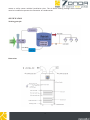
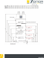
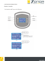
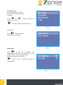
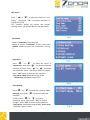
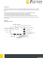
Manual instruction Air Source Heat Pump Unit Air Duct ZONDA 1. INTRODUCTION Dear customers: In order to use this machine safely, please read this user's manual carefully before using and installation, especially pay attention to each notice remark for usage and maintenance. Also keep it carefully for later use. Heat pump water heater is a professional machine, it may cause damage or hazard when wrong installed. Relevant installation and maintenance shall be done by technical people. Please contact our installation service for reference. Important warning: 1. When using for the first time, check if all the wiring are correct before you connect the unit 2. 3. 4. 5. 6. 7. 8. to power supply. If the power cord is damaged, please replace a new one offered from factory by professional technicians. Power plug's rated current shall be in accordance with the model you buy. bThe units must be ground wired. Never connect the ground line on neutral line or water pipe. Product shall be singly assigned to a electrical leakage protection power . Hot water above 50 may be burned, we suggest that you mix cold water with hot water from water tank for use. Any equipment must not be inserted inside the heat pump unit, in case any accident or abnormal operation. For your safety, please DO NOT change or mend the heat pump water heater yourself. 1 SPECIFICATION Technical data 252 Kw 3 l 250 W 790 A 3,6 V/Ph/Hz 220-230/1/50 1 rotary °C 55 °C 55 m3/h 450 Pa 60 mm Ø150 dB(A) 49 cal G 3/4" mm Ø640x1610 mm 705x705x1750 kg 84 kg 103 Heating capacity Water tank volume Power input Running current Power supply Compressor number Compressor type Rated outlet water temperature Max outlet water temperature Air volume Air pressure Duct diameter Noise Water inlet size/outlet size Net dimentions Pacage dimentrions Net weight Gross weight 253 3 250 790 3,6 220-230/1/50 1 rotary 55 55 450 60 Ø150 49 G 3/4" Ø640x1610 705x705x1750 88 103 NOTICE : 1. The technology parameter is tested as below:20 for dry temperature outdoor, 15 for wet temperature outdoor; inlet water 15 ; outlet water 55 . 2. 3. Refer to the label on the unit if the data different from this table. 2 SPECIFICATION Apperance and Features High efficiency: Smart design make normal working efficiency more than 30 % Easy installation and operation With LCD display, easy to handle and check all kind of temp and operation information Stainless steel tank Ensure clean water to users Waste heat is useful heat The standard heat exchanger of the hot-water heat pump enables direct connection to a second heat generator, e.g. a solar heating system or a boiler. Dehumidification in the recirculating air mode Dehumidified air in the laundry room supports laundry drying and prevents moisture-induced damage. Cooling in the recirculating air mode The room air is extracted from the storage room or a wine cellar,subsequently cooled and dehumidified in the heat pump and finally re-introduced into the room.Recreation rooms, boiler 3 rooms or utility rooms areideal installation sites. The air-ducts leading through warm sections must be insulated to prevent the formation of condensation. SPECIFICATION Working principle Dimentions 4 5 6 Maintain and overhaul To choose a right model -Please choose the model with right water tank volume according to the actual need for the energy saving and convenient use; -This air source heat pump is providing hot water for home use; Installation requirement and location -The unit must be installed indoor and free from rain; There must be sufficient water supply near the unit;The unit must be installed horizontally. At air inlet and outlet, please connect ducted pipes to avoid that the return air goes into air outlet! Water pipe connection Please keep below points in mind when the water pipe is connected: -To make the water resistance inside of the pipe as low as possible -To keep the water pipe clean and free from dirty; when the connection is made there must be testing on the leaking; Ensuring there is no leak on the pipe then the insulation can be made; - There must be one way valve and check valve installed on the water inlet pipe Electrical wire connection There is a power cable in the bottom of the unit which can be connected to the electric power by the users. Transit There must not be something on top of the unit, and keep it free from strike and extrusion during the transit Trial running Checkup before the trial running -Check whether the water tank is full, or whether the insulation for the pipe is good; -Check the electrical connection: check whether the voltage is normal, whether the wire connection is good and whether the earthing is made; -Check the unit: check whether the screw and parts is good enough; and check if the indicator light on the controller is working fine or any failure alarm as it get power; Trial running -Turn on the unit with the wire controller 7 -Keep ear on the sound from the compressor when it start; if there is any sound abnormal the unit must be stoped and checked; -Look into the tank water to see whether the water temperature fluctuation is normal; -The parameter of the wire controller has been settled in the factory, they cannot be reset by the users; Please return to the qualified service man if the parameter need to be changed. 8 CONTROLLER INTRODUCTION Function of controller User Interface and Usage as the following 9 Function Screen Press "Prg" button from Main Screen to access Function Screen, see Fig.3. Press" " or " functions, then press " " to choose setting of 4 " to enter setting of chosen function . Main Menu Press " " button to access the Main Menu,see Fig.4. Mode Select Press " " to enter FIG. 5 interface , for changing the setting of " Aux. Heating " and " Fan Mode" function . You may change status between ON and OFF by pressing " ", press " ESC " to confirm and return to main interface. 10 Unit Satus Press " " or " " to move the cursor to " Unit Status" , then press " " to confirm and enter to interface of FIG.6. This interface display the current real /actual running status , parameter data are not adjustable . Parameter Choose "Parameter "from Function Screen to access "Parameter "Screen, then press "ENTER" button to access the “Parameter” see Fig. 7. Operation Press " " or " " to move the cursor to "Operation" then press " " to confirm and enter interface of FIG.8. Press " " or " " to change the parameter value , then press "ESC" to confirm . Press " ESC" again to return to last interface . "Out water temp"adjustable range:10-60 " T1(heating)"adjustable range:2-15 C Aux Heating Press " " or " " to move the cursor to "Aux Heating" ,then press " " to confirm and enter interface of FIG.9. Press " " or " " to choose parameter value , then press " ESC" to confirm changes , press "ESC" to return to last interface. "Start temp. "adjustable range:30 90C "Start delay "adjustable range:0 90min 11 Defrost Press " " or " " to move the cursor to "Defros" ,then press " " to confirm and enter interface of FIG.10. Press " " or " " to choose parameter value , then press " ESC" to confirm changes , press "ESC" to return to last interface. "Def.cyc"adjustable range:30 90M(M for minutes) "Def.in"adjustable range:-30 0 "Def.out "adjustable range:2 30 "Max time"adjustable range:1 12M Save Press " " or " ,then press " " to move the cursor to " ave" " to confirm and enter interface of FIG.11.Press " " or " " to choose parameter value , then press " ESC" to confirm changes , press "ESC" to return to last interface. Adjustable value : "0" or "1" Disinfection Press " " or " " to move the cursor to "Disinfection" ,then press " " to confirm and enter interface of FIG.12. Press " " or " " to choose parameter value , then press " ESC" to confirm changes , press "ESC" to return to last interface. Swell Valve Press " " or " valve" ,then press " interface of FIG.13. " to move the cursor to " well " to confirm and enter Press " " or " " to choose parameter value , then press " ESC" to confirm changes , press "ESC" to return to last interface. " Mode" have " Auto" and "Manual " 2 options to choose. "Over Heat "Adjustable value :-20 20 "Adjust step "Adjustable value :100 500N 12 Timer Choose "TIMER " from FUNCTION SCRREN to access "TIMER" screen, then press ENTER"button to access the "TIMER" „Date” and „Clock” setting Press " " or " " to move the cursor to "Date" or " Clock" ,then press " " to confirm and enter interface of FIG.15. Press " " or " " to choose parameter value , then press " ESC" to confirm changes , press "ESC" to return to last interface. TIMER ON/OFF SETTING You may set both "Timer 1" and" Timer 2" 2 period time at the same time TIMER 1 ON/OFF SETTING Move the cursor to "Timer 1 on ", press " " once , "X " flashes . Then press " " or " ", " ’ " flashes , pressor " " once , timer on function start to take affect . At the moment, you may press " " or " " to set the time of Timer On, then press " " or " ESC" to confirm . Move the cursor to"Timer 1 off " , press " " once, " " flashes . Then press " " or " "," " flashes , press " " once , timer off function start to take affect . At the moment, you may press " " or " " to set the time of Timer Off, then press" " or " ESC" to confirm . TIMER 2 ON/OFF SETTING The setting operation is same as "TIMER 1 ON/OFF" 13 CONTROLLER INTRODUCTION AIR SOURCE HOT WATER UNIT Malfunction Display During standby or running state , if malfunction happens to the system, the system will stop to show the malfunction code as the following : Ordinary malfunctions and Solutions 14 15 Maintenance Heat pump water heater need to be timely check the operation status. If the units can be well maintained in a long term, you can see surprising improvement for reliable operation and long life span 1.Tap water inlet shall install with a filter and clear termly, to ensure good water quality. 2.The surrounding of the units must keep clean and dry , good ventilation. 3.Termly clean the side heat exchanger to keep good heat exchange efficient. 4.If the units will be shut off for a long time, please make sure to drain all the water inside the system, and cut off the power supply. Please perform profound s ystem inspection before you start the units again Appendix Controlling board access 16