1
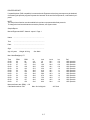
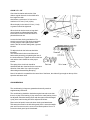
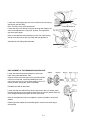
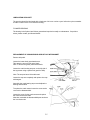
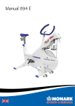
Monark 839 User Manual
MEC3V11n
Monark Exercise AB
Sweden
Eng. edit. 1
MEC3V11Rn
Terminal BT2V1
Edit. 1
CONTENTS
0. General
Warranty
Assembly Instruction
0:1
0:1
0:2
1. Introduction
Overview, How To Use This Manual
Specifications
Where To Obtain Additional Information
1:1
1:2
1:2
2. Getting Started
Final assembly
Installing optional equipment
Initial Operation
2:1
2:1
2:1
3. Testing With the 839 Ergometer
Performance Validation
Calibration Electronics
Preparation for Testing
Heart Rate detection
Subject Supervision
Reviewing Results
3:1
3:2
3:3
3:4
3:4
3:5
4. Computer Reference
Main Display, Keyboard Layout
RPM display and Visual metronome/Pulse
Printer - printout
Testing - General
Menu system, overview
Protocol Operation
Åstrand
YMCA
Bruce
Naughton
Manually:
Force reg., power reg.,
VO2 reg., HR-reg.
Work test:
Increment, Ramp
Create seq.programs:
System menu:
Service Menu:
External Interface
4:12
4:14
4:15
4:17
4:18
4:20
5. Mechanical Reference
Calibration Pendulum Weight
Zero Adjustment Meter Panel
Brake Belt, Contact Surface and Brake Belt
Replacement of Brake Belt
Pendulum Weight Bearing
Chain
Crank Bearing
Replacement of the Freewheeling Sprocket
Flywheel Bearing
Replacement of Crank Sensor
5:1
5:1
5:2
5:2
5:2
5:3
5:3
5:4
5:5
5:5
6. Appendix
Operation Interfaces
References
6:1
6:2
4:1
4:1
4:2
4:3
4:4
4:6
4:9
4:10
4:11
CUSTOMER SERVICES
If technical assistance is required, please contact your MONARK-dealer or
MONARK EXERCISE AB, S-780 50 VANSBRO, SWEDEN, + 46 281 594940, Fax + 46 340 71981.
MONARK EXERCISE AB, S-432 82 VARBERG, SWEDEN, + 46 340 86000, Fax + 463 40 80485.
PREFACE
Congratulations on your decision to purchase a product manufactured by Monark Exercise AB in Varberg,
Sweden. Monark has been the worlds leading manufacturer of high quality ergometer and exercise cycles for
more than 35 years.
The Monark 839 Computerised Ergometer is built on the world famous model 818 mechanical ergometer,
equipped with a microcomputer workload controller.
The perfect balance of a straight forward mechanical design and a sophisticated microcomputer assures the
owner of the complete validation of the 839´s performance.
As with all other technical products, your Monark exercise equipment needs regular maintenance. With
minimal care you will avoid unnecessary repairs and have years of dependable, trouble free performance from
your purchase.
WARRANTY
As on any quality product there may be an exceptional fault due to material or manufacture. If such a fault
should arise on your ergometer, please return to place of purchase for necessary repair.
Monark products and parts are guaranteed against defects in material and workmanship for a period of one
year from the initial date of purchase of the unit.
Please note: Monark will provide a transformer. Should you choose to utilise your own transformer, you must
assume all responsibility in the event of improper wiring which could result in burnt out electronics.
NB If the power cord from the wall outlet to the transformer is not correct and approved in the country used you
must find one that is approved for your own country.
Parts found to need replacement due to normal wear and tear, such as brake belts, are not covered. This
guarantee covers parts only, not labour costs associated with the repair.
This guarantee does not apply to cases of abuse or vandalism, nor does it extend to any injury or loss to
person or property caused directly or indirectly by any Monark products.
In the event of a defect in material or workmanship during the warranty period, Monark will repair or replace
( at its option ) the product. Monark will do so at its expense for the cost of materials but not for labour or shipping.
SEE YOUR PHYSICIAN FIRST !
Before you begin exercising you should have a complete medical examination. Your physician will probably
give you a go-ahead. Even persons with serious organic disorders, including many heart attack victims, are
able to exercise under carefully prescribed conditions.
However, if you have a history of cardiorespiratory problems, or if you have reason to suspect the existence of
such a problem it’s a good idea to have an exercise, or stress electrocardiogram (ECG). It will help your physician detect any complications that might be provoked by prolonged, strenuous exertion.
In addition, if you have had any recent surgery, or muscle, joint or back problems, always consult your
physician first.
0:1
PARTS BELOW ARE NOT ASSEMBLED.
Pedal, pair
Front support tube(with wheels) + two lock nuts
Rear support tube + two bolts + two lock nuts
Handlebar complete
Computer control unit + cable
Transformer + power cable
Chest belt incl. transmitter
HR receiver
Tool kit:
Instruction manual
Åstrand “Work tests with the bicycle ergometer”
Calibration weight 4 kg
ASSEMBLY INSTRUCTION
Tip the cycle forward.
Note: Use the accompanying spanner.
Assemble the support tube with two bolts and two nuts.
Tip the cycle backwards.
Assemble the front support tube with two nuts onto the two bolts in the
frame
Adjust to desired saddle height position by loosening the saddle post bolt.
In order to change the inclination of the saddle, loosen the saddle clip.
NOTE: Tighten firmly.
Remove the tube from the handlebar head. The tube is only there to secure the bike
during transport.
Before the handlebar stem is assembled be sure the wedge is loose. Insert
the handlebar stem into the head tube and tighten the wedge bolt firmly by
means of the lever. The handlebar stem should be inserted into the fork
tube at least 7 cm ( about 3 inches). Usually this measure is marked out.
To change the height of the handlebar, loosen the bolt lever about 5 turns.
Tap the bolt to release the expanding cone. Adjust the handlebar to the
desired position and tighten the wedge by means of the lever.
In order to change inclination of the handlebar, loosen the lever somewhat.
Adjust to desired position and tighten the handlebar firmly again by means
of the lever.
0:2
The pedal marked R ( Right ) is to be
assembled on the right hand side of the
cycle ( the chain wheel side ).
The pedal axle has a right hand thread and
must be threaded onto the crank clockwise.
Tighten firmly!
The pedal marked L ( Left ) is to be
assembled on the left hand side of the
cycle. The pedal axle has a left hand tread
and must be threaded onto the crank
counter clockwise. Tighten firmly.
Dismantle the front cover of the flywheel. Remove the
transport blocks inside. One block inserted above the
flywheel and one block under the flywheel.
Remove the tape from the flywheel.
NOTE: It is very important that all of the
plastic tape is removed. Residue of
the plastic tape may cause an
uneven operation.
Assemble the brake belt as before.
Assemble the cover again.
0:3
INTRODUCTION
OVERVIEW
The Monark 839 Electronic Ergometer is a complex structure of mechanical equipment under the control
of an elaborate computer system. The computer provides a fine element of control which was not possible
to obtain using strictly mechanical devices.
The mechanical component is basically the proven Model 818 ergometer, consisting of a stable, heavy
duty steel frame, a large well balanced heavy flywheel, a belt braking device, and a force measuring
pendulum assembly. Pedals and a chain drive are provided to spin the flywheel as a tension device
tightens the belt to regulate the braking force applied to the wheel. The pendulum indicates the applied
force directly on the scale located on the right side of the flywheel.
The computer system consists of one main unit and one terminal. The main unit reads in the pedal speed,
the applied force and determines the subjects heart rate by a chest transmitter or an ear plethysmograph.
Additionally, the base controller activates motor to adjust the tension of the belt, thereby regulating the applied braking force. The force may be automatically varied in response to changes in pedal speed to maintain a constant power workload.
The terminal( the remote or hand-held controller) communicates with the operator via a keyboard and display system. The operator instructs via a menu system the terminal to perform certain work functions
which are in turn sent to the main computer. The interaction between the computers is bidirectional, providing control instructions to the main computer and simultaneously providing speed, force, heart rate and
timing information to the terminal(hendheld).
HOW TO USE THIS MANUAL
The manual is divided into several sections. Initially, the section entitled “ Getting Started“ should be read
to establish some basic operating principles of the ergometer. This chapter enables the user to assemble
and check out the ergometer through some very simple procedures.
Once the user is confident in the elemental operation of the ergometer, reading should continue with
section “Testing with the 839 Ergometer “. This introduces the procedures for using the programmed
portions of the ergometer, the protocols.
Prior to reading the sections about the computer and protocols, the user should briefly read though the
portions concerned with the mechanical maintenance of the ergometer, the “ Mechanical Reference“. This
section describes periodic maintenance and repair techniques. Reading of this section is suggested so
that the user is aware of the proper maintenance philosophy at an early date, rather than after a
component failure.
Finally, the section “ Computer Reference “ should be tackled. The reader is advised to skim this section
on the first exposure due to the depth of the material presented. To avoid confusion, hands on learning is
probably the best technique after the initial reading. The reader should try depressing the keys as indicates
in the examples. The user need not to be concerned with the completion of a protocol. Learning how to
make the ergometer do what is desired is more important at this time. The proper setup of the test should
be the users focus.
Once the user feels comfortable with the basic operation of the ergometer, simple exercise should be
performed. The user should attempt to attach a chest belt during this exercise and verify that the
ergometer is under the control of the operator and that a stable heart rate is recorded. After the user
masters manual ergometer operation and is capable of instrument a subject to reliably measure heart rate,
protocol operation will be very simple. At that time, a review of the section entitled
“ Testing with the 839 Ergometer “ will prove extremely helpful.
1:1
SPECIFICATIONS
Construction:
Stable, heavy duty steel frame
Large, well balanced flywheel
Brake power 0-1400 W at 200 RPM
Comfortable saddle with adjustable height
Handlebars adjustable in height and distance from seat
Wheel for easy transport
Computer:
Computer system 8MHz
High visibility backlit display
Multi-colour RPM pacing bar graph display
Visual metronome or heart rate
Heart rate maximum limit alarm
Serial communcation port: 300 - 38400 baud
Preprogrammed protocols: Åstrand, YMCA, Bruce, Naughton,
Incremental, Ramp.
HR-training
Measured guantities:
Distance:
meters, miles
Energy:
kcal
Heart rate:
beats/minute(bpm)
Force:
newtons(N)
Power:
Watts (W), kpm/min or VO2 ml/min/kg
Time:
min, sec
Weight:
kilogram(kg), pounds(lb)
Electrical:
Voltage 24 VDC or 18 VAC.
Transformer to wall outlet. 100 - 240 VAC, 50/60 Hz, 15 W.
Note: The transformer must be approved by your national electrial authorities.
Dimentions:
Length:
Width:
Height, at handlebar:
Height at saddle:
Wegiht:
1120 mm (44´´)
530 mm (21´´)
650-1135 mm (30´´- 45 ´´)
800-1120 mm (31.5´´- 44´´)
55 kg (112 lbs)
WHERE TO OBTAIN ADDITIONAL INFORMATION
The user may require more information concerning several areas of the ergometer usage. This manual
was intended to instruct the reader primarily in the operationof the ergometer. Reference are made to related topics in the discussions concerning the testing procedures and the protocol operation sections.
The following readings may provide some greater insight to ergometer based testing without confusing the
reader with extremely technical medical terms. Both texts were written specifically to provide basic understanding of the testing methodology and results. Attention is paid to details concerning program setup and
management.
Golding LA, Myers CR, Sinning WE, The y´s way to physical fitness“, YMCA of the USA, Rosemont, IL,
1982.
Astrand P-O, “Work Tests with the Bicycle Ergometer“, Monark AB, Varberg, Sweden.
For more technical details, see the section entitled “Appendix: Reference“
1:2
GETTING STARTED
Monark 839 Final Assembly Instructions
READ THESE INSTRUCTIONS PRIOR TO ASSEMBLING THE ERGOMETER!
Assemble the supporting legs, pedals, saddle and handlebar as specified under
“Assembly Instruction”.
Remember to remove the transport tape on the pendulum.
INSTALLING OPTIONAL EQUIPMENT
The 839 Electronic Ergometer interfaces to several optional devices. A parallel interfaced printer may be
attached to provide written reports. A terminal may be used to control the ergometer.
A computer may be connected to communicate with the ergometer under programmed control and
monitor the subjects performance.
For more information regarding external control units se chapter “External Tecknical Reference”.
The terminal or the computer attaches both via a serial cable to the 9 pin interface connector located on the
front of the ergometer. Attach a printer if available to the parallel port on the front.
The ergometer need not be turned off prior to connection of the external components, although removing
the power from all devices may prevent erroneous data transfer between equipment during
interconnection. Caution must be exercised in the connection of various types of equipment from different
manufactures to avoid electrical hazards and physical damage. The user must be certain that the
instrument connector and the cable are designed for the intended purpose. Serious injury to the user and/
or equipment may result if inappropriate connections are attempted.
Attach the cable to the appropriate connector. Turn on both pieces of equipment if not already powered.
If the instrument is a terminal or printer, the system may need to be setup. Verify that the System setup
have been set to enable automatic printout. If it has been disabled, no output will reach the device until it
has been enabled. Also, the baud rate selected by the interface cable must match that of the device. See
“Command Interface“ for details. If the device is a printer, proper paper loading and unit selection must be
completed prior to operation ( refer to printer instruction manual).
The automatic printout length is a preset to eleven inch pages for standard fanfold or zee-fold paper. At the
top of the each page, a header designating the columns is printed. The abbreviations are discussed in the
“External Interface“ section 4.6.
The time period between the printing of each line may be set as desired, from 0 (continuous output) to
255 seconds in one second increments. The standard setting is 15 seconds between printouts. This provides reasonable documentation while not wasting large quantities of paper.
INITIAL OPERATION
Although all 839 ergometers are 100% calibrated at the factory, the user may wish to verify this by
performing the mechanical calibration of the pendulum weight. See section “Mechanical Reference, Calibration of Pendelum Weight”.
Apply power to the ergometer by first connecting the cable from the transformer to the ergometer at the
front connector labelled “ 24VAC/18VAC“. Then plug the transformer into the wall outlet.
Turn the power switch to on position. A green LED indicates power to the 839.
Perform the electrical calibration as specified in section “Testing with the 839 Ergometer,
Calibration Electronics”.
Test ride the ergometer. The 839 Electronic Ergometer is now fully functional and ready.
2:1
TESTING WITH THE 839 ERGOMETER
PERFORMANCE VALIDATION
The 839 is a mechanically weighted and braked ergometer, making performance validation a simple procedure. The work performed on the ergometer is the product of the weight lifted times the numbers of
revolutions (factored). Validation includes both mechanical and electronic procedures. If the ergometer
fails to pass any section of the validation, proceed to the calibration and/or service menu
(99 in the main menu).
Inspection of all mechanical components is suggested after any repair, component service.
Once per year, the following validation should be performed.
Pendulum Weight:
1.
2.
3.
4.
5.
6.
Remove the cover from the flywheel.
Loosen the brake belt at the balancing spring.
Wait until the flywheel is not moving any longer.
The pendulum weight index should be aligned with “0“ on the scale.
Attach the calibration weight to the point at which the spring was attached.
The known weight should match the value on the scale. If not see section “Calibration of Pendulum
Weight “.
7. Reattach the tension belt.
8. Reassemble the cover.
Proceed to the validation to complete.
Validation
The following procedure will assure the user that the ergometer is performing properly on a daily basis.
The test exercises the mechanical braking, pedalling and speed detecting systems as well as the computer regulation and sensing capability of the mechanical system.
Additionally, if a calibrated ECG simulator is available, it may be used to verify the heart rate measuring
system. Whether the simulator is used or not, the heart rate system may be validated by simply taking a
pulse point rate measurement at the neck for example. While a patient is at rest and has been prepared
for chest belt electrodes or an ear sensor, the pulse indicator flashes once per pulse beat. The displayed
rate, should agree with the manually detected pulse rate. If not, check the patient electrode connection and
skin preparation prior to requesting service.
Force:
From main menu go to any start display with newtons (N).
1. With the pendulum at zero, the display should read “ 0“.
2. Move the pendelumweight to the 4 kp position and the display should read “39“ Newtons.
3. Decrease the position of the weight by steps of 1 kp. The display should read correctly at all positions.
NB: After this check the brake belt will be somewhat loose and because of this it will take a few seconds
before normal workload is obtained the first time the ergometer is used.
Power:
Power calculation
1 RPM = 6 m on the flywheel brake surface.
50 rpm = 300 m
2 kp force makes 2 x 300 = 600 kpm/min
100 rpm = 600 m
1 kp force makes 1 x 600 = 600 kpm/min
3:1
CALIBRATION ELECTRONICS
Calibration is necessary to match the mechanics of the ergometer to the electronics of the computer.
The following steps are required to recalibrate the electronics to the pendulum scale.
1. Check at the bottom of the flywheel that the brake belt is loose. If not move the pendulum up to 3 kp
and hold it for a few seconds. Move the pendulum to the zero position again. Check that the brake belt is
loose.
2. Align the force scale with zero marker on the pendulum. Refer to section “Meter Board Zero Adjustment” for
details.
3. Press key 5 in the main menu (Calibration) and follow the display instructions.
a) Hold the pendulum at 0-position and wait for one “beep”.
a) Hold the pendulum at 2 kp-position and wait for one “beep”.
a) Hold the pendulum at 4 kp-position and wait for one “beep”.
b) Move the pendulum to the 6 kp position as told in the display. Hold it in position and wait for two “beeps”
short after each other.
c) Lower the pendulum to the resting position (0-marking).
Calibration is done.
The calibration coefficient which has been calculated by the computer is stored in the continuous memory.
Whenever power is applied to the ergometer, the latest calibration value is restored to maintain memory. A new
calibration replaces previous values.
Generally, it is not necessary to recalibrate the ergometer often. The coefficient is maintained even when
power is removed and the physical orientation of the frame, within the limits of normal riding, has no effect on
the electrical calibration. Recalibration should be preformed following any service, component replacement, or
transport of the unit or after setting to default in the service menu(99).
A daily validation of the pendulum force sensor should be preformed. If the procedure reveals an error,
recalibration may be necessary.
Check of the electronic calibration can be done as follows.
From main menu go to any of the test displays shoeing newtons (N).
Move the pendulum to 4 kp(39N).
This position shall now be read in the display. If not perform a new calibration.
NB! After this check the brake belt will be loose, which means that the first time the ergometer is used
after calibration it it will take a few seconds before normal workload is obtained.
3:2
PREPARATION FOR TESTING
The versatility of the 839 Electronic Ergometer enable it to be utilised in a variety of testing environments.
The precision and reproducibility of measurements made with the ergometer in conjunction with the ease
of testing, allow it to be employed in clinical exercise stress facilities, corporate fitness programs and
health clubs. The backgrounds of both the individuals being tested and those administering the test may
be vastly different in these widely varying testing situations.
In general, whether in a clinical laboratory or a health club, the subject may be exercised quite strenuously,
depending on workloads which have been selected. As a precaution, it may be advisable, prior to
beginning an exercise protocol, that each subject consult with a physician.
Before testing, the operator should review the entire protocol operation with the subject, explaining the
work which will be required and the duration of the procedure. A system of communicating fatigue, chest
pain or other abnormal physical response to the exercise should be discussed.
The subject should not engage in heavy physical activity for several hours prior to testing to establish
maximum oxygen consumption. In addition, all testing and exercise protocols should be performed a
reasonable time after meals. The subject should also refrain from smoking within an hour of the testing
period.
The subject should not be prepared for riding the ergometer, including the selection of proper clothing
which neither interferes with the physical activity nor endangers the health of the subject. The subject may
need some general education concerning the pedalling of the ergometer. The saddle and the handlebars
should be adjusted for comfort and proper mechanical distance. The saddle height should be set so that
when the ball of the subject’s foot is placed on the pedal, there is a slight bend at the knee with the pedal
in the lowest position.
The operation of the speed metronome and over/under display should be reviewed. The maintenance of
the proper speed should be practised at a low workload.
Finally, the chest belt should be applied and monitored to check for proper heart rate operation.
The baseline heart rate may also be of assistance in determining the nervousness of the subject.
The subject should exhibit a relatively stable resting heart rate prior to starting the protocol.
3:3
HEART RATE: ELECTRODE-BELT AND EAR PLETHYSMOGRAPH
The subject’s heart rate can be monitored by chest belt telemetry system or by an ear clip which measures
heart rate by light transmission through the ear. Only the system with chest belt electrodes is standard
equipment. The ear sensor system is an option.
Telemetry system (chest belt with transmitter)
The chest belt should be secured at a comfortable tension around the mid section, just below the breasts.
Moisten the electrodes before use. Heart rate monitoring, free from artifact, requires good electrode contacts
and adequate skin preparation. Prior to placing the electrodes, the subjects skin, at the electrodes sites,
should be cleaned with one of the commercial skin prep solution. After the chest belt is placed the heart
rate will be displayed and the heart will verify each beat. If the RPM bar is set to show optical heart beat in
the middle section this will also verify each heart beat.
NOTE! Elektromagnetic waves can interfere the telemetry system. Cellular phones are not allowed
to be used near the bike during test.
If the ergometer is to be used without chestbelt note that max heart alarm should be set in off position so
that external noise not can cause a random max pulse or higher. This switch is in on position by default. If
the heart rate exceeds the maximum level set, the alarm will sound and the ergometer braking force will
decrease until the heart rate drops below the alarm level.
Ear Plethysmograph (ear clip sensor)
(Not standard equipment. Can be baught as an option part.no 9303-93 + 9339-64)
The ear plethysmograph was designed for those applications in which heart rate is desired for simple
monitoring purposes. The technique may provide excellent heart rates for some individuals while others
may fail to indicate at rest or after moderate exercise, depending on peripheral circulatory function, room
temperature, smoking and many other variables. Basically, if the pulse display is in agreement with neck
pulse point throughout the session, the heart rate is valid.
The device plugs into the connector at the handlebar stem. Once plugged in, a small IR ( infrared) light is
illuminated in the ear clip. The opposite side contains a light sensitive cell. The device is then placed on the
ear to measure change in light transmission resulting from pulsating blood flow.
The placement of the ear clip is very subjective and should be chosen to maximise signal and consistency,
while also maintaining subject comfort. A good place is generally on the fleshy portion of the ear lobe on
individuals with detached lower lobes. Others seem to favour the upper portion of the ear. Trial and error
will determine the best location for each individual subject.
When proper function a green LED on the connector box is blinking in the same rate as the heart.
SUBJECT SUPERVISION
The ergometer performs automated tests virtually by itself, requiring minimal intervention by the operator.
This allows the operator to pay careful attention to the subject without distraction. The response to the
exercise protocol an be accurately estimated and appropriate action to assist the subject, if necessary,
may be given. The rider is subjected to considerable exercise in certain advanced protocol stages. The
effect on the subject should not be underestimated.
During the testing, the general appearance and heart rate may be the most crucial factors to monitor. The
testing should be stopped immediately if the subject reports chest pain, difficulty breathing, etc. A system
of prompt medical attention should be set up prior to testing, in case of emergency.
3:4
The subject may also show difficulty in regulating the speed of the ergometer. The power will be properly
regulated regardless of the speed, assuming that the protocol work type is not force and that the speed is
maintained above the pedal low setting (default is 30 RPM).
In addition , some subjects may become sensitive to the display on the handheld remote controller. If this
is suspected, the controller may be removed from its cradle and located out of view. Similarly, the pulse
LED may disturb the subject and may be disabled.
REVIEWING RESULTS
The maximum oxygen uptake is the standard measurement of cardiopulmonary fitness. Dependent on the
linear relationship between work and oxygen uptake and between work and heart rate, the heart rate
response to work may be used to estimate the oxygen consumption. If the maximum heart rate is
considered, the maximum oxygen consumption may be determined.
The YMCA and Astrand protocols estimate the maximum oxygen consumption, based on a submaximal
workload while all others report the oxygen consumption required by the final workload. The Bruce and
Naughton protocols require that the subject exercise at a workload level for a minimum of one minute to
establish the oxygen consumption; If less than one minute is observed, The previous workload value is
used.
The estimated maximum oxygen consumption derived from some of the ergometer tests is subject to the
error of the “ age related predicted maximum heart rate“. Although there is a definite and linear relationship
between work and oxygen uptake, there are some differences in actual oxygen uptake based on individual
work efficiency. Subject who are less familiar with bicycle exercise and those individuals who are less fit,
are more likely be less efficient than those who ride bicycles frequently.
It should be noted that these results are estimates or predictions of maximal response and have a greater
chance of being in error than if the individual were tested to their actual maximum value. Interpretation
should therefore be made more carefully with an understanding of the possibility of errors in the
methodology.
A relative fitness index can be obtained from the following tables :
Fitness Rating Index - Males
Maximum Oxygen Consumption
ml/kg/min
Rating
Excellent
Good
Above Av.
Average
Below Av.
Fair
Poor
- 36 yrs.
54
49
46
36
32
28
24
Fitness Rating Index - Females
Maximum Oxygen Consumption
ml/kg/min
vs. Age Ranges
Rating
36 - 45 yrs.
53
45
39
33
29
25
23
Excellent
Good
Above Av.
Average
Below Av.
Fair
Poor
45 - yrs
43
38
34
30
27
24
20
vs. Age Ranges
- 36 yrs.
55
45
39
34
30
26
20
36 - 45 yrs.
49
43
37
33
29
26
22
45 - yrs.
46
38
32
27
24
20
18
See also table 7 in “ Work tests with the Bicycle Ergometer“ by P O Astrand ( reference 6.3.8.)
3:5
COMPUTER REFERENCE
TERMINAL
MAIN DISPLAY (on the terminal)
1 Fitness test
2 Man./Work test
3 Seq. programs
4 Analog control
See also Menu System Overview.
KEYBOARD LAYOUT
Used keys:
Key 1 - 9: menu chice and numeric input
Arrow key up/down: scroll function
Dot key: decimal input
Del.key: delete function
Enter: enters input
Special function during fixed protocols:
Key 9: increase step on force/power level
Key 6: decrease step on force/power level
Key 3: start/stop program
Key 7 8 9: increase level
Key 4 5 6: decrease level
RPM DISPLAY and VISUAL Metronome/Pulse (on the bike)
METRONOME (the two green LED bars in the middle)
flashes once per pedal stroke preset rate.
The two green LED bars in the middle can also be set to show pulse.
Makes then one flash for every heart beat.
Pedal frequency compared to metronome rate is always shown.
Underspeed: Pedal speed is lower than desired metronome
rate.
2, 4, 8, 16 or more depending which LED bar
that indicates.
Overspeed:
Pedal speed is greater than desired metronome
rate.
2, 4, 8, 16 or more depending which LED bar
that indicates.
ERGOMETER CONTINUOUS MEMORY
To ease operation of the ergo meter, several “variables” are stored in “nonvolatile memory” . These variables are restored to normal memory each time power is applied to the ergometer.
4:1
PRINTER REPORT
If a parallel printer (DOS compatible) is connected to the Ergometer a hard copy test report may be obtained,
documenting the protocol progress at preset time intervals. At the end of a fixed protocol, a calculation is prepared.
NOTE:
The auto printout function must be enabled for the printer to operate outside fixed protocols.
To change the time interval between successive printouts, see System menu.
Sample Report:
Monark Ergometer 839E. Åstrand - report:1 Page: 1
Name: .......................................................................
Test:
........................................................................
Date:
.......................................................................
Sign:
.......................................................................
Age: 43 years
Weight: 82.0 kg
Sex: Male
Max. Heart Rate(bpm):177
Time
00:30
01:00
01:30
02:00
02:30
03:00
03:30
04:00
04:30
05:00
05:30
06:00
RPM
64
64
57
53
52
53
53
51
52
53
54
57
BPM
82
107
127
139
143
151
150
153
154
155
157
156
Measured heart rate (BPM) : 156
Calculated maximum V02:
N
4.0
38.0
43.0
46.0
47.0
48.0
46.0
48.0
48.0
46.0
46.0
43.0
kcal
1.0
8.0
16.0
25.0
33.0
41.0
50.0
58.0
67.0
75.0
83.0
92.0
Max: 49.4 ml/kg/min
4:2
km/h
23.1
23.1
20.4
19.1
18.7
19.1
19.1
18.3
19.8
19.0
19.5
20.4
km
0.2
0.4
0.6
0.8
1.0
1.1
1.3
1.4
1.6
1.7
1.8
2.0
4.05 l/min
Ref.
1500
1500
1500
1500
1500
1500
1500
1500
1500
1500
1500
1500
kpm/min
kpm/min
kpm/min
kpm/min
kpm/min
kpm/min
kpm/min
kpm/min
kpm/min
kpm/min
kpm/min
kpm/min
PROTOCOL OPERATION
A protocol operation cycles the ergometer through a predefined workload sequence, automatically. The
protocol may be designed to alter the workload according to time or a physiological response such as
heart rate. Several of the protocols may be modified or customized by the user to suit specific needs.
The programmed sequence of workload may be set to provide a varying workload. The rate of change of
the workload may be specifically set in some protocols. Still other protocols may exercise the subject to a
maximum (or submaximal) effort to determine an index of fitness (oxygen consumption).
A protocol may terminate based on the passage of time or the satisfaction of a specific physiological conditions such as a “steady state” heart rate. For details, refer to the specific protocol operation description.
At the conclusion of a protocol, a summery is printed, if the optional external printer is installed. This report
includes various identification data: the protocol name , the subjects age, weight, sex. In addition, test results are printed, including the predicted maximum heart rate, the actual steady state heart rate, the maximum workload and the “V02 max”. The V02 maximum is expressed both as a total body usage in l/minute
and per kg of body weight in ml/kg/minute. If a printer is not available, only the V02 max data, both in l/min
and ml/kg/min are displayed. The interpretation and meaning of the V02 max data is specific to the design
of the particular protocol. Certain protocols are simply programmed exercise and therefore are not designed to measure V02. Please refer to the specific protocol description prior to attaching any significance
to the reported value.
The computer controller for the 839 Ergometer can preform different protocols in addition to strict manual
operation. Four protocols have been preset and 2 are partly preset . Several preprogrammed protocols
measure oxygen consumption at steady state: the Astrand, using a single workload, the YMCA, using
multiple branching workloads (“YMCAs Way to Physical Fitness” bicycle test) and the Bruce and
Naughton, using multiple increasing workloads (treadmill protocols adapted to bicycles ergometry). Additional preprogrammed protocols, not designed to measure V02, provide timed increasing workloads (ramp
and incremental) and a heart rate training program in which a target heart rate is set and the ergometer
attempts to maintain the target rate by varying the applied workload accordingly.
All protocol operations enable the heart alarm feature. The alarm value is preset to 220 - age. During the
test setup procedure, the maximum heart rate may be changed depending on the subjects exercise
prescription or other constraints.
If the heart rate exceeds the alarm value, a beeping tone will be heard until the heart rate falls below the
alarm point or the alarm is disabled. When the alarm sounds, the workload is removed, automatically, to
prevent overstressing the subject.
The alarm feature may be disabled, particularly if the protocol does not require monitoring of the subject’s
heart rate. If heart rate is not being monitored, start the protocol and then disable the alarm.
The automatic protocol attempt to exercise the subject at specific oxygen consumption levels. The
ergometer achieves this by producing a braking force which, in normal individuals, requires the consumption of the desired volume of oxygen. Note that most protocols express the V02 in ml/kg/min, therefore,
the total V02 required is calculated using the subjects weight and subsequently converted to a power
workload. The table below shows the nominal work equivalent to various oxygen consumption rates.
Work load
Oxygen uptake
(kpm/min)
(L/min)
300
0.9
600
1.5
900
2.1
1200
2.8
1500
3.5
1800
4.2
2100
5.0
2400
5.7
4:3
MENU SYSTEM
4:4
MENU SYSTEM
4:5
ASTRAND PROTOCOL
The Astrand protocol is designed to determine maximal oxygen consumption by exercising the subject at a
submaximal workload and measuring the steady state heart rate. The workload, in conjunction with the resultant heart rate, is compared to the predicted relationship, adjusted for age and sex and a maximal oxygen consumption is computed.
The protocol defines nine workloads at which the subject may be evaluated. The workloads for male subjects
span 300 kpm/min to 1500 kpm/min in 150 kpm/min steps. The workloads for females cover 300 kpm/min to
900 kpm/min in 75 kpm/min steps.
The workload selection is preformed manually during the first two minutes of the test. The workload should be
difficult enough to elicit a steady heart rate of at least 120 bpm. If too high a workload is chosen, the subject
may not be able to complete the minimum of six minutes necessary to reach steady state conditions. the protocol has been designed to test individuals with a normal mechanical efficiency during steady state; very high
workloads can only be preformed aerobically by individuals with a very high work capacity.
During the workload seleection interval, the workload should be increased until the heart rate varies no more
than 4bpm and is consistently greater than 120 bpm.
At the end of the fifth minute, the heart rate is recorded. If, by the end of the next minute, the heart rate is
within 4 bpm of the previous observatioons, the protocol is finished. If not, the test continues until the pulse
rate has been within 4 beats for one minute. Note: If the heart rate is erratic or the workload is improperly adjusted for steady state exercise, the test will fail to complete. Of course, the protocol may be interruped by the
START/STOPkay, although the error message “Test Aborted” and no calculation of V02 max will result.
NOTE:
The final heart rate must be within the range for the sex and workload below, otherwise
“ERROR:HR LOW/HI” result.
Males
Workload
kpm/min
300
450
600
750
900
1050
1200
1350
1500
Heart Rate
Min
118
118
118
118
118
120
120
124
130
Females
Workload
Max
140
160
170
170
170
170
170
170
170
Heart Rate
kpm/min
300
375
450
525
600
675
750
825
900
Min
118
118
118
118
120
120
120
120
128
Max
148
158
170
170
170
170
170
170
170
The maximum oxygen consumption is obtained through the look up of the steady state heart rate and workload in the appropriate male or female table of “Predicted V02 Max from Heart Rate and Workload”. This estimate is then multiplied by a factor which is related to the age of the subject. The factor is found in the following
table according to the predicted maximum heart rate:
V02 Correction Factor
Maximum HR
Factor
over 200
1.12
191-200
1.00
181-190
0.93
171-180
0.83
161-170
0.75
151-160
0.69
less than 151
0.64
Instruct subject about the protocol and adjust the chest belt for reliable pulse.
Setup subject data according to the menu. See menu Astrand test.
Select ASTRAND and push key 3 = start.
4:6
Predicted V02 Max (l/m) from Heart Rate & Workload (kpm/min) - Females
HR
300
375
450
525
600
675
750
825
900
118
119
120
121
122
123
124
125
126
127
128
129
130
131
132
133
134
135
136
137
138
139
140
141
142
143
144
145
146
147
148
149
150
151
152
153
154
155
156
157
158
159
160
161
162
163
164
165
166
167
168
169
170
2.7
2.6
2.6
2.5
2.5
2.4
2.4
2.3
2.3
2.2
2.2
2.2
2.1
2.1
2.0
2.0
2.0
2.0
1.9
1.9
1.8
1.8
1.8
1.8
1.7
1.7
1.7
1.6
1.6
1.6
1.6
0.0
0.0
0.0
0.0
0.0
0.0
0.0
0.0
0.0
0.0
0.0
0.0
0.0
0.0
0.0
0.0
0.0
0.0
0.0
0.0
0.0
0.0
3.1
3.0
3.0
2.9
2.8
2.8
2.7
2.7
2.6
2.6
2.5
2.5
2.4
2.4
2.3
2.3
2.3
2.2
2.2
2.2
2.1
2.1
2.1
2.0
2.0
2.0
1.9
1.9
1.9
1.9
1.8
1.8
1.8
1.8
1.7
1.7
1.7
1.7
1.6
1.6
1.6
0.0
0.0
0.0
0.0
0.0
0.0
0.0
0.0
0.0
0.0
0.0
0.0
3.5
3.4
3.4
3.3
3.2
3.1
3.1
3.0
3.0
2.9
2.8
2.8
2.7
2.7
2.7
2.6
2.6
2.6
2.5
2.5
2.4
2.4
2.4
2.3
2.3
2.2
2.2
2.2
2.2
2.1
2.1
2.1
2.0
2.0
2.0
2.0
2.0
1.9
1.9
1.9
1.8
1.8
1.8
1.8
1.8
1.7
1.7
1.7
1.7
1.6
1.6
1.6
1.6
3.9
3.8
3.7
3.6
3.6
3.5
3.5
3.4
3.3
3.2
3.2
3.1
3.1
3.0
3.0
2.9
2.9
2.8
2.8
2.7
2.7
2.7
2.6
2.6
2.5
2.5
2.5
2.4
2.4
2.4
2.3
2.3
2.3
2.2
2.2
2.2
2.2
2.1
2.1
2.1
2.1
2.0
2.0
2.0
2.0
1.9
1.9
1.9
1.9
1.9
1.8
1.8
1.8
0.0
0.0
4.1
4.0
3.9
3.9
3.8
3.7
3.3
3.5
3.5
3.4
3.4
3.4
3.3
3.2
3.2
3.1
3.1
3.0
3.0
2.9
2.8
2.8
2.8
2.7
2.7
2.7
2.6
2.6
2.6
2.6
2.5
2.5
2.5
2.4
2.4
2.4
2.3
2.3
2.3
2.2
2.2
2.2
2.2
2.2
2.1
2.1
2.1
2.1
2.0
2.0
2.0
0.0
0.0
4.5
4.4
4.3
4.2
4.2
4.1
4.0
3.9
3.9
3.8
3.7
3.6
3.6
3.5
3.5
3.4
3.4
3.3
3.3
3.2
3.1
3.1
3.1
3.0
3.0
2.9
2.9
2.9
2.8
2.8
2.7
2.7
2.7
2.6
2.6
2.6
2.6
2.5
2.5
2.5
2.4
2.4
2.4
2.4
2.3
2.3
2.3
2.2
2.2
2.2
2.2
0.0
0.0
4.8
4.8
4.7
4.6
4.5
4.4
4.3
4.2
4.2
4.1
4.0
4.0
3.9
3.8
3.8
3.7
3.6
3.6
3.5
3.5
3.4
3.4
3.3
3.3
3.2
3.2
3.2
3.1
3.1
3.0
3.0
3.0
2.9
2.9
2.8
2.8
2.8
2.7
2.7
2.7
2.6
2.6
2.6
2.6
2.5
2.5
2.5
2.4
2.4
2.4
2.4
0.0
0.0
5.2
5.1
5.0
4.9
4.8
4.7
4.7
4.6
4.5
4.4
4.3
4.3
4.2
4.1
4.1
4.0
3.9
3.9
3.8
3.8
3.7
3.7
3.6
3.5
3.5
3.4
3.4
3.4
3.3
3.3
3.2
3.2
3.1
3.1
3.1
3.0
3.0
3.0
2.9
2.9
2.8
2.8
2.8
2.8
2.7
2.7
2.7
2.6
2.6
2.6
2.6
0.0
0.0
0.0
0.0
0.0
0.0
0.0
0.0
0.0
0.0
4.8
4.8
4.7
4.6
4.5
4.4
4.4
4.3
4.2
4.2
4.1
4.0
4.0
3.9
3.9
3.8
3.8
3.7
3.7
3.6
3.6
3.5
3.5
3.4
3.4
3.3
3.3
3.2
3.2
3.2
3.1
3.1
3.0
3.0
3.0
2.9
2.9
2.9
2.8
2.8
2.8
2.8
2.7
4:7
Prediced V02 Max (l/m) from Heart Rate & Workload (kpm/min) - Males
HR
118
119
120
121
122
123
124
125
126
127
128
129
130
131
132
133
134
135
136
137
138
139
140
141
142
143
144
145
146
147
148
149
150
151
152
153
154
155
156
157
158
159
160
161
162
163
164
165
166
167
168
169
170
300
2.3
2.3
2.2
2.2
2.2
2.1
2.1
2.0
2.0
2.0
2.0
1.9
1.9
1.9
1.8
1.8
1.8
1.7
1.7
1.7
1.6
1.6
1.6
0.0
0.0
0.0
0.0
0.0
0.0
0.0
0.0
0.0
0.0
0.0
0.0
0.0
0.0
0.0
0.0
0.0
0.0
0.0
0.0
0.0
0.0
0.0
0.0
0.0
0.0
0.0
0.0
0.0
0.0
450
3.0
2.9
2.9
2.8
2.8
2.7
2.7
2.6
2.6
2.6
2.5
2.5
2.5
2.4
2.4
2.3
2.3
2.3
2.2
2.2
2.2
2.1
2.1
2.1
2.1
2.1
2.0
2.0
2.0
1.9
1.9
1.9
1.9
1.9
1.8
1.8
1.8
1.8
1.7
1.7
1.7
1.7
1.7
0.0
0.0
0.0
0.0
0.0
0.0
0.0
0.0
0.0
0.0
600
3.6
3.6
3.5
3.4
3.4
3.4
3.3
3.2
3.2
3.1
3.1
3.0
3.0
2.9
2.9
2.8
2.8
2.8
2.7
2.7
2.7
2.6
2.6
2.6
2.5
2.5
2.5
2.4
2.4
2.4
2.4
2.3
2.3
2.3
2.3
2.2
2.2
2.2
2.2
2.1
2.1
2.1
2.1
2.0
2.0
2.0
2.0
2.0
1.9
1.9
1.9
1.9
1.8
750
4.3
4.2
4.2
4.1
4.0
4.0
3.9
3.8
3.8
3.7
3.7
3.6
3.6
3.5
3.5
3.4
3.4
3.3
3.3
3.2
3.2
3.1
3.1
3.0
3.0
3.0
2.9
2.9
2.8
2.8
2.8
2.8
2.7
2.7
2.7
2.6
2.6
2.6
2.6
2.5
2.5
2.5
2.5
2.4
2.4
2.4
2.4
2.3
2.3
2.3
2.3
2.2
2.2
900
5.0
4.9
4.8
4.7
4.6
4.6
4.5
4.4
4.4
4.3
4.2
4.2
4.1
4.0
4.0
3.9
3.9
3.8
3.8
3.7
3.7
3.6
3.6
3.5
3.5
3.4
3.4
3.4
3.3
3.3
3.2
3.2
3.2
3.1
3.1
3.0
3.0
3.0
2.9
2.9
2.9
2.8
2.8
2.8
2.8
2.8
2.7
2.7
2.7
2.6
2.6
2.6
2.6
4:8
1050
0.0
0.0
5.6
5.5
5.4
5.3
5.3
5.2
5.1
5.0
4.9
4.9
4.8
4.7
4.6
4.6
4.5
4.4
4.4
4.3
4.3
4.2
4.2
4.1
4.1
4.0
4.0
3.9
3.9
3.8
3.8
3.7
3.7
3.7
3.6
3.6
3.5
3.5
3.5
3.4
3.4
3.3
3.3
3.3
3.3
3.2
3.2
3.2
3.1
3.1
3.1
3.0
3.0
1200
0.0
0.0
6.4
6.3
6.2
6.1
6.0
5.9
5.8
5.7
5.6
5.6
5.5
5.4
5.3
5.3
5.2
5.1
5.0
5.0
4.9
4.8
4.8
4.7
4.6
4.6
4.5
4.5
4.4
4.4
4.3
4.3
4.3
4.2
4.1
4.1
4.0
4.0
4.0
3.9
3.9
3.8
3.8
3.7
3.7
3.7
3.6
3.6
3.6
3.5
3.5
3.5
3.4
1350
0.0
0.0
0.0
0.0
0.0
0.0
6.8
6.7
6.6
6.5
6.4
6.3
6.2
6.1
6.0
5.9
5.8
5.8
5.7
5.6
5.5
5.4
5.4
5.3
5.3
5.2
5.1
5.1
5.0
4.9
4.9
4.8
4.8
4.7
4.7
4.6
4.5
4.5
4.5
4.4
4.4
4.3
4.3
4.2
4.2
4.1
4.1
4.1
4.0
4.0
4.0
3.9
3.9
1500
0.0
0.0
0.0
0.0
0.0
0.0
0.0
0.0
0.0
0.0
0.0
0.0
6.8
6.8
6.7
6.6
6.5
6.4
6.3
6.2
6.1
6.1
6.0
5.9
5.8
5.7
5.7
5.6
5.6
5.5
5.4
5.4
5.3
5.2
5.2
5.1
5.1
5.0
5.0
4.9
4.9
4.8
4.8
4.7
4.6
4.6
4.5
4.5
4.5
4.4
4.4
4.3
4.3
YMCA PROTOCOL - “Y´S WAY TO PHYSICAL FITNESS”
The YMCA protocol is based on the “Y´s Way to Physical Fitness” bicycle test. The design is a submaximal
test, using branching multiple workloads in which the next workload is determined by the steady state heart
rate elicited by the previous level. For details, refer to the “ Workload Branching” tables, later in this section.
Every three minutes the workload is advanced until the subject has completed three levels,
requiring a total of nine minutes. If the subject has an abnormally high heart rate response to the initial workload (100 bpm or more), the test is terminated at the end of the second level. If the operator senses that the
subject is experiencing difficulty completing the third level of the protocol, the START/STOP key may be used
to conclude the test early. If the test is stopped prior to the completion of the second level, an error message is
displayed, indicating that the test was “aborted” and no calculation of V02 max is possible.
At the conclusion of the test, estimates of the V02 max and the maximum workload are extrapolated from the
data collected during the previous two levels. The V02 max is reported on the display and the maximum workload contained in the report, available only if the optional external printer is installed.
YMCA protocol
Instruct subject about the protocol and adjust the chest belt for reliable pulse.
Setup subject age, maximum heart rate, weight and sex according to menu.
Select YCMA protocol:
Protocol operation may be terminated by depressing START/STOP (3).
Completion:
The protocol will terminate automatically under two circumstances:
a. nine minutes (3 levels) have been completed, or
b. six minutes (2 levels) have been completed and the heart rate elicited by the first level was 110 bpm or
more.
In addition, START/STOP may be used to end protocol operation after six minutes if the subject is having difficulty.
4:9
BRUCE PROTOCOL
Bicycle ergometers measure total oxygen consumption relatively independent of body weight. Since the subject’s body weight is supported by the saddle, the total work performed is a function of only the resistive force
and the pedal speed. At the same power setting, all subjects will have approximately the same oxygen consumption.
On the other hand, the treadmill measurement of oxygen consumption includes the subject’s weight as a component of the total work and therefore measures oxygen consumption per kilogram of body weight. At a given
incline and speed, each subject will have approximately the same V02 per unit of body weight.
The well known Bruce treadmill maximal oxygen consumption protocol has been converted for use on a bicycle ergometer, taking into account the differences between the treadmill and the bicycle devices. The ergometric workload is computed using the subjects body weight to calculate the total V02 at each stage of work, adjusting the power settings accordingly. The total oxygen consumption is calculated from the V02 (ml/kg/min) for
the stage multiplied by the body weight in kilograms. The workload is then selected from V02 workload table in
the “Protocol Operation” section.
The protocol increases the workload every three minutes from warm-up stage to successively more difficult
levels until the subject can no longer preform the test. At that time, the START/STOP key(3) is depressed to
conclude the protocol. The protocol does end automatically if a subject is capable of completing Stage VII
(79.9 ml/kg/min), an unlikely event.
The workload of the final stage is then converted to the equivalent V02 max and reported, both as total consumption in l/minute and per body weight in ml/kg/minute. If the subject has not completed at least one minute
of the protocol has been completed at termination, a “Test Aborted” message is displayed.
The stages of the Bruce protocol are as follows:
Stage
Speed
mph
Grade
%
V02
ml/kg/min
Warm up
Stage I
Stage II
Stage III
Stage IV
Stage V
Stage VI
Stage VII
1.7
1.7
2.5
3.4
4.2
5.0
5.5
6.0
5
10
12
14
16
18
20
22
12.2
17.4
24.8
34.3
43.8
56.7
68.2
79.5
Instruct subject about the protocol and adjust the chest belt for reliable pulse.
Setup subject age, maximum heart rate, weight and sex according to the menu system.
See Bruce menu.
Completion:
The protocol will terminate automatically if Stage VII is completed. Normal termination is accomplished by depressing START/STOP(3) when the subject can no longer perform the work. If the subject has not completed
at least one minute at the final workload, the previous workload is used. If less than one minute of the protocol
has been completed at terminal, a “Test Aborted” message is displayed. The program automatically selects the
current or previous workload, as appropriate.
4:10
NAUGHTON PROTOCOL
The standard Naughton Protocol (reference 5) is a two minute incremental test. The test is extremely similar to
the Bruce protocol with two simple exceptions: the stages are two minutes in duration instead of three and the
incremental V02 between stages is linear (3.5 ml/kg/min). The stages represent discrete oxygen consumption
levels generally referred to as “METS”.
The stages of Naughton protocol are as follows:
Stage
Speed
mph
Grade
%
V02
ml/kg/min
Stage I
Stage II
Stage III
Stage IV
Stage V
Stage VI
Stage VII
Stage VIII
Stage IX
2
2
2
2
2
2
3
3
3
0
2.5
7
10
14
17.5
12.5
15
17.5
7.0
10.5
14.0
17.5
21.0
24.5
28.0
31.5
35.0
The operation of the protocol is otherwise identical to the Bruce protocol.
Instruct the subject about the protocol and adjust the chest belt for proper heart rate.
Then follow Naughton menu.
4:11
MANUAL USE
Begin to put in personal data like sex, weight, age
and max. heart rate.
Workload - Force setting
The workload can be set in Newtons(N) or kp.
Power is in this mode depending on the pedal rpm.
Workload can be increased or decreased with
keys 7/4, 8/4 and 9/5.
Key 7/4, increase/decrease step 1.00 kp or 10 N.
Key 8/5, increase/decrease step 0.10 kp or 1 N.
Key 9/6, increase/decrease step 1.00 kp or 0.1 N.
Press start/stop when finished.
ç Increase
ç Decrease
Workload - Power setting
Power level can be set in watts or kpm/min.
Power level is not depending on pedal rpm.
Key 7/4, increase/decrease step 100 watts or 100 kpm/min.
Key 8/5, increase/decrease step 10 watts or 10 kpm/min.
Key 9/6, increase/decrease step 1 watts or 1 kpm/min.
Press start/stop when finished.
Workload - VO2
This is also a type of power setting. The advantage in this mode is that the workload
can be set in ml/min/kg which means that the power is related tothe subjects bodyweight.
A certain level of ml/min is always the same as a given power level.
See tabel in chapter ”Testing - general”.
Key 7/4, increase/decrease step 10 ml/min/kg or 1 l/min.
Key 8/5, increase/decrease step 1 ml/min/kg or 0.1 l/min.
Key 9/6, increase/decrease step 0.1 ml/min/kg or 0.01 l/min.
Press start/stop when finished.
4:12
Workload - HR related.
The Heart Rate program is designed to adjust the workload in an attempt to maintain a desired heart rate. This is
achieved by increasing the workload from zero, at the start, using incremental steps. How fast the power is
adjusted is depending on howfar away the actual heart rate is from the desired heart rate.
at heart rate lower than the desired setting the workload will increase with 60W (375 kpm/min) per minute until the
subjects heart rate is higher than 75 % of the desired heart rate. The power will then increase at 30 watts (180 kpm/
min) per minute antil the actual heart rate is within 5 bpm from the desired value. The power is kept at a constant
level as long as the subjects heart rate is within +/- 5 bpm from the programmed heart rate value.increment. The
work test continues until the it is stoped by the start/stop button (key 3).
The target heart rate is entered as part of the test preparation. Default value is 120 bpm. The target training rate
may be changed to suit the training program by just entering the value on the keyboard.
Key 7/4 increases/decreases 100 bpm.
Key 8/5 increases/decreases 10 bpm.
Key 9/6 increases/decreases 1bpm.
NOTE: The maximum target heart rate that can be set is 90% of the calculated max. heart rate (220 - age).
The resultant workload which is determined by the computer to maintain the target heart rate, may be used as a
basis for comparison over time, in an effort to objectively evaluate the effectiveness of training program.
Setup subject and follow menu.
Protocol operation may be terminated by depressing START/STOP key(3).
4:13
WORK TEST
INCREMENTAL PROTOCOL
The incremental protocol consists of a series of workloads which are constantly increasing with time. Under
control of the incremental, the ergometer exercises the subject to a maximum workload. The rate at which the
workload rises is presetable.
The type of work: power or force may also be preset as desired. The incremental protocol may be used to create a linearly increasing workload test such as a modification of Naughton protocol. The Naughton may be
viewed as an incremental protocol with a work type of V02 and a rate of 3.5 ml/kg/min every two minutes.
Set the subjects age, maximum heart rate, sex weight and selects the protocol.
Type of workload must be programmed. This stores the time and workload rate of change in continuous
memory. Each step is calculated from the previous step plus the step time and step work, constantly increasing.
During executions of the protocol, the INCREASE and DECREASE keys (key 9 or 6) may be used to advance
or retard the protocol. In this manner, if a workload is too easy, the protocol may be advanced in a non-linear
fashion until the workload is as desired.
Instruct subject about the protocol and adjust the chest belt for reliable pulse.
Follow menu instructions and start test.
RAMP PROTOKCOL
The ramp protocol is very similar to the incremental protocol in that it is based on a continuously
increasing series of workjloads. The major difference is that the ramp protocol steps are extremly
fine, making the tension from one workload step to the next nearly imperceptible.
Ramp protocol are sometimes employed to provide a very rapid rise in workload in an attempt
to determine the maximum workload which a subject can achive without significant elevation in
bloood lactic acid from anaerobic metabolism. Due to the rapid rise in workload, there is little
fatigue, although the medical risk may be high if an extremely high workload is attained too quickly.
Similar to the incremental, the ramp protocol must be programmed prior to running. The
programmingis slightly different in that the workload increase per minute is entered rather than the
step time and step work increments.
Operation is similar as well, exept that the protocol may not be advanced or retarded.
Instruct subject about the protocol and adjust the chest belt for reliable pulse.
Follow menu instructions and start test.
4:14
SEQUENS PROGRAMS - USER DEFINED PROTOCOLS
The operator may custom design his own exercise protocols and store them in computer memory.
This extra ordinary feature makes it possible to provide 10 additional protocols which may be setup as special purpose,
readily avilable protocols.
These protocols may be power or force type, time based designs.
This flexibility enables the user to program severall versions of the hills and valleys(increasing and decreasing workload)
type of exercisees and/or modifications to the Bruce/Naughton type protocols or different types of incremental work tests.
The possibilities are virtually limitless.
Main menu.
3 Seq. programs
1 Execute, 2 Edit and 3 Exit.
Make new program.
Begin with 3 Seq. program in the main menu and choose 2 Edit.
Choose new program by just pressing Enter.
The display looks as below.
Row number
Program number
Type of workload
Marker
New PGM
Stop
ï0
Seconds 0
000
Workload level
Increment time
The marker (arrow in the display) indicates which position can be edited.
When creating a new program begin to change ”stop” to desired workload.
This is done by the keys 1 - 5.
Key 1 = Newton, key 2 = kp, key 3 = watts, key 4 = kpm/min and key 5 = ml/kg/min.
Key 0 = Stop which is used to end the program.
Example:
Choose i.e. kp (key 2) and press Enter.
The marker turns to the right where workload level can be set. Type say 1.5 and Enter.
Marker moves to position seconds. Enter say 300(=5 minutes).
Marker moves up and indicates row number. Press Enter and number increases automatically one step.
Marker moves to type of workload again. The same as before is set by just pressing Enter. A change can be done by
pressing key 1-5 until the right type of workload shows up and then press Enter.
Marker moves to workload level. Enter level , Enter seconds a.s.o. until the program is long enough.
When the program is to be finished move the marker to point at type of workload and change with key 0 which is Stop
and then press Enter.
Programming is finished and program number ( 0 - 9) must be Entered.
Back to menu again.
NOTE: If a figure already containing a progarm is used this will erase the old program.
4:15
Edit an existing program.
Press 2 Edit.
Choose program number. Step through the program with the Enter key and make desired changes.
Then go to workload setting and change to Stop (key 0) and then press Enter.
NOTE! After editing an old or new program turn off the computer for correct dowload of data.
Execute program
Begin with 3 Seq. programs in the main menu and then 1Execute.
Choose an existing program and press Enter.
It is recommended to have a note about different program types and numbers. However it is possible to take a look in
advance at a program. Do as under ”Edit an existing program”.
If it says ”stop” in work load position ther is no program stored under that number.
Use ESC key and try with a new number.
4:16
SYSTEM MENU
1 SETUP
1 Setup
2 Language
3 Exit
SETUP:
Pedal ref.:
Metronome setting
Default setting <65> rpm.
Pulse alarm:
on/off
Optical pulse:
on/off
Pulse indication in the middle section of the rpm
bar.
Optical metronome:
on/off
NOTE! If both opti. pulse and optic metro. are set to
on only optic pulse will be set to on.
Print report:
on/off
Test report to printer.
When running fixed protocols the printer is
automatically set to on.
Weight unit:
Can be set to
0 = kg
1 = pounds
Distance unit:
Can be set to
0 = km
1 = miles
Logg interval:
Time delay for every printout row.
1 - 655 seconds can be set here.
Default setting <15> sec.
LANGUAGE:
1 English
2 Swedish
4:17
SERVICE MENU (99 hidden)
1 Adjust pot. (potentiometer)
If any service regarding the pendulum has been done the correct potentiometer position can be
checked here.
Follow display instructions.
2 Calibrate pot.
After adjusting pot. a calibration shall be performed here.
Also after setting to default in the service menu a calibration has to be done here.
Follow display instructions.
3 Set to default
Erases the memory. Formats and sets some data to default.
NOTE! A calibration must be performed after this action.
4 Printer
Form feed
Line feed
Page setting. Lines and margins can be set here.
Print report. To check printer connection.
5 Motor
Motor current limit.
Motor forward, backward and stop.
6 Service setup
Pedal ref.
Metronome setting.
Pedal min.
Lowest pedal rpm to obtain workload on the bike can be set here.
Default setting is 30 rpm.
Cykelkonst.
This value can be adjusted so that the power on the bike can be corrected to the pedals or to the
flywheel. NOTE! In the Astrand test the power is calculated on the flywheel.
Default setting is 1.00 which means there is no extra adjustment done for transmission loss.
If for example setting is 1.04 this means that loss is calculated to 4%.
Max. accepted pulse deviation
This figure is the deviation allowed during steady state to calculate a test.
Default setting <5> bpm.
Weight unit
Distance unit
Opt. pulse
Opt. metronome
Sound pulse
Sound metronome
<BEL> pulse
<BEL> metronome
Pulse check
0 = kg 1 = pounds
0 = km 1 = miles
on/off
on/off
on/off
on/off
on/off
on/off
on/off
7 LCD backlight Increase or decrease with left/right arrow key.
8 Analog setup
See “Technical Reference Manual”.
9 Unlock NVM
4:18
4:19
EXTERNAL INTERFACE
The Monark Ergometer 839E can be controlled externally from a terminal or a computer.
The control is performed over a serial line using ANSI/ISO/ASCII format commands.
The interface is a 9 pin male D-sub connector, compatible with the RS232 standard, located on the front of the
electronic.
To connect to a PC use a 0-modem serial cable with 9 pin female connectors in both ends.
It is also possible to use a analog control from an externa source to set the workloaad.
This is done by the contacts b32 and z32 on the main connector on the bike.
For a complete description of the command interface setup order the
Command Reference Manual from Monark Exercise AB, Sweden.
4:20
MECHANICAL REFERENCE
CALIBRATION OF PENDULUM WEIGHT
Remove the cover from the flywheel.
Loosen the balancing spring from the brake belt.
Check that the 0-index of the scale is in line with the index of the
pendulum weight.
Adjust if needed. NB. Wait until the flywheel is not moving any
longer.
Attach a known weight, e.g. 4 kg (our ref. No 9000-211) where the
balancing spring was placed.
Note: The weight should not be lighter than 3 kg, due to the possibility of inferior accuracy.
When correctly set, it should be possible to read this weight from
the corresponding place
on the meter panel.
Should there be a deviation, adjust the pendulum to the correct position on the scale
by means of the adjusting weight. In order to change the position of
the adjusting weight,
loosen the lock screw of the weight.
Should the index of pendulum, weight be too low, move the adjusting weight upwards into
the weight. Should the index be too high the adjusting weight is
moved somewhat downwards
and locked in the new position. This procedure is repeated until
the correct reading is achieved.
Check the calibration of the pendulum weight once a year or when
needed.
Assemble the front cover again.
ZERO ADJUSTMENT OF METER PANEL
Move the pendulum to 4 kp and keep it there for a few
seconds. check that the belt is loosened.
If adjustment is necessary, loosen first the lock nut and
thenchange the position of the adjusting screw, so that the
meter panel will have its 0-index in line with the index of the
weight. Tighten the lock nut after the adjustment.
5:1
BRAKE BELT CONTACT SURFACE AND BRAKE BELT
Deposits of dirt on the brake belt and on the contact
surface may cause the unit to operate unevenly.
The brake belt contact of the flywheel surface should
then be ground off with a fine abrasive cloth, see fig,
and any dust be removed with a clean dry cloth.
Remove the brake belt at the belt tensioner before the
grinding. See below.
Grinding off any build up of dust etc. is easier if a
second individual cautiously pedals the cycle.
Irregularities on the brake belt contact surface are also
removed by means of a fine abrasive paper or an
abrasive cloth. Otherwise unnecessary wear on the
brake belt may occur and the unit can become noisy.
We recommend you to replace the brake belt when cleaning the contact surface. See below.
Always keep the brake belt contact surface clean and dry. No lubricant is allowed to be used.
REPLACEMENT OF BRAKE BELT
Loosen the brake belt at the spring.
Loosen the screw (4 pcs) for the upper cover.
Remove the cover.
Hold the pendulum above the 7kp marking so the screw
for the fastening of the
brake belt can be loosened.
Replace the brake belt and assemble the other parts in
the reversed order according to the above.
PENDULUM WEIGHT BEARING
The bearing in the pendulum weight are lifetime greased and require normally no maintenance.
If a problem arises, please contact your Monark dealer.
5:2
CHAIN 1/2" x 1/8"
Check the lubrication and tension of the
chain at regular intervals. In the middle of its
free length the chain
should have a minimum of 10 mm and a
maximum of 25 mm (1 inch) of play.
When the play in the chain is 25 mm (1 inch)
or greater it should be tightened.
When the chain has become so long that it
can no longer be tightened with the chain
tensioners it is worn out and should be replaced with a new one.
Loosen the lower chain guard bracket. Remove the screw for the right chain guard, back.
To take away the chain guard, push it backwards. Take off the front chain guard, right and
left side.
To adjust the chain the hub nuts should be
loosened.
The hub and axle is then moved forward or
backward by loosening or tightening the nuts of
the chain tensioners. Tighten the nuts on the hub
axle and the chain should be at the proper
tension.
The spring of the chain lock should be
assembled with the closed end in the movement
direction of the chain. Use a pair of tongs for
dismantling and assembling the spring.
Note: If the wheel is not parallel to the centre line of the frame, the chain will get caught on the top of the
sprocket and cause noise.
CRANK BEARING
The crank bearing is long-term greased and normally needs no
supplementary lubrication.
The crank bearing should be checked at regular intervals to see that
there is no play in the bearing. If play exists in the crank bearing it must
be adjusted, otherwise bearing races and other parts will be damaged.
A play in the crank bearing should be adjusted as follows:
Remove the left pedal. Loosen the lower chain guard attachment.
Take away the screw for the left chain guard, back. Loosen the saddle
post screw some turns so the cover can be lifted up about 10 mm. To
loosen the chain guard, push it backward. .
5:3
Loosen the crank bearing stop nut on the left side of the unit using a
special tool (part No 7099).
Note: The stop nut has a left hand thread.
Loosen the stop nut so that by turning the dust cap with magnet, the
cone can be adjusted into a “play-free” position. Then tighten the
stop nut properly again.
Note: Do not adjust the crank bearing too hard. The crank bearing
should move play-free but still very easily after the adjustment.
Assemble the left chain guard and pedal.
REPLACEMENT OF THE FREEWHEELING SPROCKET
Loosen the brake belt at the belt tightener. Loosen the
lower chain guard attachment. Take
away the screw for the two chain on the right side and the
front cover on left side. Loosen the saddle post screw
some turns so the cover can be lifted up about 10 mm. To
loosen the back chain guard, push it backwards.
Dismantle the chain as described.
Loosen the axle nuts and lift off the wheel. Remove the axle nut, washer, chain
tensioner and spacer on the freewheel side. Place the remoter (part No 9400-14)
in the adapter and place the spacer and axle nut outside.
Note: No not tighten the axle nut completely. It must be possible to loosen the
adapter.
Replace sprocket-adapter and assemble again in reverse order according to
above points.
5:4
LUBRICATION SPROCKET
The sprocket should be lubricated with a few drops of oil once or twice a year. Incline the cycle somewhat
to make it easier for the oil to reach the bearing.
FLYWHEEL BEARING
The bearing in the flywheel are lifetime greased and required normally no maintenance. If a problem
arises, please contact your Monark dealer.
REPLACEMENT OF CRANK SENSOR OR DUST CAP WITH MAGNET
Remove left pedal.
Loosen the lower chain guard attachment.
Take away the screw for left guard, back.
Note: To loosen the guard, push it backwards.
Loosen the crank bearing stop nut on the left side of
the ergometer using a special tool (part No 7099)
Note: The stop nut has a left hand thread.
Loosen the stop nut completely and replace dust cap
with magnet.
Assemble the crank bearing stop nut and adjust the
bearing as described.
To replace the crank sensor loosen the screw so the
cover can be disassembled.
Loosen the screw for the crank sensor and replace
the crank sensor with cable.
After that, assemble the disassembled parts as above
but in reverse order.
5:5
APPENDIX
OPERATION INTERFERENCES
It is normally considered that about 70% of all shutdowns on small computers is caused by mains
interferences, i.e. at shot over voltage. These interferences can often be caused by different machinery,
which is stared or stopped. The processor in the computer is then reacting incorrectly or is not working at
all.
The problems can be solved by means of a mains interference protector, which is connected between the
mains and the transformer.
TROUBLE SHOOTING GUIDE
Symptom
Probable Cause/Corrective Action
No Display
Check that transformer is plugged into proper voltage AC
outlet and that the power connector is plugged into the 839
controller.
Display lights up but does
not respond to keyboard
Turn off power, wait 10 seconds and reapply power.
Does not load work
Check RPM ( no force is applied if RPM is less than
the pedal low ref.. Default 30 RPM)
Check calibration
No heart rate
Electrode skin preparation may be poor
(see electrode placement section)
The bulb in the ear clip may have failed or there may be a
cable failure.
No RPM reading
Check cable.
Unable to calibrate force
Potentiometer belt may be slipping or broken. Replace if
damaged.
Potentiometer misadjusted.
Reboot memory from service menu (99). Set default (3).
Uneven HeartRate
The telemetry syatem can be interfered by electromagnetic
waves. NB! Do not use cellular phones ner the bike during
a test.
6.1.2. ERROR MESSAGES
Message
Reason
Test Aborted
An automatic protocol operation has been stopped
prematurely. No results are available.
6:1
REFERENCES
1.
Astrand I, “ aerobic work capacity in men and women with special reference to age”,
Acta Physiol Scand. 49 (suppl. 169), 1960.
2
Astrand P-O, “Experimental studies of physical working capacity in relation to sex
and age”, Munksgaard, Copenhagen, 1952.
3.
Astrand P-O, Rodahl K, “Textbook of Work Physiology”, McGraw-Hill, New York,
1970.
4.
Bruce RA, Kusumi F, Hosmer D, “Maximal oxygen intake and nomographic
assessment of functional aerobic impairment in cardiovascular diseases*”, Am Heart
J 85:546-562, 1973.
5.
Naughton J,”Exercise Testing and Exercise Training in Coronary Heart Disease”,
Academic Press, New York,1973.
6.
Golding LA, Mayers cr, Sinning WE, “The Y´s way to physical fitness” YMCA of the
USA, Rosemont, IL, 1982.
7.
Wilson PK, Bell CW, Norton AC, “Rehabilitation of the heart and lungs”, Beckman
Instruments, 1980.
8.
Astrand P-O,”Work Test With the Bicycle Ergometer”, Monark-Cresent AB, Sweden
6:2