1
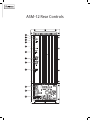
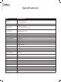
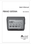
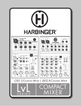
2-WAY 500-WATT POWERED MONITOR
BI-AMP DESIGN-INTEGRATED SIGNAL PROCEESSING
CELESTION LOUDSPEAKER & COMPRESSION DRIVE
INSTRUCTION MANUAL
Contents
Important Safety information
ASM-12 Rear Controls
ASM-12 Operation
Set-up Diagram
Specifications
Warranty
3-4
5
6-7
8
9-10
11
Welcome
CONGRATULATIONS ON YOUR PURCHASE OF THE FRIEDMAN
ASM-12 LOUDSPEAKER.
Please review all the information provided in this manual to
ensure that you attain the best possible sound quality from
your monitor. The Friedman ASM-12 was designed specifically
as a monitor to be used with guitar modeling amplifiers and
preamps.
The Friedman ASM-12 features simple rear panel controls, with
line level outputs for linking multiple speakers. Please see the
set-up diagrams at the end of this manual for examples of
possible system configurations.
The Friedman ASM-12 was designed using advanced acoustic and
audio techniques with premium components, comprehensive
protection circuitry, and robust construction to provide years of
consistent, reliable performance. Key features include: Bi-Amp
power modules with high efficiency Class G low frequency
amplification with high current output stage and custom signal
processing; clip/limit, thermal, and short circuit protection; optimized
acoustic designs using PETP film compression driver diaphragms;
heat vented low frequency drivers; and sturdy birch plywood.
Important Safety Instructions
Please keep this instruction manual for future reference and for the
duration of owning the ASM-12 powered loudspeaker. Please carefully
read and understand the instructions inside this owner’s manual before
attempting to operate your new powered loudspeaker.
This instruction manual includes essential safety information regarding
the use and maintenance of the amplifier. Take special care to heed all
warning symbols and signs inside this manual and those printed on the
amplifier on the back of the loudspeaker.
WARNING
TO PREVENT FIRE OR SHOCK HAZARD, DO NOT EXPOSE THE
AMPLIFIER TO WATER/MOISTURE, NOR SHOULD YOU OPERATE THE
AMPLIFIER NEAR ANY WATER SOURCE.
The exclamation point triangular symbol is intended to alert the user to the
presence of important operating and maintenance(servicing) instructions
in the user manual accompanying the Amplifier.
The lightning flash with an arrow triangular symbol is intended to alert
the user to the presence of non-insulated “dangerous voltage” within the
product’s enclosure, and may be of sufficient magnitude to constitute a
risk of electric shock
WARNING
Handle the power supply cord with care.
Do not damage or deform it as it may cause electric shock or malfunction
when used. Hold the plug attachment when removing from wall outlet. Do
not pull on the power cord.
IMPORTANT SAFETY PRECAUTIONS
1. READ INSTRUCTIONS – All the safety and operating instructions
should be read before this product is operated.
2. RETAIN INSTRUCTIONS – The safety and operating instructions
should be retained for future reference.
3. HEED WARNINGS – All warnings on the amplifier and in the
operating instructions should be adhered to.
4. FOLLOW NSTRUCTIONS – All operating and use instructions should
be followed.
5. DO NOT turn on the ASM-12 amplifier module before connecting all
other external devices.
10. POWER SOURCES – This product should be operated only from the
type of power source indicated on the rating label. If you are not
sure of the type of power supply to your home, consult your product
dealer or local power company.
11. GROUNDING OR POLARIZATION – Do not defeat the safety
purpose of the polarization or grounding-type plug. The wide blade
or the third prong is provided for your safety. If the provided plug
does not fit your outlet, consult an electrician for replacement of the
obsolete outlet. Do not defeat the safety purpose of the grounding
prong.
12. POWER-CORD PROTECTION – Power-supply cords should be
routed so that they are not likely to be walked on or pinched by
items placed upon or against them, paying particular attention to the
cord in correspondence of plugs, convenience receptacles, and the
point where they exit from the amplifier.
13. CLEANING – The speaker and amplifier should be cleaned only
as recommended by the manufacturer. Clean by wiping with a dry
cloth. Avoid getting water inside the speaker or amplifier.
14. NON-USE PERIODS – The power cord of the amplifier should be
unplugged from the outlet when left unused for a long period of
time.
15. OBJECT AND LIQUID ENTRY – Care should be taken so that objects
do not fall and liquids are not spilled into the enclosure through
openings.
16. DAMAGE REQUIRING SERVICE – The amplifier should be serviced
by qualified service personnel when:
A. The power-supply cord or the plug has been damaged; or
B. Objects have fallen, or liquid has been spilled into the
amplifier; or
C. The amplifier has been exposed to rain; or
D. The amplifier does not appear to operate normally or
exhibits a marked change in performance; or
E. The amplifier has been dropped, or the enclosure
damaged.
17. Keep the speaker system out of extended or intense direct sun light.
18. No containers filled with any type of liquid should be placed on or
near the speaker system.
19. SERVICING – The user should not attempt any service to the speaker
6. WATER AND MOISTURE – Moisture can damage the ASM-12 amplifier
and/or amplifier beyond that described in the operating instructions.
module and can cause corrosion of electrical contacts. The speaker
All other servicing should be referred to qualified service personnel.
system should not be used near water - for example, a bathtub,
20. VENTILATION – Slots and openings in the amplifier are provided
washbowl, kitchen sink, laundry tub, wet basement, or near a
for ventilation and to ensure reliable operation of the product and
swimming pool, and the like.
to protect it from overheating. These openings must not be blocked
7. CARTS AND STANDS – The speaker system should be used only with a
or covered. The openings should never be blocked by placing the
cart or stand that is recommended by the manufacturer. A speaker and
product on a bed, sofa, rug, or other similar surface. This product
cart combination should be moved with care. Quick stops, excessive
should not be placed in a built-in installation such as a bookcase
force, and uneven surfaces may cause the speaker and cart combination
or rack.
to overturn.
21.
ATTACHMENTS
– do not use attachments not recommended by the
8. WALL OR CEILING MOUNTING – The product should never be
product manufacturer, as they may cause hazards.
mounted to a wall or ceiling.
9. HEAT – The amplifier on the back of the ASM-12 loudspeaker should
be situated away from heat sources such as radiators, heat registers,
stoves, or other sources (including amplifiers) that produce heat.
22. ACCESSORIES – Do not place this product on an unstable cart,
stand, tripod, bracket, or table. The product may fall, causing serious
injury to a child or adult, and serious damage to the product. Use
only with a cart, stand, tripod, bracket, or table recommended by the
manufacturer, or sold with the product.
23. LIGHTNING – For added protection during a lightning storm, or
when it is left unattended and unused for long periods of time,
unplug it from the wall outlet. This will prevent damage to the
product due to lightning and power-line surges.
24. REPLACEMENT PARTS – When replacement parts are required, be
sure the service technician has used replacement parts specified by
the manufacturer or have the same characteristics as the original
part. Unauthorized substitutions may result in fire, electric shock, or
other hazards.
25. SAFETY CHECK – Upon completion of any service or repairs to
this product, ask the service technician to perform safety checks to
determine that the product is in proper operating condition.
26. FUSES – Always use the correct rating and type of fuse as indicated
on the rear panel of the amplifier. Note the proper rating fuse is
determined by the AC line voltage in the country this speaker system
is being operated. COMPLETELY DISCONNECT POWER CORD
FROM AMPLIFIER BEFORE ATTEMPTING TO REPLACE FUSE!
27. AC SELECT SWITCH: This switch must be set to match the AC line
voltage in the country this speaker system is being operated. To
change the setting, loosen (do not remove) the two screws above
and below the slide switch. Temporarily move the protective cover
strip and slide the actuator to match the voltage in your country.
Place the protective cover strip back over the switch and tighten the
two screws. COMPLETELY DISCONNECT POWER CORD FROM
AMPLIFIER BEFORE ATTEMPTING TO CHANGE AC VOLTAGE
SETTINGS!
28. The Friedman ASM-12 powered loudspeaker is not designed for
temporary or permanent suspension. Any attempt to suspend an
ASM-12 loudspeaker cabinet could result in injury or death.
To prevent electric shock, do not use a polarized plug with an extension
cord, receptacle or other outlet unless the blades can be fully inserted to
prevent blade exposure.
RISK OF
RISQUE DE CHOC
RISK OF
DE CHOC
ELECTRIC
SHOCK RISQUE
ELECTRIQUE
NE
ELECTRIC
DO NOT SHOCK
OPEN ELECTRIQUE
PAS OUVRIR NE
DO NOT OPEN
PAS OUVRIR
RISK OF
ELECTRIC SHOCK
CAUTION: To reduce the risk of electric shock,
do not
DO NOT OPEN
CAUTION: To reduce the risk of electric shock,
do not
RISQUE DE CHOC
ELECTRIQUE NE
PAS OUVRIR
remove chassis. No user-serviceable parts inside.
remove chassis. No user-serviceable parts inside.
Refer servicing to qualified
service To
personnel.
CAUTION:
reduce the risk of electric shock, do not remove chassis. No
Refer servicing to qualified
service personnel.
AVER
user-serviceable
parts d’incendie
inside. Refer servicing
to qualified service
AVER TISEEMENT: Pour réduire
les risques
et
TISEEMENT: Pour réduire
les risques d’incendie et
personnel.
d’électrocution, ne pas exposer ce matérial à la pluie ou
d’électrocution, ne pas exposer ce matérial à la pluie ou
à l’humidité.
AVERTISEEMENT: Pour réduire les risques d’incendie et d’électrocution,
à l’humidité.
ne pas exposer ce matérial à la pluie ou à l’humidité.
THIS SYMBOL IS INTENDED TO ALERT THE USER TO THE PRESENCE
OF IMPORTANT OPERATING AND MAINTENANCE (SERVICING)
INSTRUCTIONS IN THE LITERATURE ACCOMPANYING THE UNIT.
APPARATUS SHALL NOT BE EXPOSED TO DRIPPING OR SPLASHING
AND THAT NO OBJECTS FILLED WITH LIQUIDS, SUCH AS VASES,
SHALL BE PLACED ON THE APPARATUS.
ASM-12 Rear Controls
WARNING:
WARNING: To
To reduce
reducethe
the risk
risk of
of fire
fire or
or shock
shock do
do
not
not expose
expose this
this equipment
equipment to
to rain
rain or
or moisture.
moisture.
AVERTISEEMENT:
réduire
les
AVERTISEEMENT: Pour
Pour
réduire
les risques
risques
WARNING:
To
reduce
thece
risk of fire or shock do
d’incendie
et
d’électrocution,
ne
pas
exposer
d’incendieet d’électrocution,
ne pas
exposer
not
expose
this
equipment
1 ce to rain or moisture.
matérial
à
la
pluie
ou
à
l’humidité.
matérial à la pluie ou à l’humidité.
AVERTISEEMENT: Pour
réduire les risques
2
d’incendieet d’électrocution,ne pas exposer ce
RISK OF
RISQUE DE CHOC
RISK OF
RISQUE
matérial
àDElaCHOC
pluie
ou3 à l’humidité.
ELECTRIC
SHOCK
ELECTRIQUE
NE
ELECTRIC
DO NOT SHOCK
OPEN ELECTRIQUE
PAS OUVRIRNE
DO NOT OPEN
PAS OUVRIR
4
RISK OF
RISQUE DE CHOC
ELECTRIC SHOCK ELECTRIQUE NE
DO NOT OPEN
PAS OUVRIR
5
6
7
8
9
10
11
12
1 LED POWER INDICATOR
The green LED POWER indicator, located on the back of
the amplifier, will illuminate when the AC Power switch is in
the “ON” position. The LED POWER indicator will dim and
turn off when the AC Power switch is in the “OFF” position or
AC mains power has been disconnected from the loudspeaker.
If the POWER indicator does not illuminate when the
loudspeaker is powered on, verify the AC mains line cord is
properly connected to the loudspeaker and inserted into
the AC outlet. Verify the AC outlet at the venue of operation
is functioning properly. In the event of the AC mains outlet
functioning properly, but the loudspeaker fails to operate,
the loudspeaker may require servicing. Please contact
[email protected] for service instructions.
2 PROTECT LED INDICATOR
If the power module overheats, the amplifier will go
into “protection mode” to limit further temperature rise. The
amplifier will take about 30 seconds to several minutes for
the temperature to drop and resume operation. When this
occurs, the exposed heat sink will feel hot to the touch.
Overheating is usually caused by excessive ambient
temperature, direct sunlight for a prolonged period of
time during operation, or playing the loudspeaker past its
operational limits.
If thermal overheating occurs, reduce signal level to avoid
constant illumination of the LIMIT LED INDICATOR. In some
circumstances, for example when ambient temperature is
too high, you may need to set a fan behind the speaker to
improve ventilation at heatsink.
3 3 LIMIT LED INDICATOR
The red LIMIT indicator alerts the user that the amplifier
output signal is clipping and therefore is being compressed
by the built-in clip-limiter.
Momentary Bright Red Flashes
Indicates that the amplifier is clipping briefly causing
overdrive distortion and the internal limiter is reducing
gain.
The ASM-12 amplifier employs a sophisticated
compressor-limiter circuitry, which is nearly inaudible at
moderate overdrive conditions. It is normal to see the
occasional flashing of the red LIMIT LED.
Continuous Bright Red Light
Indicates continuous and gross overloading of the
amplifier. Such overloads are audible and may lead to
overheating of the amplifier and shortening the life of the
speaker components. If the amplifier is grossly overloaded
and the red LIMIT LED is on the most of the time, the
operator should reduce the signal level so that LIMIT LED
only flashes occasionally.
4 SIGNAL LED INDICATOR
The green SIGNAL indicator alerts the operator to the presence of
an input signal at the loudspeaker amplifier.
If there is no indication, check the gain settings on the amplifier
and increase the gain if necessary. Check input connections and
audio source for signal. If no output persists, try a different signal
cable from your Digital Amplifier to the ASM-12 loudspeaker.
If the green SIGNAL LED remains illuminated without a source
connected, the amp may need servicing.
5 LEVEL CONTROL
Turn the LEVEL control clockwise to increase gain and counter
clockwise to decrease gain. When operating with the GAIN set at
1/3 volume or below, it may be possible to exceed the headroom
of input circuitry on your loudspeaker. If this is the case, reduce the
input signal strength and increase the gain of the loudspeaker
amplifier.
Always observe the red LIMIT LED on the amplifier panel. This LED
lights when a signal is clipping and the compressor-limiter is
activated. The ASM-12 amplifier employs a sophisticated limiter
circuitry, which monitors signal condition at both LF and HF
amplifiers and compresses the output signal when necessary to
protect woofer and compression driver from damages. Limiter
circuitry works very unobtrusively; you may not even notice when it
activates. It may prompt you to push input signal more, but it is a
good practice to have red LIMIT LEDs blink occasionally and not
constantly. A constant LIMIT LED light indicates a gross overloading
condition and should be avoided. Reduce the signal level if the LIMIT
LED lights or blinks constantly.
NOTE that LEVEL Control has a range of 30dB. It does not
attenuate output signal to zero. LEVEL control on the
loudspeaker is used to set optimal maximum level for
performance, not for constant control of sound volume. Your
Digital Amplifier’s master volume control should be used for this.
NOTE that LEVEL control provides about 12dB attenuation in
middle position. You will find that in most cases the best sound
(lowest distortions and lowest noise) will be achieved when LEVEL
control is set somewhere between middle and full clockwise
position.
6 LOW CUT SWITCH
ASM-12: Found beneath the LEVEL control, this small slider switch
engages or disengages the 100Hz 18db/Octave Low Cut filter.
7 OUTPUT CONNECTIONS
All Full-range models have one XLR output connector marked
OUTPUT. The output connector is wired in parallel with the
input, allowing connection of multiple enclosures in a
“daisy-chain” fashion.
ASM-12: Insert the XLR connector into the jack marked OUTPUT.
Connect the other end of the cable to the input of the next
down-stream audio device.
8 INPUT CONNECTIONS
All Full-range models have one female XLR line-level input
marked INPUT.
Balanced connections should be used as much as possible to reduce
AC hum and interference, especially with long runs of cable. The input
impedance is 20k Ohm for balanced connections.
ASM-12: Insert the male XLR connector into the jack marked INPUT.
Ensure the connector is fully seated.
Set-up Diagram
Stereo ASM-12 Speakers
Source - modeling preamp or mixer
MAIN OUTPUT
Checklist
• Make certain loudspeakers are Powered OFF and Levels
turned down.
• Connect the Source’s Main Left Output to the Input
of the Left Main Speaker.
• Connect the Source’s Main Right Output to the Input
of the Right Main Speaker.
• Turn down the Sources’s volume.
•
•
•
•
Power ON Source, then Power ON speakers.
Bring the Source’s volume up to normal operating level.
Adjust the Level controls on the ASM-12.
Do not adjust the Level so high that the Red LIMIT LED is
constantly lit.
• Set the Low Cut switch to ON if you want less bass response
and greater tonal clarity.
Specifications
SPECS
FRIEDMAN ASM-12
Configuration
12” 2-Way multipurpose
powered loudspeaker
Transducers
Low Frequency
Celestion - 12” speaker
with 2.5” edge-wound voice coil
High Frequency
PETP film
compression driver with
1.75” voice coil
LF Magnet Weight
42 oz
LF Magnet Structure Weight 7 lbs.
Frequency Range
50Hz - 20kHz
Frequency Response
58Hz -18kHz
High Frequency Dispersion
75° conical
Maximum peak SPL
129dB
Power Output
LF: 270Wrms Class G
HF: 80Wrms Class
AB+B
Maximum total burst power* 500W
Input Impedance
20k Ohm Balanced
10k Ohm Unbalanced
Elctronic Crossover
4th order
Low Cut Filer (switchable)
3rd order Butterworth @
100Hz
Controls
Level knob
Low-cut filter switch
Ground lift switch
Power switch
AC fuse
115/230V switch
Indicators
Power
Protect
Limit
Signal
SPECS
FRIEDMAN ASM-12
Cooling
Convection
Amplifier Protection
Short circuit
Clip-limiter
Overheat mute
SOA output stage
Driver DC protection
Subsonic filter
Turn-on mute and soft
ramp
Turn-on inrush current
limiting
Power Consumption @
115Vac/230Vac
1.7A/0.85A
(1/8 power pink noise)
150VA
Connectors
Balanced female XLR
input
Balanced male XLR link
output
Input Sensitivity **
775mV (0dBu)
Enclosure
Black Warnex®
painted birch plywood
Hardware
Leather strap
Rubber feet / Rubber
strips
Pole mounting cup
Grille
Black and gold grille clothe
Dimensions
26.5” H x 16.5” W x
16” D
(673mm x 419mm x
406mm)
Weight
56 lbs. / 25.5 kg
* Based on unclipped sine-wave rms voltage
** Level control in fully clockwise position
Warranty
Friedman Limited Warranty Friedman provides
to the original purchaser a two (2) year limited
warranty on materials and workmanship on all Friedman
cabinets and loudspeaker components from the date of
purchase.
If your covered product is defective, ship the
defective component together with proof of purchase,
freight prepaid and insured, to an Authorized Friedman
repair center or directly to Friedman Support
Headquarters. If you are uncertain which component is
defective, or to obtain instructions for removing a
This warranty does not cover service or parts to repair damage caused by neglect, abuse,
normal wear and tear and cosmetic appearance to the cabinetry not directly attributed to
defects in materials or workmanship. Also excluded from coverage are damages caused
directly or indirectly due to any service, repair(s), or modifications of the cabinet, which have
not been authorized or approved by Friedman. This two (2) years warranty does not cover
service or parts to repair damage caused by accident, disaster, misuse, abuse, burnt voicecoils,
over-powering, negligence, inadequate packing or inadequate shipping procedures.
The sole and exclusive remedy of the foregoing limited warranty shall be limited to the repair
or replacement of any defective or non-conforming component. All warranties including, but
not limited to, the express warranty and the implied warranties of merchantability and fitness
for a particular purpose are limited to the two (2) years warranty period. Some states do not
allow limitations on how long an implied warranty lasts, so the above limitation may not apply
to you. There are no express warranties beyond those stated here. In the event that applicable
law does not allow the limitation of the duration of the implied warranties to the warranty
period, then the duration of the implied warranties shall be limited to as long as is provided by
applicable law. No warranties apply after that period.
Retailer and manufacturer shall not be liable for damages based upon inconvenience, loss of
use of product, loss of time, interrupted operation or commercial loss or any other incidental or
consequential damages including but not limited to lost profits, downtime, goodwill, damage
to or replacement of equipment and property, and any costs of recovering, reprogramming, or
component, please contact Friedman Support Headquarters for
assistance at [email protected], or visit
www.FriedmanAmplification.com.
A Return Authorization Number must be obtained from our
Customer Service Department prior to shipping the product.
To locate a repair center near you and to obtain a Return
Authorization Number, contact [email protected] or
visit www.FriedmanAmplification.com.
reproducing any program or data stored in equipment that is used with Harbinger products.
This guarantee gives you specific legal rights. You may have other legal rights, which vary
from state to state.
California Prop 65 Warning: This product may contain a chemical(s) known to the state of
California to cause cancer or birth defects or other reproductive harm.
Friedman Amplification, 5419 Cleon Avenue, North Hollywood, CA 91601, USA
All trademarks and registered trademarks mentioned herein are recognized as the property
of their respective holders.
Assembled in USA