1
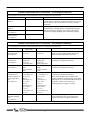
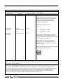
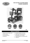
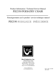
Installation
Operation
Maintenance
Troubleshooting
Version 1.1, Apr/11
Biscayne Fixed Base
Dear Customer
Product Description
Classifications
General Data
Technical Specifications
Technical Specifications and Product Label
Transportation and Storage Conditions
Product Symbols
Packing Symbols
Dimensions
Installation
Special Care for Installation
Fixing the Chair to the Floor
Operation
Foot Control
Headrest
Overcurrent Protection
Maintenance
Recommendations for the Dental Equipment Maintenance & Operation
Replacing the Fuse
Cleaning the Equipment
Precautions
Troubleshooting
Warranty
Final Considerations
2
3
3
4
8
9
9
9
10
10
11
12
12
12
13
13
13
13
14
14
14
15
15
16
17
18
Congratulations! All of us at Summit Dental Systems want you to know that your Biscayne Fixed Base
Chair has been built with the finest materials available. The assembly and testing was completed by technicians
devoted to making Summit Dental Systems products perform to all prescribed specifications. Our five year limited
warranty is just one of the ways we express our confidence that you will be completely satisfied with your purchase.
We appreciate your support and look forward to meeting your future professional needs through our expanding
product line.
This manual is a general presentation of your product and it will give you important details to help you solve
possible problems. Please read this manual thoroughly and keep it for future reference.
The Biscayne Fixed Base Chair was designed for the seating of patients during dental treatments. It
features automatic up and down movements of the backrest powered by a DC motor. The chair has an innovative
and modern round-edged design that includes a curved backrest that provides patients with ultimate comfort and
allows for the best working position for the professional.
The chair is ambidextrous and available with optional fixed armrests. The round-edged fixed armrests are
designed to facilitate patient access and improve the professional’s productivity by avoiding unnecessary
movements and making cleaning much easier. The headrest is removable and height adjustable. The seat and
backrest both come with ample padding and lumbar support, mounted on a rigid frame and covered with injected
high-resistance polyurethane, and coated with laminated material that is seamless, non-toxic and non-flammable.
The chair has a steel-built structure with a resistant, smooth, high-shine, round-edged coating. It is coated
in smooth epoxy coating, polymerized at 482ºF (250ºC), with a phosphate process resistant to rust and cleaning
products. The base is ergonomically designed and has 4 holes that allow for securing the dental chair to the floor.
IMPORTANT:
• This equipment is for professional use only. It must be operated and utilized by a specialized professional
(certified professional, according to the legislation of the country) and following the instructions of the manual.
• It is the user’s responsibility to only use this equipment if it is in good working condition to protect themselves,
the patients, and others from dangerous situations.
• This equipment should not be used in the presence of inflammable anesthetics or products that may cause an
explosion.
• After the equipment has completed its life-cycle, this equipment must be disposed of in an appropriate area
(according to the legislation of the country).
• To guarantee the safe functioning of your equipment, use only the Summit Dental Systems assembly
configurations (Dental Chair, Delivery Units, Assistant’s Instrumentation, and Dental Light) supplied by Summit
Dental Systems authorized Dealers/Technical Assistance.
3
According to the type of protection against electric shock: CLASS I.
According to the mode of operation: CONTINUOUS DUTY.
According to the degree of protection against electric shock: TYPE B EQUIPMENT.
According to the degree of protection against ingress of water: ORDINARY (IPX0) PROTECTION.
According to the degree of safety of application in the presence of a flammable anesthetic mixture with air,
oxygen, or nitrous oxide: EQUIPMENT NOT SUITABLE FOR USE IN THE PRESENCE OF A
FLAMMABLE ANAESTHETIC MIXTURE WITH AIR, OR WITH OXYGEN, OR NITROUS OXIDE.
4
Guidance and manufacturer’s declaration – electromagnetic emissions
The Biscayne Fixed Base Chair is intended for use in the electromagnetic environment specified below. The customer or the
user of the Biscayne Fixed Base Chair should assure that it is used in such an environment.
EMISSION TEST
COMPLIANCE
RF Emissions
CISPR 11
Group 1
RF Emissions
CISPR 11
Harmonic Emissions
IEC 61000-3-2
Voltage Fluctuations/
flicker emissions
IEC 61000-3-3
Class B
Class A
ELECTROMAGNETIC ENVIRONMENT GUIDANCE
The Biscayne Fixed Base Chair uses RF energy only for its
internal function. Therefore, its RF emissions are very low and
are not likely to cause any interference in nearby electronic
equipment.
The Biscayne Fixed Base Chair is suitable for use in all
establishments, including domestic establishments and those
directly connected to the public low-voltage power supply
network that supplies buildings used for domestic purposes.
Complies
Guidance and manufacturer’s declaration – electromagnetic immunity
The Biscayne Fixed Base Chair is intended for use in the electromagnetic environment specified below. The customer or the
user of the Biscayne Fixed Base Chair should assure that it is used in such an environment.
IMMUNITY TEST
IEC 60601
TEST LEVEL
COMPLIANCE LEVEL
ELECTROMAGNETIC ENVIRONMENT GUIDANCE
Electrostatic
Discharge (ESD)
IEC 61000-4-2
± 6 kV contact
± 8 kV air
± 6 kV contact
± 8 kV air
Floors should be wood, concrete or ceramic tile. If
floors are covered with synthetic material, the
relative humidity should be at least 30%.
Electrical fast
transient/burst
IEC 61000-4-4
± 2 kV for power
supply lines
± 1 kV for
input/output lines
± 1 kV differential
mode
± 2 kV common
mode
< 5% UT
(> 95% dip in UT)
for 0,5 cycle
40% UT
(60% dip in UT)
for 5 cycles
70% UT
(30% dip in UT)
for 25 cycles
< 5% UT
(> 95% dip in UT)
for 5 sec
3 A/m
± 2 kV for power
supply lines
± 1 kV for
input/output lines
± 1 kV differential
mode
± 2 kV common
mode
< 5% UT
(> 95% dip in UT)
for 0,5 cycle
40% UT
(60% dip in UT)
for 5 cycles
70% UT
(30% dip in UT)
for 25 cycles
< 5% UT
(> 95% dip in UT)
for 5 sec
3 A/m
Main power quality should be that of a typical
commercial or hospital environment.
Surge
IEC 61000-4-5
Voltage dips, short
interruptions and
voltage variations on
power supply input
lines
IEC 61000-4-11
Power frequency
(50/60 Hz) magnetic
field
IEC 61000-4-8
NOTE: UT is the a.c. mains voltage prior to application of that test level.
5
Main power quality should be that of a typical
commercial or hospital environment.
Main power quality should be that of a typical
commercial or hospital environment.
If the user of the Biscayne Fixed Base Chair
requires continued operation during power mains
interruptions, it is recommended that the Biscayne
Fixed Base Chair be powered from an
uninterrupted power supply or a battery.
Power frequency magnetic fields should be at
levels characteristic of a typical location in a
typical commercial or hospital environment.
Guidance and manufacturer’s declaration – electromagnetic immunity
The Biscayne Fixed Base Chair is intended for use in the electromagnetic environment specified below. The customer or the
user of the Biscayne Fixed Base Chair should assure that it is used in such an environment.
IMMUNITY TEST
IEC 60601
TEST LEVEL
COMPLIANCE LEVEL
ELECTROMAGNETIC ENVIRONMENT GUIDANCE
Portable and mobile RF communications
equipment should be used no closer to any part of
the Biscayne Fixed Base Chair, including cables,
than the recommended separation distance
calculated from equation applicable to the
frequency of the transmitter.
Recommended separation distance
d = 1.2 √P
Conducted RF
IEC 61000-4-6
Radiated RF
IEC 61000-4-3
3 Vrms
150 kHz to 80 MHz
3 V/m
80 MHz to 2.5 GHz
3 Vrms
d = 1.2 √P 80 MHz to 800 MHz
d = 2.3 √P 800 MHz to 2.5 GHz
3 V/m
where P is the maximum output power rating of
the transmitter in watts (W) according to the
transmitter manufacturer and d is the recommended
separation distance in meters (m).
Field strengths from fixed RF transmitters as
determined by an electromagnetic site surveya
should be less than the compliance level in each
frequency rangeb.
Interference may occur in the vicinity of equipment
marked with the following symbol
NOTE 1: At 80 MHz and 800 MHz, the higher frequency range applies.
NOTE 2: These guidelines may not apply in all situations. Electromagnetic propagation is affected by absorption and reflection
from structures, objects and peoples.
a
Fields strengths from fixed transmitters, such as base stations for radio (cellular/cordless) telephones and land mobile radios,
amateurs radio, AM and FM radio broadcast and TV broadcast cannot be predicted theoretically with accuracy. To access the
electromagnetic environment due to fixed RF transmitters, an electromagnetic site survey should be considered. If the
measured field strength in the location in which the Biscayne Fixed Base Chair is used exceeds the applicable RF compliance
level above, the Biscayne Fixed Base Chair should be observed to verify normal operation. If abnormal performance is
observed, additional measures may be necessary, such as re-orienting or relocating the Biscayne Fixed Base Chair.
b
Over the frequency range 150 kHz to 80 MHz, field strengths should be less than 3 V/m.
6
Recommended separation distance between
portable and mobile RF communications equipment and the Biscayne Fixed Base Chair
The Biscayne Fixed Base Chair is intended for use in the electromagnetic environment in which radiated RF disturbances are
controlled. The customer or the user of the Biscayne Fixed Base Chair can help prevent electromagnetic interference by
maintaining a minimum distance between portable and mobile RF communications equipment (transmitters) and the Biscayne
Fixed Base Chair as recommended below, according to the maximum output power of the communications equipment.
SEPARATION DISTANCE ACCORDING TO FREQUENCY OF TRANSMITTER
m
RATED MAXIMUM OUTPUT
POWER OF TRANSMITTER
W
150 kHz to 80 MHz
d = 1.2 √P
80 MHz to 800 MHz
d = 1.2 √P
800 MHz to 2,5 GHz
d = 2.3 √P
0.01
0.12
0.12
0.23
0.1
0.38
0.38
0.73
1
1.2
1.2
2.3
10
3.8
3.8
7.3
100
12
12
23
For transmitters rated at a maximum output power not listed above, the recommended separation distance d in meters (m) can
be estimated using the equation applicable to the frequency of the transmitter, where P is the maximum output power rating of
the transmitter in watts (W) according to the transmitter manufacturer.
NOTE 1: At 80 MHz and 800 MHz, the separation distance for the higher frequency range applies.
NOTE 2: These guidelines may not apply in all situations. Electromagnetic propagation is affected by absorption and reflection
from structures, objects and people.
7
Biscayne Fixed Base Chair
Optional Items:
ATTENTION: The equipment
must be used only with the
power cable provided by Summit
Dental Systems.
A
01) Headrest
02) Double Articulating Headrest
03) Backrest
04) Armrest
05) Fuse
06) Manual Height Adjustment Knob
07) Base
08) Seat
09) Power Cable Socket
10) On/Off Switch
11) Up/Down Button for Backrest
8
Optional Items
A) Fixed Armrests
Nominal Tension
Frequency
Consumption
Power
115V~/220V~
50Hz/60Hz
1.3A
200VA
• Supply voltage: 115V~ / 220V~
• Frequency: 50 Hz / 60 Hz
• Electric shock protection type:
Class one equipment.
• Intermittent Operation:
T-on 1min. - T-off 4min.
• Water leak protection:
IPX0
• Power: 1.3 A
• Net Weight: 190lb (86Kg)
• Gross Weight: 216lb (98Kg)
Transportation and Storage Conditions
The equipment must be transported and stored with the following observations:
-
Fragile! Should not suffer drop or receive impact.
With the arrows pointing upward.
With humidity protection, not to be exposed to rain, water drops, or wet floor.
In temperatures from 10.4 ºF (-12ºC) to 122 ºF (50ºC).
Maximum stacking indicates on the packaging the number of boxes that can be stacked during the
transportation and storage.
9
Product Symbols
Raises backrest
Lowers backrest
Protective Grounding Point
Type B equipment
Warning: Consult the manual
NOTE: Class I Equipment
Packing Symbols
The equipment must be protected
from exposure to direct sun light
during storage and transportation.
Temperature limit for storing and
transportation of package.
Equipment can’t get wet, rained on,
or placed on a wet floor during
transportation or storage.
Maximum stacking determines the
maximum number of boxes which
can be stacked during transportation
and storage.
Package to be transported and
stored with the arrows pointing up.
Package to be transported and
stored with care (Fragile! Should not
suffer drops or receive impact).
10
Dimensions
Biscayne Fixed Base Dental Chair
MIN 61” │1549mm
MAX 77”│1956mm
MIN 19.5”│495mm
MAX 26.5”│673mm
25”│635mm
MIN 42.5”│1080mm
MAX 50”│1270mm
MIN 13”│330.2mm
MAX 20”│508mm
11
26”│660mm
21”│533mm
16.5”│419mm
9”│229mm
23.5”│597mm
24”│610mm
The installation for this equipment requires the assistance of a specialized technician authorized by
Summit Dental Systems.
The height adjustment of the chair’s base is performed manually by adjusting the knob. This
adjustment should only be performed by a specialized technician authorized by Summit Dental
Systems.
-
-
This equipment should only be installed by a specialized technician authorized by Summit Dental Systems,
and not doing so could result in loss of warranty, for only he possesses the information, tools, and training
necessary to complete the task.
Summit Dental Systems is not responsible for damages or accidents caused by poor installation performed
by a technician that is not authorized by Summit Dental Systems.
Equipment is only ready for operational use after being properly installed and tested by a specialized
technician authorized by Summit Dental Systems.
Special Care for Installation
-
Check the electric net, it must be compatible with the specified one in the equipment.
Install the equipment in an adequate location, protected from solar rays and humidity.
Verify that the outlet is grounded; it must be turned off correctly.
Verify that the master switch of the equipment is at the position “0”.
ATTENTION: This equipment should only be used with the power cord supplied by Summit Dental
Systems, otherwise it may increase emissions or decrease the immunity of the equipment.
When moving the chair, never lift it by the seat (where the patient’s leg support is), lift it by the base of the
structure.
How to fix the dental chair base to the floor:
This chair must be fixed to the floor with the use
of four bolts and bushings that are provided with the
equipment. Mark the floor, drill with 10mm drill, fitting the
four S10 bushings into the holes. Position the seat
aligned with the holes and secure it using the four 5/16” x
60mm hex head steel bolts and bushings. The holes are
located under the base plate’s plastic cover.
12
Operation of the Backrest
17 - Raise backrest
18 - Lower backrest
Double Articulated Headrest
To move the headrest, turn
knob (12) counterclockwise until
headrest is loose. Adjust the
headrest to the desired position and
then tighten the knob back by
turning it clockwise.
To adjust height, just move
it vertically.
Overcurrent Protection
This chair is equipped with a safety device for overcurrent through two 5 amp fuses and internal
overcurrent protection for the equipment mounted to the chair.
13
Recommendations for the Dental Equipment Maintenance and Operation
Your Summit Dental Systems equipment has been designed and developed according to the standards of
modern technology. Similar to other kinds of equipment, it requires special care, which is many times neglected due
to several reasons and circumstances.
Therefore, here are some important reminders for your daily routine. Try to follow these simple rules, which
will save you a lot of time and will avoid unnecessary expenses once they become a part of your working
procedures.
-
The equipment should only be operated by properly qualified and trained technicians and dental
professionals.
If the need of maintenance occurs, use only the service of a Summit Dental Systems authorized
dealer/technician.
Do not expose plastic components into contact with chemical used in routine dental treatment such as:
acids, mercury, acrylic liquids, amalgams, etc.
Switch off the equipment when not in use for a prolonged amount of time.
Always keep the equipment clean before next the procedure.
Do not modify any part of the equipment. Do not disconnect the cable or any other connections without
necessity.
Summit Dental Systems will not be responsible for:
- Use of the equipment other than that for which it is intended.
- Damage caused to equipment, professional, or patients due to improper installation procedures, faulty
maintenance, and incorrect operation that is contrary to the correct use as described in this user’s manual.
Replacing the Fuse
With the aid of a screwdriver, loosen the fuse
holder cover (16) and then replace the fuse (14)
with the spare fuse (15).
Note: The spare fuse (15) comes with the
equipment. After making the first change, it is
advisable that there always be a spare fuse (5) (see
page 08).
Sensitivity to Environmental Conditions During Normal Use
The equipment was designed to not be sensitive to interference such as magnetic fields, external
electrical influences, electrostatic discharge, pressure or pressure variations, provided that the equipment is
installed, kept clean, maintained, transported, and operated in accordance with this user’s manual.
14
Cleaning the Equipment
Disinfect between each use:
-
Before cleaning the equipment, turn the chair’s power switch off.
Avoid spilling water or other liquids inside the equipment that could cause short circuits.
Do not use abrasive materials or steel wool for cleaning; do not use organic solvents or detergents that
contain solvents such as ether, stain removers, gasoline, etc.
Because there are hundreds of cleaners, conditioners and disinfectants available, it is impossible for
manufacturers to test them all. The manufacturer of the cleaner or disinfectant to be used should be contacted for
them to state whether or not the disinfectant will damage equipment surfaces including upholstery. A solution of
mild non-ionic detergent and water is recommended for routine surface cleaning. Never use abrasives.
Unacceptable Disinfectants
The following chemicals may damage equipment and upholstery:
Alcohol based solutions
Acetone
Bleach
Phenol
Foam spray products
Certify the correct voltage when you plug in your equipment.
Install your equipment in a proper place protected from solar rays and humidity.
When moving the chair, never lift it by the seat (where the patient’s leg support is); lift it by the base of
the structure.
The plastic parts can’t be in contact with most chemical substances used in dentistry treatments (i.e.
acids, mercury, acrylic liquids, amalgams, etc).
Whenever equipment is not in use, turn the chair’s power switch to off.
15
In case of an abnormality, check to see if the problem is related to any of the items listed in
Troubleshooting. If you cannot solve the problem, disconnect the power cord from the power outlet and contact
your Summit Dental Systems authorized dealer/technician.
Problem
-
Chair is not working
Probable Cause
-
Plug is disconnected from
socket
Power is cut
Main switch is off
Burned fuse(s)
Solution
-
Connect plug to socket
-
Wait until power is back
Switch the main switch on
Replace fuse(s)
ATTENTION: Any other problem that could happen with this equipment should only be repaired by a Summit
Dental Systems authorized technician. Any misuse, negligence or maintenance not performed by a Summit Dental
Systems authorized technician will result in the loss of the warranty.
16
Summit Dental Systems (SDS) warrants its products against defects in materials or workmanship from the date of
shipment to the Buyer as follows:
Summit Dental Systems (SDS) Equipment:
Chairs, Delivery Units, Cuspidors, Lights
Zipclave Sterilizer
Control Block Diaphragm (part of Delivery Unit)
All Upholstery, Stools, All Plastic Covers, and Cabinets
Zipclave Heating Element & Zipclave Gasket
Warranty Period:
5 Years
3 Years Limited Parts
Lifetime
1 Year
1 Year
Summit Dental Systems’ sole obligation under the warranty is to provide parts for repair, or at its option, to provide a
replacement product (excluding all labor and shipping fees). “In any action, BUYER’S remedies are limited to the
warranty described above. BUYER shall not be permitted to claim lost profits, reliance, special, incidental, or
consequential damages in any proceedings.” The warranty does not cover damage from improper installation or
maintenance, accident or misuse. The warranty does not cover damage resulting from the use of cleaning
disinfecting or sterilization chemicals and processes. Failure to follow instructions provided in Summit Dental
Systems’ Operation and Installation Manuals (Owner’s Guides) may void the warranty. In the event Warranty
service must be performed to correct any defect, only an authorized Summit Dental System dealer may perform any
and all warranty repairs. Any repairs by unauthorized dealers, technicians, or repairmen may void the warranty.
of aa defective
defective warranty
warranty item, a copy of the replacement
replacement invoice,
invoice, model and serial number of the
In the case
case of
serial
number
of
the
product
under
which
it
was
replaced,
and
a
description
of
product under which it was replaced, and a description of symptoms of the defect
must be returned with the part
symptoms
of
the
defect
must
be
returned
with
the
part
within
30
days
of
the
within 30 days of the replacement invoice date to Summit Dental Systems,
6277 NW 28th Way, Ft. Lauderdale,
th
replacement invoice date to Summit Dental Systems, 6277 NW 28 Way, Ft.
FL 33309, USA, in order to receive credit. Any and all expenses for freight, labor to perform warranty service,
Lauderdale, FL 33309, USA, in order to receive credit. Any and all expenses for freight,
and
purchase of spare parts are the responsibility of the buyer. Any fraudulent claims made may void the
labor to perform warranty service, and purchase of spare parts are the responsibility of
warranty.
that may
provided
by an authorized
Summit
Dental Systems dealer is the
the buyer.Any
Anyadditional
fraudulentwarranty
claims made
may be
void
the warranty.
Any additional
warranty
sole
responsibility
of
said
dealer.
that may be provided by an authorized Summit Dental Systems dealer is the sole
responsibility of said dealer.
SDS reserves the right to make changes or improvements on any products without being required
SDS
reserves
the right
to make
or improvements on any products without
to modify
existing
equipment
inchanges
a like manner.
being required to modify existing equipment in a like manner.
Please complete and retain for your records the following Information:
In case of warranty part replacement/repair or when ordering a part, please call your authorized Summit Dental
Systems dealer and have the following information available:
Owners’ Name:
Phone #:
Model #:
SDS Serial #:
Dealer:
Phone:
Purchase Date:
17
The most important aspect related to equipment care is that concerning spare parts. To guarantee the
maximum life span of your equipment, use only original Summit Dental Systems spare parts. They are sure to
follow the technical specifications and standards required by Summit Dental Systems.
We must also point out to you our network of authorized dealers. Only dealers within this network will be
able to keep your equipment well maintained for they count on technical assistants who have been trained and
possess specific tools for the correct maintenance of your equipment.
Questions and Information: Summit Dental Systems Call Center 1-800-275-3368.
18
MT Promedt Consulting GmbH
Altenhofstrasse 80
D-66386 St. Ingbert, Germany
1
6277 NW 28th Way – Ft. Lauderdale, FL 33309 Phone: (800) 275-3368 www.summitdental.com