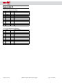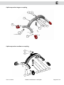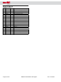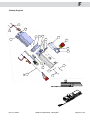
1
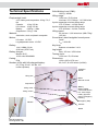
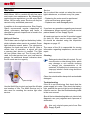
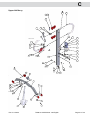
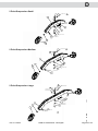
Technical manual Molift Mover 180 Etac AS Etac Supply Gjøvik Hadelandveien 2 N - 2816 Gjøvik TM08101 Molift MOVER 180 English - Rev. A 10/2012 Page 2 of 32 TM08101 Molift Mover 180 English Rev. A 10/2012 Table of contents Appendix B............................................................ 18 General Advice....................................................... 5 Chassis and Legs, Mover 180...................... 19 Explanation of Symbols................................... 5 Safety Precautions........................................... 5 Disclaimer. ........................................................ 5 Appendix C............................................................ 20 Technical Description.......................................... 6 Upper contact assy 340 ............................... 23 Upper contact assy 440. ............................... 23 Main Components............................................ 6 Chassis and Legs. ........................................... 6 Column and Battery Holder............................ 6 Electronics...................................................... 6 Battery............................................................ 6 Arm and Suspension....................................... 6 Hand Control Unit. ........................................... 6 Charger and Battery. ....................................... 6 Technical Specifications.................................... 7 Service....................................................................... 8 Notice of Service.............................................. 8 Service .......................................................... 8 Cleaning. ........................................................... 8 Troubleshooting................................................ 8 Repair......................................................................... 9 Replacing Motor............................................... 9 Disassembly of arm......................................... 9 Disassembly of Column. ............................... 10 Replacing chassis parts................................ 10 Disassembly of Leg Parting Motor............... 10 Assembly of Leg Parting Motor.....................11 Wheels..............................................................11 Back Wheel...................................................11 Front Wheel.................................................. 12 Control Card. .................................................. 12 Replacing Emergency Stop Switch.............. 12 Mounting of Control Card............................. 13 Marking............................................................ 13 Upper Half Assy. ............................................ 21 Appendix D............................................................ 22 Appendix E. ........................................................... 24 4 pkt suspension large w coupling............... 25 4 pkt suspension medium w coupling......... 25 Appendix F............................................................. 26 Battery Support. ............................................. 27 Appendix G............................................................ 28 Scale Set......................................................... 29 Appendix H............................................................ 30 IMPORTANT! Electrical diagram. ......................................... 31 The patient lifter is only meant to be used by qualified personnel. The manual shall not be handed over, or made available to, any unauthorised third party, without a prior written consent from Etac Supply Gjøvik. Existing laws, conventions and agreements protects all documents. No extract of this documentation can be reproduced, used or transferred without prior written consent from Etac Supply Gjøvik. Violation of these regulations may lead to judicial repercussions and economic responsibility. Industrial rights are reserved. Final Revision....................................................... 14 Testing. ............................................................ 14 Logging............................................................ 14 Inspection Diagram after Service and Repair............................................................................ 15 Appendix A. ........................................................... 16 Main Components...........................................17 Rev. A 10/2012 Etac AS, Etac Supply Gjøvik Hadelandsveien 2 2816 Gjøvik, Norway Teleph: (+47) 40001004 Fax: (+47) 40001008 TM08101 Molift Mover 180 English www.molift.com [email protected] Page 3 of 32 Page 4 of 32 TM08101 Molift Mover 180 English Rev. A 10/2012 General Advice Disclaimer Etac Supply Gjøvik does not accept This technical manual contains important responsibility for damages and functional faults information about the lift, including safety if the instructions in the manual have not been precautions. Study the manual carefully before followed. Claims covered by the warranty should be made immediately after a deficiency handling and repairing the patient lift. has been discovered, and marked with the serial number of the lift and any identification Explanation of Symbols 1 A Refers to Appendix A, Position 1. on figure. number to the service personnel. Normal wear is not covered by the warranty. This symbol appears in the manual All technical information, data and instructions next to information related to workplace in this manual was completely up-to-date at safety, and when a potential risk for injury the time this manual was sent for printing. to personell may accur. Always follow all The manual was compiled on the basis of these instructions and be extra observant our experience and to the best of our ability and intentions. We reserve the right to make and careful. technical modifications in connection with This symbol refers to important further development and improvement of information about the correct use of the the product described in this manual. Claims equipment described in this manual. may therefore not be based on information, Failure to take notice of the information illustrations and descriptions contained in this may lead to functional faults or damages manual. We do not take responsibility for any kind to the equipment. of damages and faults wich occurs from This symbol highlights information, unintended use related to failure to follow which is especially useful. If instructions the manual or insufficient maintenance. We are followed, you may be able to use want to emphasize that only Molift spare the equipment more efficiently. The parts and equipment approved by us may be information simplifies work tasks or used. For safety reasons, the installation and use explains complicated facts. of unapproved spare parts or equipment, and unauthorised modification and alteration of the Safety Precautions Repair of the lift involves lifting and handling product is not allowed. Etac Supply Gjøvik does objects, which are heavy, long and/or sharp. not accept responsibility for damages caused Assembly or disassembly of parts may affect by such. the stability of the lift, and this creates a risk that With the exception of indirect damages, Etac Supply Gjøvik takes responsibility for faults and it may topple over or collapse. deficiencies of the product within the scope of Read the operator manual and follow what is described in the purchase agreement. Claims for damages are excepted, regardless general safety precautions. of whatever legal foundation such claims may be based on. Only the documentation related to the product is valid. If safety directions or other regulations described in this manual have not been followed, the conformity declaration (CE declaration), delivered with this product in accordance with the Directions for Medical Equipment (93/42/ EØF), is considered invalid. Rev. A 10/2012 TM08101 Molift Mover 180 English Page 5 of 32 Technical Description Main Components The lift is delivered in three main parts: 1. Chassis with legs. 2. Lifting arm and column with battery holder and electronics. 3. Suspension. Chassis and Legs The chassis B 1 is made of steel. The adjustable legs are made from aluminium profiles and are attached to the chassis with a leg parting mechanism and a motor B 11 . Column and Battery Holder The column C 3 , placed in the holder on the chassis B 1 , is an aluminium profile. There is an operation handle and a battery holder on the column. The battery holder contains all the electronics and the control card. Arm and Suspension The lifting arm C 1 and suspension A 3 are of aluminium. The lifting arm is suspended on the column. A motor C 7 operates the lifting arm. The suspension A 3 has 2 or 4 safety hooks for the sling. The coupling has a locking pin to make suspension susbstitution easy. Hand Control Unit The hand control A 5 has four buttons for lift operation; ”up”, ”down”, ”legs out” and ”legs in”. A light indicates when the battery needs charging. The remote control socket is located at the bottom of the battery holder. Charger and Battery Molift Mover 180 runs on a battery consisting of a 14,4 V battery pack A 4 . The Battery is charged in a table top charger A 6 or with an integrated charger on the lift. With table top charger one battery can be charged while another operates the lift. The lifting arm C 1 is suspended at the top of the column and can be raised and lowered. Electronics The electronics consists of a PCB (printed circuit board) F 5 with remote control, emergency stop and emergency lowering, battery and service lights. All functions rely on the control card. The control card has a counter, which registers the number of seconds with activity. After a certain time, it signals to activate the service light to inform the user that the lift needs service. An electric emergency lowering switch E 14 is located above the stop switch. In case of power failure the electric emergency lowering will not work and the manual emergency function on lifting motor C 7 must be used. Battery The battery A 4 is placed in the battery holder and consists of 12-cell NiMH battery pack. Page 6 of 32 TM08101 Molift Mover 180 English Rev. A 10/2012 Technical Specifications excl. battery and suspension: 32 kg / 70,5 lbs Chassis: 16 kg / 35 lbs Lift column: 16 kg / 35 lbs Battery: 0,85 kg / 1,9lbs Suspension: 0,9 kg / 2 lbs Material: Motors: Aluminium, steel and plastic composite Lift motor: 12 VDC Leg adjustment motor: 12 VDC 14.4 V NiMH 2.2 Ah, 20 A fuse (ATO Fuse) Mascot 2215, 10-22 cells NiCd/NiMH IP24 50 (75 kg, 50 cm / 165 lbs, 19,7 inches up/down) Battery: 1360 mm / 53,5 inches min/max: 370-1730mm / 14,5-68 inches 2 point suspension min/max lifting range: 370-1730mm / 14,5-68 inches 4 point suspension min/max lifting range: 270-1630mm / 10,6-64,2 inches Lifting speed: 46 mm/sec / 1,06 inches/sec (With 75kg / 165 lbs) Sound level, max A-weighted sound power level: LWA = 49.4 dB Key force: Buttons on handset: 3.4 N Max. 115 mm / 4,52 inches Leg height: Battery charger: Casing: 180 kg / 400lbs Lifting range: Empty weight, total: Safe Working Load (SWL): Turning circle: 1350 mm / 53,15 inches Dimensions: Number of lifts with fully charged battery: 1250 x 695 x 1270 mm / 49,2 x 27,36 x 50 inches (LxWxH) Lifting arm Operation handle Motor Remote control Suspension Battery Lifting motor Battery holder Control electronics, incl. service light, battery light and electric emergency lowering Lifting column Leg Emergency Stop front Chassis back Manual emergency lowering Mover 180 Rev. A 10/2012 TM08101 Molift Mover 180 English Page 7 of 32 Service Service Service should be carried out when the service light indicates so, or at least every five years. Molift Mover 180 is a mobile lift with few parts and require low maintenance. By following the regular service regulations, you will enjoy Molift • Replacing the motor must be performed when service lamp gives signal. Mover 180 for many years. Service can only be • Replace worn and damaged parts. carried out by authorised personnel. In addition to the required service, Etac Supply Gjøvik recommends regular inspections to If you have any questions regarding service and detect unforeseen damages and faults. A maintenance, please contact your local service checklist for periodic inspections is found in the partner/dealer or Etac Supply Gjøvik. User Manual. All repair and service on the lift must be logged for each lift. After service and/or repair, the Notice of Service The lift has a service light on the battery holder, lift should be checked using the Inspection which indicates when service is needed. Green diagram on page 15. light indicates normal status. The electronics registers the loads and use of the lift. After a The owner of the lift is responsible for storing certain time of operation, a signal will give information regarding inspections, service and a warning that service is needed. The light repair. will turn yellow, then red. The lift may still be used, but order service from your local service Cleaning partner. An additional buzzer indicates when the lift needs service urgently. Detergents should be pH-neutral. Do not use solvents or other strong fluids, which may damage or ruin outside surfaces or change the characteristics of lift materials. If disinfection is necessary, use isopropyl alcohol. Avoid using abrasives and corrosives. Clean the outside with a damp cloth and suitable detergent. Service light Troubleshooting If the lift is not functioning, first check that the Use the Molift Service tool and read the lift data power supply is in order. Then check the battery and number of lifts. The Molift Service tool is light, and that the service light is not indicating a also used for resetting the service light after need for service. See the troubleshooting table in the user manual. service. Should the troubleshooting table not yield a fault diagnosis, use your judgment and a process of elimination. Use only original spare parts from Etac Supply Gjøvik. Page 8 of 32 TM08101 Molift Mover 180 English Rev. A 10/2012 Repair Remove the battery before maintenance to makes sure the lift does not move unintentionally. Replacing Motor You will need: • Loctite 243 or similar • Special tool, Allen key x 2 • Hot air gun Procedure • Remove the suspension. • Remove column with lifting arm from chassis and put it on a worktop. • Dismantle connector (27) from column, and unplug both wires for motor. • Remove both allen screws holding battery support (24). This will make it possible to pull motorcable out of the hole in the column. and carefully remove them by press/knock. • Remove the motor and put it down gently. • Install a new motor (7). Be careful to install with motor housing turned the right way. • Mount the bolts. • Use Loctite 243 or similar on the screws and tighten. • Insert motor cable through hole in column behind batteryholder. Connect both wires for motor to connector (27). Refer to Electrical diagram. • Mount both allens screws for battery support (24). The battery support works as a strain relief for the motor cable. Make sure that cable is strain relieved. Disassembly of arm • Remove the suspension. • Remove column with lifting arm from chassis and place it on a worktop. • Disconnect the motor by unscrewing the screw (13) and remove the bolt (4), which holds it to the bracket. Heat the screw/bolt to loosen the Loctite. Limit the heat to as small an area, and as • Remove the handle by drilling out the rivet. Gently knock the handle off the column. low temperature, as possible. • Remove nuts and bolts (14,15) on upper and lower bracket for handle. The motor will be disconnected, and may fall down during the next steps. Secure the motor to prevent this . The parts are loose and may fall apart. 927,6 1185,4 65 F F 44 11 26 10 23 9 24 15 6 30 13 F 43 F Apply Loctite 243 14 25 19 F 4 4 D 11 1 17 8 34 33 17 17 21 2 26 Locktite 2701. 16 5 22 31 29 F 13 Apply Loctite 243 F 46 G 3 17 C 36 F 45 18 E 40 28 F 27 41 20 F 35 Electrical diagram 39 Allen Key Hexagon Socket 5mm TM08101 Molift Mover 180 English Pos. G D 17 2 22 42 37 2 35 34 33 32 31 30 29 28 4 1 1 1 2 1 1 2 Ref EO 104/2012 24.09.2012 TVJ F Ref. EO 71/2012 15.06.2012/TES E Ref EO 58/2012 25.05.2012 TVJ D C Ref EO 47/2012 Added pos 36-40 02.05.2012 TVJ 07.03.2012/ERS TÅB TÅB TÅB B New design 28.10.2011/ERS TÅB A Released for production 14.10.2011/ERS TÅB TÅB 1 Bill of materials: Qty. Description. Designed/Drawn: Date: ESK Drawing name: 15.01.2012 25-002 BOM.xls Dimension/ Draw. no. Projection: Material. 27 26 1 1 25 2 24 23 22 21 1 1 1 1 20 19 18 17 1 1 1 4 16 15 14 13 12 11 10 9 8 7 6 5 4 3 2 8 10 2 2 2 1 2 2 1 1 1 2 2 1 1 Page 9 of 32 Comment. Scale: 1:5 Mover 180, upper half assy 1 Drawing number: Size Push bar slee F 13 36 Loctite 243 4 Panhead Apply • Remove the bolt (44) holding the arm to the column. • Remove special bolt and nut (12,13) • Loosen lower and the upper screw (14) at the column using the Allen Key. • Push both bolts (4), or use a bolt or similar Rev. A 10/2012 Apply Loctite 243 33 12 32 7 F 34 37 18 18 F 43 8 43 38 13 4 F C 24 F 1 Default/Qt 43 Fork bolt Label ID no Label Label Partner Handcontroll buttons Battery suppo Slinglabel Max load 255 label Label Label, Art. N Popmutter Bolt w/head Actuator LA3 (03-150) Column Lifting arm fo Linak LA 34 Replacing chassis parts • Take out the bulb and fork (16,32). Remove Use a punch carefully on the inside to separate the covers (16). Position the legs in centre for best access to chassis parts during disassembly. Disassembly of Column • Remove the lifting arm, drive handles and motor as described in disassembly of lifting arm. • Disconnect and remove connector (27) • Remove battery holder (24). • The column can now be replaced; assembly is done in the opposite order. • Remove column with lifting arm from chassis by removing 2x Allen screws and put it sideways in a safe place. • Place the chassis on a work stand. 14 12 F 44 10 927,6 Disassembly of Leg Parting Motor 13 65 15 6 14 25 1185,4 23 19 F 11 17 26 Locktite 2701. 5 31 29 C 37 F 43 F 8 34 46 G 3 33 17 C 30 13 4 F 38 9 24 Apply Loctite 243 F 45 1 17 2 22 21 16 • Loosen the leg parting motor (11) from the bracket (12) by removing screws (13) and nut (14). F 13 Apply Loctite 243 F 36 4 11 D 43 18 E 28 F 27 41 42 18 External power is needed for running the motor out of the spindle nut. 12 32 7 40 20 Make sure fingers do not get caught when running the leg parting mechanism. F • Remove the leg parting motor wire, and connect external power, 12 V. Motor wire connector has a snap hook. Use flat tip screwdriver or similar to release. • Run the leg parting motor inwards until the spindle is free from its nut. Page 10 of 32 TM08101 Molift Mover 180 English G 35 Electrical diagram 39 Allen Key Hexagon So 1 Pos. Ref EO 104/2012 24.09.2012 TVJ TÅB F Ref. EO 71/2012 15.06.2012/TES TÅB E Ref EO 58/2012 25.05.2012 TVJ D C Ref EO 47/2012 Added pos 36-40 02.05.2012 TVJ 07.03.2012/ERS B New design 28.10.2011/ERS TÅB A Rev. Released for production Description: 14.10.2011/ERS Date/Sign. TÅB Approved: TÅB TÅB Rev. A 10/2012 Bill of materials: Qty. Description. Designed/Drawn: Date: ESK Drawing name: 15.01.2012 25-002 B Dimensio Draw. no Projection: Mover 180, upper ha Molift Mover 180. (2). • Mount the bracket (12) by placing flange into slot. Lift and turn it into place. • Place the motor (11) in the correct position. Connect external power and run the spindle out until it fastens to the spindle nut (centred on the spindle). • Fasten the leg parting motor to the bracket with screw (13) and nut (14). • Connect the power wire to the motor. • Mount column with lifting arm on chassis. • Perform a safety test on the lift. WARNING! Do not run the legs to the end positions as the end stop does not work. • Remove the motor and disconnect external power. • The bracket (7), nut holder (6) with spindle nut (9) can be removed by loosening the screws (2). Heat the screws to loosen. 12 13 11 14 8 B 7 9 28 B 27 6 DETAIL E SCALE 1 : 1 B 26 9 E 6 18 Wheels 1 31 19 26 B Apply Loctite 243 20 Apply Loctite 243 31 15 B Place the lift in a stable horizontal position Remove column and suspension for easy handling. B B 10 B B 25 B B 21 16 B Apply Loctite 243 21 Apply Loctite 243 23 5 Apply Loctite 243 2 3 16 4 B Back Wheel • Loosen the wheel (5). 24 Cardbox 25 Cardbox inlay 22 1 Pos. Bill of materials: Qty. Description. Designed/Drawn: Date: ERS 14/03-2012 25-048 BOM.xls Dimension/ Draw. no. Projection: Chassis assy • The bracket (12) is removed by turning it Molift Mover 180 until the pin goes into the slot, and then gently pulling it out. Drawing name: B A Rev. Ref. EO 71/2012 Released for production Description: 14.06.2012/TES 14/03-2012/ERS Date/Sign. TÅB Approved: Material. Comment. 1:5 Scale: 25-048 Drawing number: Size A2 5 12 • Assembly is done in the opposite order. Use Loctite 2701 on the bolt on the wheel. Assembly of Leg Parting Motor • Mount spindle nut (9) and nut holder (6) to bracket (7). Put Loctite 241 on the screws Rev. A 10/2012 TM08101 Molift Mover 180 English Page 11 of 32 D 17 18 Front Wheel D • Special tool is required to remove nut (7). Use heat to loosen the special nut from wheel (5). A • Use Loctite 241 on the screw of the new wheel and mount it. 13 2 C 1 11 3 5 6 7 16 9 15 1 SECTION A-A 12 7 8 8 9 9 B 14 3 4 4 Apply Loctite 243 B 19 6 5 6 1 5 Pos. Control Card Qty. Description. Designed/Drawn: Date: ERS Drawing name: A Rev. • • • • • Bill of materials: 14/03-2012 4 3 9 1 2 Ref EO 58/2012 • Gently pull out the control card and loosen Pos. Qty. wires (5). 25-049 BOM.xls B A Rev. C B 8 7 2 10 A 09101 vinkel PAF2 2 23x11 1 03-10 Pos. 11203 2 washe 1 hjul 75mm 09201 09202 2 ø4,8x1 Designed 1 03-10 TV 2 AV 02711 00824 Drawing 14101n 1 Leg profile 25-05 125.05.2012 Flat 6x78x TVJbar left 10 Dimension/ Draw. no. Projection: Material. Scale: Released for production Description: Watch the extensions for the emergency lowering switch. 1:10 Ref EO 104/2012 Added 1x pos 9 25.09.2012 TVJ 15.05.2012 TÅB TÅB TES 14.03.2012/ERS Date/Sign. TÅB Approved: Page 12 of 32 Drawing number: TM08101 Molift Mover 180 English Size Rev. A 10/2012 TÅB Approved: Description Comment. The control card may only replaced Replacing Emergency Stop Switch Legbe profile L assy if all the data can be copied over from • Loosen the emergency stop switch from the A3 Mover 180 25-049 the old card to the new one. If copying is inside. Watch the extension, end piece and impossible, the lift should be sent to Etac nut. Supply Gjøvik. • Pull out the emergency stop switch. • Mount a new emergency stop switch and secure it with the nut. Copy the data from the card using the Molift • Make sure the extension, end piece and Service tool. Connect lift and copy to PC. washer are correctly placed on the card in Connect the new control card and copy from relation to the switch. PC to card according to the instruction. Remove battery and lifting arm with suspension and place the column on a worktop. Loosen connector C 27 and disconnect wires. Remove both screws C 26 and dismantle battery holder with wires from column. Loosen membranes (6) and open battery holder by loosening screw (10) and removing the upper and middle part. Released for production Description: Bat 04.05.2012 TVJ Date/Sign. Mol Dimen Draw. Mounting of Control Card • Remove the piece of paper on the card’s buzzer before mounting the card. • Connect all wires and place the card in the battery holder. Check that all LED are positioned in the LED guides. correctly • Mount the extensions for the emergency lowering switch. • Put the upper part of the battery holder into place. • Place battery in the holder and check light/ buzz. • Place a new membrane on the battery holder. • Mount column with lifting arm on chassis. • Perform a safety test on the lift. Marking Check all markings/stickers - replace any damaged markings/stickers. Rev. A 10/2012 TM08101 Molift Mover 180 English Page 13 of 32 Final Revision Logging This diagram is for logging of service, repairs and correcting damages. Each lift should have Testing After any service, repair or replacement, a a diagram for logging of all work done on the lift. safety test should be made according to the The owner of the lift is responsible for storing this diagram. Service technicians should sign inspection diagram. any work done. Owner: Date Description of work completed Page 14 of 32 Molift Mover 180, serial number: Sign./Cert. no. TM08101 Molift Mover 180 English Rev. A 10/2012 Inspection Diagram after Service and Repair Molift Mover 180 The lift has been visually checked for damages, faulty function and deformation, and it is in order. Checked that the suspension has no cracks or other damages. The lift has no loose parts, and correct mounting. The column is locked with both allen screws to chassis. Remote control works. Wire and socket for remote control are undamaged. Suspension can easily be disassembled / assembled. Lift run all the way up and down several times without load. Lift functions are in working order without abnormal noise. End stop works. Test repeated with a load of around 100 kg. Leg parting mechanism run all the way in and out several times without load. End stop works and legs travels easy both ways. Test repeated with a load of 100 kg. Emergency stop and lowering (electric and manual) checked and working. Battery light is green and there are no lights on service lamp. Marked lift with safety sticker with month/year and certificate number for completed safety inspection. Inspecting person must sign safety sticker and this diagram. During service: Used the Molift Service tool and read the lift data and noted number of lifts. NB!: Write down ”Sum” from right-hand column. This shows total number of lifts (equiv. to class 2 lift/15 sec) and remaining lifts until next service. NB!: The service light must ONLY be reset after completed service! No. of lifts (Sum):________________________ Service completed: _______________________________ Service is completed (always when service light is on): - Replaced the suspension. Replaced lifting motor. Checked visually for damages. Worn, damaged or malfunctioning parts, are replaced. See description for parts replacement. Use the Molift Service tool and read the lift status and service data. Completed safety inspection after service. Service light was reset using Molift Service tool. NB!: The service light must ONLY be reset after completed service! Inspection, repair and service should be done by a person certified by, or on behalf of Etac Supply Gjøvik. Client:________________________________ Serial number of lift:___________________________ Date: ________________________________ Signature:___________________________________ Rev. A 10/2012 TM08101 Molift Mover 180 English Page 15 of 32 Appendix A Pos. Item no. Qty. Description Molift Mover 180 1 18200001 1 Chassis assy 2 1810001 1 Coloumn assy 3 1830001 2 2-pt suspension Large 1830002 2-pt suspension Medium 1830003 2-pt suspension Small 1830011 4-pt suspension Medium 1830010 4-pt suspension Large 4 0541000 1 Battery 14,4 V NiMH PowerPac 5 2018004 1 Hand Control 4 Buttons 6 1340100 1 Battery Charger Page 16 of 32 TM08101 Molift Mover 180 English Rev. A 10/2012 A Main Components 10 6 A v. Re B C D 11 Re m Ad ov de ed dp po os s. 1 A . d Re 4 1 de 3a lea d nd se d fo sprin 14 gs rp De rod sc rip uc tio tio n: n 14 .03 11 .20 .03 08 .20 08 09 .05 RV S .20 06 05 .0 Da 5.20 05 te/ Sig n. Po s. M HL L MH MH L MH Ap L pro ve d: De s win Dra 13 12 11 1 9 4 La 6 1 bel Ch 4 1 a r La ger 3 4 b mo Lig el Ba 2 de 1 tt Op Ru ht gu ery C 1 tio 4 bbe ide har 13nal r fe ger 16 1 e 7 S t Ba p r 1 tt 13- ing ch Lo ery p 0 w arg r Qty Le 55 Up er m obe erp n . per o rob Fo se_M es mo uld ot_ u T asc L ld o De o a t_ r d scr 13- ekort_ p_047 1743 ipti 0 on 221 060 9 13- 53 0 5R 051 ev3 1140 1 3 7 052 D Dr imen aw sio . no n/ . 24V g name: Mo cha lift rge r ign ed/D raw S RV te: 3.5 n: tio jec Pro le: Sca 1:2 um ber: 25X100 in le cab 9 16 12 C Dimension/ Draw. no. 5 222 29 7 1 31 Material. Comment. TM08101 Molift Mover 180 English 8 Ref. Freber drawing: 51-0003C_20000 1 Pos. 14 13 Negative - discharge 18 20 Designed/Drawn: Date: 13-054 BOM.xls Dimension/ Draw. no. Projection: Scale: Drawing name: Bill of materials: Qty. Description. 10 3 Rev. A 10/2012 21 25-051 BOM.xls 18 Qty. Description. 6 TCO LE080, 15A 84C Tube 166X0.3 White, 25X130 White, 66X30X0.3 M4X12 13-216 05-047 20 A, 32V, 0257020 PXPV power pac, BST Hs 05-039 SC2200BP 05-014 ver Top 05-006 ver Bottom 05-005 um case 05-002 Dimension/ ption Draw. no. Material: 33 Bill of materials: S) d id no. label Pos. rU pe, washer 1 Ni 0.15X25X10 250Volt, UL1015, 16 AWG, 6.3X0.8mm Black, UL1015 16AWG Red, UL1015, 16AWG Tube 4.5X50 Bo chrinkable al cut off 4 (EU ,G g terminal, ent: nsulation mm r ma Co White, 14 X 45 mm Batterytype, voltage art.no Washer Starlock ø4 15X23X60mm Ni 0.15X25X10 Ø 8,0 X 30 Endtape, 22X10.3X0.6 ctor Ma ter ial: e Siz A2 Tube Ø8X30 n: Da .20 05 ass em bly gn win Dra 1 3-0 50 hrinkable Material. Comment. Page 17 of 32 Drawing number: Size Appendix B 1 Item no. Qty. Description Left leg 1820021 1 Chassis welded 2.1 1820055 1 Leg profile 1810057 1 Flat bar left 2 1320206 2 Screw DIN 7991 2.2 3 1320123 2 Washer, Nylon 2.3 0910199 1 Wheel Bracket 4 1320122 1 Bolt 2.4 0920212 2 Rivet Dowel 4,8X18 TIDA 4818TP 5 1320108 2 Wheel 2.5 0920107 1 Wheel Ø75 1120312 2 Fender washer 6 1320116 2 Nut holder 1/2 part 2.6 7 1320114 1 Bracket Leg spreading P205/255 2.7 0910153 1 Nut, Special M10 8 1320131 1 PUR ring 2.8 0910180 2 Bushing, Flanged TFF 20115 1410118 2 Monobolt ø6,4x19 9 1320117 1 Nut spindle 2.9 10 0910151 2 Bolt for leg, Smart Right leg 11 1320150 1 Motor 3.1 1820055 1 Leg profile 12 1320118 1 Sviwel joint 3.2 1810056 1 Flat bar right 13 1320208 1 Screw DIN 912 3.3 0910199 1 Wheel Bracket 14 0228125 1 Nut, Lock DIN 985 3.4 0920212 2 Rivet Dowel 4,8X18 TIDA 4818TP 15 1820058 1 Right leg assy 3.5 0920107 1 Wheel Ø75 0228125 1 Left leg assy (wheel Ø100) 3.6 1120312 2 Fender washer 1820049 1 Right leg assy (wheel Ø100) 3.7 0910153 1 Nut, Special M10 16 1101534 4 Screw ISO 7380 3.8 0910180 2 Bushing, Flanged TFF 20115 17 1120320 4 Washer DIN 9021 ø8,4xø24x2 Elzn 3.9 1410118 2 Monobolt ø6,4x19 0220121 4 Washer DIN 9021 18 1820024 1 Lower contact assy 19 1820025 2 Disc-Spring-SF-TAF-4256-DIN2093 20 0540508 1 Screw, Pan Head 21 0220122 4 Washer DIN 125 22 1820059 1 Left leg assy 23 0228138 1 Bushing bronze 5MM 24 1820040 1 Cardboard Box 25 1820041 1 Cardboard Inlay 26 0910158 2 Screw M6 Special 27 1310308 1 Label, Purchase no. 28 1320132 1 AMP-contact 29 1320133 1 AMP-cover 30 1420112 2 Cable contact 31 1820065 2 Safety Walk Page 18 of 32 TM08101 Molift Mover 180 English Rev. A 10/2012 B Chassis and Legs B 14 8 30 B 12 13 11 30 29 B B 7 28 DETAIL E SCALE 1 : 1 B B 27 6 26 9 E 6 18 1 31 19 B 26 Apply Loctite 243 20 Apply Loctite 243 B 31 15 B B 10 B B 25 B B 21 16 B Apply Loctite 243 21 Apply Loctite 243 23 5 Apply Loctite 243 2 3 16 4 24 Cardbox 25 Cardbox inlay B 22 1 Pos. 1057 Bill of materials: 25-048 BOM.xls Dimension/ Draw. no. Qty. Description. Designed/Drawn: Date: ERS Drawing name: 14/03-2012 Projection: Material. 1:5 Scale: 111 Chassis assy Ref. EO 71/2012 Released for production Description: TÅB 14.06.2012/TES 14/03-2012/ERS Date/Sign. Approved: C 2 25-048 Molift Mover 180 Size Drawing number: A2 360 B A Rev. Comment. 1 7 8 9 9 B 3 4 Apply Loctite 243 6 C 2 1 5 111 Pos. 1 Designed/Drawn: Date: ERS Drawing name: 7 8 9 B Bill of materials: 9 C B Ref EO 104/2012 Added 1x pos 9 25.09.2012 TVJ 15.05.2012 TÅB TÅB TES A Rev. Released for production Description: 14.03.2012/ERS Date/Sign. TÅB Approved: Pos. 25-049 BOM.xls Dimension/ Draw. no. Qty. Description. Projection: Material. Comment. Scale: 14/03-2012 Leg profile L assy Mover 180 1:10 25-049 Drawing number: Size A3 3 Apply Loctite 243 4 6 5 Pos. 1 Pos. Bill of materials: Qty. Description. Designed/Drawn: Date: ERS Drawing name: C B Ref EO 104/2012 Added 1x pos 9See EO 50/12 25.09.2012/TVJ 15.05.2012 TÅB TÅB TES A Rev. Released for production Description: 14.03.2012/ERS Date/Sign. TÅB Approved: Rev. A 10/2012 14/03-2012 Leg profile R assy Mover 180 9 2 8 7 2 1 6 5 2 1 4 3 2 1 2 1 1 1 Qty. AV 02711 00824 1410118 0910180 Ina vinkelforing PAF20115-P11 ø2023x11,5 03-104 1120312 Fender washer, ø10ø25-1,5 hjul 75mm 0920107 0920212 Pop rivet ø4,8x16 03-101 Flat bar right 25-055 Leg profile 25-053 Description Dimension/ Draw. no. 6005A-T6 Material: Comment: 25-050 BOM.xls Dimension/ Draw. no. Projection: Material. Comment. Scale: 1:10 TM08101 A3 Molift Mover 180 English 25-050 Drawing number: Size Page 19 of 32 8 7 2 1 6 5 2 1 hj 4 3 9 1 2 2 1 2 1 1 A L F Qty. D Appendix C Item no. Qty. Description 1 0910124 1 Lifting arm for Linak LA 34 2 1820028 1 Motor Bracket Upper 3 1820011 1 Column 4 0910159 2 Bolt For Actuator 5 0910107 2 Drive handle, Smart/205 6 1820030 2 Push bar sleeve 7 0920115 1 Actuator LA34 8 1820029 1 Motor bracket lower 9 0910197 2 Plastic cover arm/column Smart 10 1220339 1 Pop-Rivet DIN7337 ø4x16 Al/st. 11 0910181 2 Bearing, Flanged PAF 25115-P10 12 0910136 1 Bolt w/head 13 2150404 4 Screw, Buttonhead 14 0920201 2 Screw DIN 912 15 1150414 2 Nut, Lock DIN 985 16 0910196 2 Plastic cover, arm/susp, Smart 17 0920216 10 Rivet Nut 18 0920202 8 Screw ISO 7380 19 0232103 4 Spirol Pin 20 1310306 1 Label, Art. Nr. Brady 25,4x12,7 21 0910158 1 M6 Special Screw 22 1820014 1 Label, SWL 180 kg 23 0210305 1 Label: Slinglabel (XXS-XXL) 24 1820060 1 Battery Support Mover 180 25 2018004 1 Handcontroll, 4 button 26 0220120 2 Screw DIN 912 8.8 ELZN 27 1820020 1 Upper contact assy. 28 1820018 1 Rivet Nut 29 1820016 1 Label 30 1820015 2 Label Molift Mover 180 31 0421135 1 Decal: ID,no 32 1820017 1 Fork bolt 33 0920119 1 Wire Anchorage 6,4mm 55-022-16 34 0540508 1 Screw DIN7981C 35 1820019 1 El diagram Mover 180 36 1101535 2 Pan head screw ISO 7380 37 0920011 1 Product tag 38 0910012 1 Strips natural 39 1120505 1 Allen Key Hexagon Socket 40 1810010 1 QR-Bolt 41 1820063 1 Cable Connector Male 42 1410135 1 Cable Connector Female 43 0220121 4 Washer 44 0910160 1 Sleeve for Column Smart 45 1820064 1 Rivet Nut Countersunk 46 1100303 1 Periodic control label Page 20 of 32 TM08101 Molift Mover 180 English Rev. A 10/2012 C Upper Half Assy F 44 10 15 6 23 14 25 19 17 26 24 Locktite 2701. 927,6 5 31 29 38 F 43 F 4 Apply Loctite 243 D 65 F C 13 8 34 37 46 G 3 33 17 36 1185,4 C F 45 F 18 E 11 28 F 27 41 9 30 F 42 Apply Loctite 243 F 4 D 1 17 21 2 16 22 F 13 Apply Loctite 243 F 43 18 12 32 7 Rev. A 10/2012 40 20 TM08101 Molift Mover 180 English F Page 21 of 32 35 Electrical diagram 39 Allen Key Hexagon Socket 5mm 1 Bill of materials: 25-002 BOM.xls Dimension/ Apply Loct Appendix D 2 Point Suspension Small Item no. Qty. Description 1 1820035 1 Suspension Nut Machined 2 1820038 2 Set Screw 3 1820037 2 Flange bearing 4 1820036 1 Bolt 5 0228125 2 Lock nut 6 1410140 2 Composite Hook Suspension 7 1410152 1 Mid Profile 340 8 1431011 2 Set screw M4x6 DIN 914 9 1820014 1 Safe working load 10 1310306 1 Art. and ID. no 2 Point Suspension Medium Item no. Qty. Description 1 1820035 1 Suspension Nut Machined 2 1820038 2 Set Screw 3 1820037 2 Flange bearing 4 1820036 1 Bolt 5 0228125 2 Lock nut 6 1410140 2 Composite Hook Suspension 7 1410151 1 Mid Profile 440 8 1431011 2 Screw, Set DIN 914 9 1820014 1 Safe working load 180 kg label 10 1310306 1 Art. and ID. no 2 Point Suspension Large Item no. Qty. Description 1 1410150 1 Mid profile 540 2-pt Suspension 2 1820035 1 Suspension bolt 3 1820036 1 Bolt 4 1820037 2 Flange bearing 5 1820038 2 Set screw 6 0228125 2 Nut, Lock M6 7 1410140 2 Hook 8 1431011 2 Set screw M4x6 9 1820014 1 Safe Working Load 180 kg label 10 1310306 1 Art. and ID. no Page 22 of 32 TM08101 Molift Mover 180 English Rev. A 10/2012 D 389,3 2 Point Suspension Small (RD2) 129 (RD1) 1 Loctite 2701 C 8 7 340 (RD3) 10 9 3 Loctite 2701 4 Loctite 2701 2 5 6 B 1 2 Point Suspension Medium 25-036 BOM.xls Dimension/ Loctite 2701 C 8 Description. Qty. Pos. 129 Bill of materials: Material. Draw. no. Comment. TVJ 30 Ref EO 90/2012 21.08.2012 TVJ TÅB B A Rev. Ref. Eo 71/2012 Released for production Description: 20.06.2012/TES 20.02.2012/TVJ Date/Sign. TÅB TÅB Approved: 7 Projection: 8 7 1 1 6 2 5 2 4 1 3 2 2 2 Art. and id no. Max load 180 label Mid profile Composite ho suspension Bolt Suspension Nu machined 1 Default/Qt y. Description Scale: 1:5 15/2-2012 Drawing name: C 1 Pos. Designed/Drawn: Date: 489,3 2 9 1 1 439,4 10 2-pt. Suspension assy Assembled 340 Mover 180 25-036 Size Drawing number: A3 9 5 8 B 3 6 Loctite 2701 4 Loctite 2701 2 129 590,7 1 Pos. 2 Point Suspension Large539,4 C Bill of materials: Qty. Description. C 2 8 TVJ Drawing name: C Ref EO 90/2012 21.08.2012/TVJ TÅB B A Rev. Ref. EO 71/2012 Released for production Description: 20.06.2012/TES 20.02.2012/TVJ Date/Sign. TÅB TÅB Approved: Material. Comment. Pos. Projection: 2 9 2 8 7 1 1 6 2 5 2 4 1 3 2 2 2 1 8 Designed/Drawn: Date: Loctite 2701 25-037 BOM.xls Dimension/ Loctite Draw. no. 2701 10 1 1:5 2-pt. Suspension assy Assembled 440 Mover 180 25-037 Size Drawing number: A3 10 9 4 1 Loctite 2701 6 B 3 7 5 Loctite 243 D 1 Pos. Bill of materials: Qty. Description. Designed/Drawn: Date: ERS Drawing name: Rev. A 10/2012 D C Ref. EO 71/2012 Replaced pos 8 19.06.2012/TES 21.03.2012/ERS TÅB B Added mounting instructions 20.02.2012/TVJ TÅB A Rev. Released for production Description: 03.11.2011/ERS Date/Sign. TÅB Approved: TM08101 Molift Mover 180 English 3/10-2011 25-011 BOM.xls Dimension/ Draw. no. Projection: Material. Comment. Scale: 2-pt. Suspension assy Assembled 540 Mover 180 1:5 Page 23 of 32 25-011 Drawing number: Bolt Suspension machined Default/Qt y. Description Scale: 15/2-2011 Art. and id Max load 1 label Mid profile Composite suspension Size A3 Appendix E 4 Point Suspension Large 1 1820042 1 Bolt 2 1410142 1 Suspension welded 3 1820043 1 Cover 4 1820044 1 Ring 5 1820045 1 O-ring 6 1410139 4 Composite hook suspension 7 1820038 4 Set Screw ISO 4027 M6x30 N 8 0228125 4 Nut, Lock DIN 985 M6 Elzn 9 1820014 1 Safe Working Load 180kg label 10 1310306 1 Art. and ID.no 11 0210119 1 Spring Pin DIN 1481 4 x 26 4 Point Suspension Medium 1 1410141 1 Suspension welded 2 1820043 1 Cover 3 1820044 1 Ring 4 1820045 1 O-ring 5 1410140 4 Composite hook suspension 6 1820038 4 Set Screw 7 0228125 4 Lock Nut 8 1820042 1 Bolt 9 1820014 1 Safe Working Load 180kg label 10 1310306 1 Art. and ID.no 11 0210119 1 Spring Pin Page 24 of 32 TM08101 Molift Mover 180 English Rev. A 10/2012 E 4 pkt suspension large w coupling 3 11 2 10 6 5 4 9 1 7 Loctite 243 8 1 Pos. Bill of materials: 25-038 BOM.xls Dimension/ Draw. no. Qty. Description. Material. Comment. 4 pkt suspension medium w coupling Designed/Drawn: Date: TVJ Drawing name: eased for production Description: 15.02.2012/TVJ Date/Sign. TÅB Approved: Projection: 15/2-2012 Scale: 11 4-pt. Suspension assy 540 2 Mover 180 1:10 25-038 Size Drawing number: A3 SECTION A-A SCALE 1 : 2 5 1 Rev. A 10/2012 6 8 4 3 9 10 11 7 TM08101 Molift Mover 180 English 10 9 8 Page 25 of 32 7 6 5 4 3 2 Appendix F Item no. Qty. Description 1 0920063 1 Upper mould battery support 2 1310308 1 Label, Purchase no. 3 0920064 1 Middle mould battery support 4 0920065 1 Lower mould battery support 5 1320112 1 Main PCB 6 1310122 1 Membraenpanel 7 1310136 1 Mec Cap 8 0220307 1 Label emergency stop 9 0920114 1 Emergency switch 10 0920066 2 Plastic screw 11 0920094 2 Circlip DIN 6799 12 0920067 1 Emergency stop extender 13 0920068 2 Spring battery probes 14 0920069 1 Molex plug 15 0920077 1 Mec extender, 6mm 16 0920079 1 Mec extender, 7mm 17 0920092 1 Battery cable red (+) 18 0920093 1 Battery cable black (-) 19 1820061 1 Cable harness Mover 180 Page 26 of 32 TM08101 Molift Mover 180 English Rev. A 10/2012 F Battery Support 17 13 18 11 5 3 6 1 7 9 16 15 12 8 14 10 1 4 Pos. Qty. ials: Bill of mater n. tio Descrip 25-069 Dimens Draw. 2 te: rawn: Da Designed/D 19 B TVJ 10 18 B A Rev. 13 ort Battery supp 180 Molift Mover me: Drawing na D 17 Projection: 04/05-2012 TVJ 25.05.2012 TVJ 04.05.2012 Date/Sign. 12 Ref EO 58/20 on for producti Released n: tio Descrip TÅB Approved: D 1 11 3 5 A 6 7 16 9 15 12 CTION A-A 8 44 43 42 36 14 35 28 4 B Rev. A 10/2012 A 10 17 1 2 19 Pos. 10 TM08101 Molift Mover 180 English Bill of materials: Designed/Drawn: Date: TVJ Drawing name: Projection: 04/05-2012 Battery support B A Rev. Ref EO 58/2012 Released for production Description: 25.05.2012 TVJ 04.05.2012 TVJ Date/Sign. TÅB Approved: 15 25-069 BOM.xls Dimension/ Draw. no. Qty. Description. Molift Mover 180 Material. Scale: 1:2 31 10 9 Comment. 30 7 6 5 Page 27 of 32 4 3 25-069 Drawing number: Size A3 41 1 Pos. Qty. Appendix G Item no. Qty. Description 1 1431007 1 Scale MHS 2500 Charder 2 1820066 1 Top Fork 3 1820067 1 Twin Fork 4 1820068 2 Bolt 5 1810010 1 QR-axle M180 ø10-30 6 1431011 2 Set Screw M4x6 Page 28 of 32 TM08101 Molift Mover 180 English Rev. A 10/2012 G Scale Set Add LOCKTITE 243 2 6 4 227,6 203 7 6 1 6 120 Add LOCKTITE 243 Add LOCKTITE 243 4 Add LOCKTITE 243 3 1 Pos. 6 Bill of materials: Qty. Description. 25-080 BOM.xls Dimension/ Draw. no. 5 Designed/Drawn: Date: tes Drawing name: A Rev. Released for production Description: 11.06.2012/TES Date/Sign. TÅB Approved: Projection: 11/06-2012 Scale: 1:2 Scale Set Molift Mover 180 A Rev. A 10/2012 TM08101 Molift Mover 180 English Page 29 of 32 Dra Appendix H Page 30 of 32 TM08101 Molift Mover 180 English Rev. A 10/2012 H Electrical diagram Battery 1 2 3 1 2 5 4 3 21 PCB Motor 2 Motor 2 Motor 1 A B A B C B Søyle A B A D C D C C D D 25-043 25-029 Motor 1 12.02.2012 Actuator RVS Designed/Drawn: Date: Drawing name: Projection: 1:1 Scale: Page 31 of 32 TM08101 Molift Mover 180 English Rev. A 10/2012 Find your distributor visit Molift.com