1
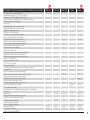
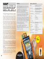
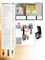
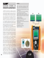
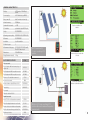
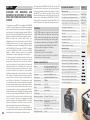
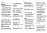
INSTRUMENTS FOR VERIFICATION ANALYSIS AND TESTING OF PHOTOVOLTAIC SYSTEMS
SOLAR 200 • SOLAR 300N • I-V 400 • SOLAR I-V • MPP 300 • THT41
®
®
Multi-string with MPP 300
see pag. 10
INSTRUMENTS FOR TESTING AND VERIFYING PHOTOVOLTAIC INSTALLATIONS
Continuity of protective conductors with 200mA
Insulation with test voltages of 50, 100, 250, 500, 1000V DC
Tripping time and current of RCDs type A, AC up to 500mA
Impedance Line/Loop, also with high resolution (0.1mΩ), and Ipsc calculation
Total earth resistance with no RCD tripping
Phase sequence
DC/AC TRMS voltage/current on single-phase systems
DC/AC TRMS voltage/current on three-phase systems
DC/AC powers on single-phase systems
DC/AC powers on three-phase systems
Power factor (cos φ) on single-/three-phase systems
Energies on single-phase and three-phase systems
Recording of mains parameters with programmable IP
Maximum number of quantities contemporarily selectable
Harmonic analysis of voltages/currents up to the 49th order
Detection of voltage anomalies (dips, peaks) in 10ms
Complete analysis according to EN50160
Inrush current of electric motors
Voltage fast transients (spikes) with a resolution of 5µs (200kHz)
Voltage unbalance (NEG%, ZERO%) and Flicker (Pst, Plt)
Display of vector diagrams and waveforms of voltages/currents
Indication of recording autonomy
Default and customizable recordings
TFT touch-screen colour display
LCD custom backlit display
Power supply by rechargeable battery and by means of external power supplier
Use of remote unit
Efficiency measurement/recording of single-string system
Efficiency measurement/recording of multi-string system up to 3 MPPTs
Efficiency measurement/recording of single-phase system
Efficiency measurement/recording of three-phase system
Irradiation measurement with reference solar cell
Temperature measurement of modules and environment
Detection of I-V curve of modules and strings
Internal database of PV modules
Measurement of modules and strings data (Voc, Vmpp, Impp, Isc, Pmax, FF, Dpmax)
Auto power off
Memory capacity
Extension of internal memory with external Compact Flash
USB port for connection of external memory sticks
PC interface with software for Windows
Context-sensitive help on the display
Saving of recordings and instant values
Dimensions (LxWxH) (mm)
Weight (batteries included) (Kg)
Safety in compliance with IEC/EN61010-1
MPP 300
SOLAR 200
SOLAR 300N
I-V 400
SOLAR I-V
•
•
•
•
•
•
•
•
•
•
•
•
•
•
•
•
•
•
•
• (1s-60m)
• (5s-60m)
251
9
•
•
•
•
•
•
•
•
•
•
•
•
•
•
•
•
•
•
•
•
•
•
•
• (with MPP 300)
•( (with MPP 300)
•
•
•
•
•
•( (with MPPT 300)
•
•
•
•
•
•
• (1000V, 10A)
• (1000V, 10A)
•
•
•
•
•
•
•
•
•
2 Mbyte
500 locations
1 month @ PI=15min, 251 par
> 200 curves
> 200 curves 8 days @ PI=10min
•
•
• (optical/USB)
• (USB)
• (ottica/USB)
• (ottica/USB)
•
•
•
•
•
•
•
300x265x140
235x165x75
235x165x75
235x165x75
235x165x75
2,3 Kg
1,2 Kg
1 Kg
1,2 Kg
1,3 Kg
•
•
•
•
•
3
SOLAR 300N
MULTIFUNCTION INSTRUMENT FOR
TESTING SINGLE-PHASE AND THREEPHASE PHOTOVOLTAIC SYSTEMS AND
ANALYZING
MAINS
QUALITY
IN
COMPLIANCE WITH STANDARD EN50160
SOLAR 300N allows carrying out all tests required for the verification
of the efficiency of single-phase and three-phase photovoltaic
systems. Testing photovoltaic systems requires contemporarily
measuring environmental parameters (incident irradiation of modules,
temperature of environment and modules) and electric parameters
(continuous power, alternating power, etc.). Typically, modules and
inverter can be positioned even at several tens of meters of distance,
thus forcing the operator to carry out measurements in different places
far from each other at the same time. To carry out these operations,
connections by means of long cables or (wireless) radio connections
could be necessary, but both these solutions are not acceptable.
Cables could hamper the operator’s movements or be a hindrance,
while radio waves would be attenuated by floors, reinforced concrete or
metal structures, thus making communication impossible.In order to
avoid the above-mentioned problems and to carry out measurements
with the necessary contemporaneity, SOLAR 300N is provided with
a remote unit, synchronized with the main unit. The remote unit is
positioned next to the photovoltaic modules and it is connected to
the probes for measuring environmental parameters (irradiation and
temperature). SOLAR 300N is connected upstream and downstream
of the inverter in order to acquire the electric parameters (continuous
power and alternating power). The synchronization between the two
units guarantees the necessary contemporaneity of measurements, the
two separate and independent units make measurements comfortable
and safe.
The instrument can be interfaced with accessory MPP300, which
extends the characteristics of SOLAR 300N by enabling recordings
on single-phase and three-phase, single-string and multi-string (up to
three strings), single-inverter and multi-inverter photovoltaic systems
(therefore also in three-phase systems provided with three single-phase
inverters).
SOLAR 300N is also a powerful instrument for the complete analysis
of mains quality in compliance with standard EN50160 (harmonic
analysis, analysis of voltage anomalies, Flicker, unbalance, etc.).
The management software TopView also provides the possibility of
creating professional reports, which can be customized by adding the
company’s logo, the customer’s data, comments, etc.
(multi-string with MPP 300 - see pag. 10)
4
FUNCTIONS
GENERAL CHARACTERISTICS
•
•
•
•
•
•
•
•
•
•
•
•
•
•
•
•
•
•
•
•
•
•
Display:
TFT, 65536 colours, (320x240pxl),
high contrast, touch screen
Power supply:
1x3.7V rechargeable Li-ION battery with
external power supply, duration > 6h, auto
power off after 5 min in stand-by
Internal memory:
15Mbyte (duration approximately 3 months @
IP = 15min and 251 parameters selected)
Memory extension:
compact flash (CF card)
PC interface:
USB 2.0
Safety:
IEC/EN61010-1
DC/AC TRMS (single/three-phase) voltage measurement
DC/AC TRMS (single/three-phase) current measurement
DC/AC (single/three-phase) power measurement
AC (single/three-phase) energy measurement
Measurement of power factor (single/three-phase)
Measurement of solar irradiation [W/m2]
Measurement of environmental and module temperature
Three-phase up to three strings PV systems (with MPP300)
Recording of voltage and current harmonics up to the 49th
Recording of voltage anomalies (dips, peaks)
Flicker analysis in compliance with standard EN50160
Recording of starting currents with a resolution of 10ms
Recording of fast voltage (spikes) with a resolution of 5µs
Analysis of mains quality in compliance with EN50160
Numerical and graphical display of each quantity
Recalling results on the display
TFT colour display with touch screen
Power supply with rechargeable Li-ION battery
Memory extension by means of CF card
Data transfer to external USB memory (memory stick)
USB port for PC connection
Help on line on the display
Insulation:
double insulation
Pollution degree:
2
Measurement category: CAT IV 600V (to earth) CAT III 1000V
(between inputs)
Unbalance:
IEC/EN61000-4-7
Power quality:
IEC/EN50160
Flicker:
IEC/EN61000-4-15
Electric power quality:
IEC/EN61000-4-30 Classe B
Dimensions:
235x165x75mm
Weight (with battery):
approx. 1kg
WITH
TOUCH
SCREEN
Some standard
accessories
SOLAR 300N
HV00300N
HT4004N
ACCESSORIES SUPPLIED
Code
Series accessories
Remote unit to record irradiation and temperature
SOLAR-02
Kit of 5 cables + alligator clips for voltage measurement
KIT800
Transducer for AC 0÷200A, diameter 40mm, 3 pcs
HT4005K
Transducer for AC/DC currents 0÷10 - 0÷100A, diameter 32mm
HT4004N
Sensor for irradiation measurement
HT304
Probe PT1000 for panel temperature
PT300N
AC/DC power supply
A0055
Rechargeable 3.7V Li-ION battery
Touch-screen pen
Graphical touch-screen display
PT400
Widows software + USB cable
Testing result on the display of SOLAR 300N
Testing result on
TopView software
TOPVIEW2007
Rigid transport suitcase
VA400
User manual on CD-ROM
LOADS
Rapid user guide
Calibration certificate ISO9000
Opzional accessories
Multi-string three-phase adaptor
MPP300
Unbatteried transducer for AC/DC currents 0÷10A,
0÷100A, max. diameter 32mm*
HT4004P
Transducer for AC currents 0÷5 - 0÷100 A, diameter 20mm
HT4005N
Rigid clamp AC 1-100-1000A/1V, diameter 54mm
HT96U
Rigid clamp AC 10-100-1000A/1V, diameter 54mm
HT97U
Rigid clamp DC 1000A/1V, diameter 50mm
HT98U
Rigid clamp AC 200-2000A/1V, diameter 70mm
HP30C2
Rigid clamp AC3000A/1V, diameter 70mm
HP30C3
Flexible clamp AC 3000A, diameter 174mm (**)
HTFLEX33D
Flexible clamp AC 3000A, diameter 274mm (**)
HTFLEX35
Interface 3x1-5A/1V for connection of external CTs
AC
INVERTER
M
A
I
N
S
kWh
DC
kWh
W/m2
°C
1
Acquiring
2
Receiving
SOLAR-02
USB
SOLAR 300N
Connection scheme
(three-phase)
SOLAR-02
SOLAR 300N
Professional transport
suitcase
HT903
Kit of belts for slinging the instrument over one’s shoulder
SP-0400
Connector with magnetic tip
606-IECN
(*) to be used with MPP300 only (**) only for using the instrument as mains analyzer
HT4005K (3 pcs)
SOLAR-02
HT304
5
I-V 400
MULTIFUNCTION INSTRUMENT FOR
VERIFICATION OF I-V CHARACTERISTIC OF
PHOTOVOLTAIC STRINGS AND MODULES
6
I-V 400 is the ideal solution for the ordinary and scheduled
maintenance of photovoltaic systems. With I-V 400, searching
for possible failures and problems in systems is extremely rapid,
efficient and intuitive. I-V 400 carries out the field measurement
of the I-V characteristic and of the main characteristic parameters
both of a single module and of module strings. The instrument
measures, together with the I-V characteristic of the device
being tested, also the values of its temperature and incident
irradiation. The acquired data are then processed to extrapolate
the I-V characteristic at standard test conditions (STC) in order
to proceed with the comparison with the nominal data declared
by the modules’ manufacturer, thus immediately determining
whether or not the string or the module being tested respects
the characteristics declared by the manufacturer.
In some PV installations, such as roof-top installations, it may be
difficult to access the module output cables. An access to the
cables at the combiner box or at the inverter’s inputs may be the
only chance. In this case the measurement of I-V characteristics
can be achieved by measuring the environmental parameters
(irradiation and temperature) through the remote optional unit
SOLAR-02. The remote unit is positioned next to the photovoltaic
modules and it is connected to the probes for measuring
environmental parameters. The synchronization between
the two units guarantees the necessary contemporaneity of
measurements making possible the extrapolation of the I-V
curve at STC without using long extension cords cable.
Output current or voltage from the module or string is measured
with the 4-terminal method, which allows extending the
measurement cables without requiring any compensation for
their resistance, thus always providing accurate and precise
measurements. In its internal memory, I-V 400 manages a
database of photovoltaic modules, which can be updated
at any time both via the management software and directly
on the instrument. Together with the measurement of the I-V
characteristic and the extrapolation of the characteristic at
standard test conditions, I-V 400 compares the obtained values
with the values declared by the manufacturer, immediately
providing the OK / NO result of the test. The operator must not
do any calculation, nor any difficult operation. The instrument
carries out the comparison rapidly and automatically.
FUNCTIONS
•
•
•
•
•
•
•
•
•
•
•
•
•
•
•
•
•
Meas. of output voltage from module/string up to 1000V DC
Meas. of output current from module/string up to 10A DC
Measurement of solar irradiation [W/m2] with reference cell
Measurement of module temperature, automatic or by means
of external probe
Meas. of output DC and nominal power of module/string
Synchronization with remote unit SOLAR-02
Numerical and graphical display of I-V characteristic
Measurement of the resistance of photovoltaic module series
Mechanical inclinometer for the detection of the incidence
angle of solar irradiation
4-terminal measuring method
Extrapolation to standard test conditions (STC)
Evaluation of testing result: OK / NO
Management of up to 30 types of photovoltaic modules in the
internal database
Internal memory for data saving
Recalling results on the display
Optical/USB port for PC connection
Help on line on the display
Some standard accessories
HT304
M304
I-V 400
HV00400V
GENERAL CHARACTERISTICS
Display:
LCD Custom, 128x128pxl,
backlit
Power supply:
6x1.5V alkaline bat. type AA LR06
Auto power off:
after 5 minutes in stand-by
Internal memory:
256kBytes
Curves which can saved:
> 200
PC interface:
optoisolated optical/USB port
Safety:
IEC/EN61010-1
Measuring accessory safety:
IEC/EN61010-031, IEC/EN10-032
Measures:
IEC/EN 60891
Insulation:
double insulation
Pollution degree:
2
Measurement category:
CAT II 1000V, CAT III 300V (to earth)
Max 1000V between inputs
Dimensions:
235x165x75mm
Weight (batteries included):
1.2kg
ACCESSORIES SUPPLIED
°C
W/m2
Simple and intuitive user
interface
Direct measurement of
I-V curve on a string of PV
modules
I-V 400
Numerical display of results with
OK result
Code
Series accessories
Kit of 4 cables with 4mm banana plugs + 4
alligator clips
KITGSC4
Kit of 2 adapters with MC3 compatible connectors
KITPVMC3
Kit of 2 adapters with MC4 compatible connectors
KITPVMC4
Reference cell for irradiation measurement
HT304
Mechanical inclinometer
M304
Windows software + optical/USB cable C2006
Transport bag
°C
W/m2
SOLAR-02
INVERTER
TOPVIEW2006
Creation of a cutomizable
database of photovoltaic modules
BORSA2051
User manual
Calibration certificate ISO9000
Opzional accessories
Probe PT1000 for cell temperature measurement
PT300N
Kit of belts for slinging the instrument over one’s shoulder
SP-0400
Remote unit to record irradiation and temperature
SOLAR-02
KIt of 2 cables banana 4mm, green/black, 25m
Rigid transport suitcase
KITPVEXT25M
VA400
I-V 400
Detection of I-V curve on a string of PV
modules with remote irradiance/temperature
measurements
7
SOLAR I-V
MULTIFUNCTION INSTRUMENT FOR
TESTING AND VERYFYING SINGLE-PHASE
PHOTOVOLTAIC INSTALLATIONS
SOLAR I-V has been designed to meet any requirement of
photovoltaic installation specialists. Further to providing the
possibility of measuring and recording the efficiency of singlestring and single-phase photovoltaic systems, SOLAR I-V also
measures the I-V characteristic both of a single module and
of module strings.Thanks to SOLAR I-V, the operator can test
the photovoltaic system and, should it give a negative result,
immediately identify the problems of the system in order to
promptly solve them. SOLAR I-V is provided with the remote unit
SOLAR-02 which permits the remote measuring of irradiation
and temperature with preliminary automatic synchronization
between main unit and remote unit. SOLAR-02 is positioned
next to the photovoltaic modules and it is connected to
the probes for measuring environmental parameters. The
synchronization between the two units guarantees the necessary
contemporaneity of measurements. In the case of PV efficiency
recordings, this grants the right efficiency calculation. For I-V
curve measurements, the synchronization permits to extrapolate
the I-V curve at STC without using long extension cords cable.
SOLAR I-V allows carrying out efficiency recordings over time with
programmable integration period from 5 seconds to 60 minutes.
Each value is automatically saved in the internal memory and
can be downloaded onto the PC for subsequent analyses. The
measured I-V characteristic is not affected by the resistance of
the measurement cables, as the measurement is carried out with
the 4-terminal measuring method. SOLAR I-V also manages a
database of photovoltaic modules, which can be updated at any
time. The measured values, correctly reported at standard test
conditions, are immediately compared with the values declared
by the manufacturer to give the OK / NO result of the test. The
operator must not do any calculation, the instrument carries out
the comparison rapidly and automatically.
The instrument can be interfaced with accessory MPP300, which
extends the characteristics of SOLAR I-V by enabling recordings
on single-phase and three-phase, single-string and multi-string
(up to three strings), single-inverter and multi-inverter photovoltaic
systems (therefore also in three-phase systems provided with three
single-phase inverters).
(multi-string with MPP 300 - see pag. 10)
8
FUNCTIONS
•
•
•
•
•
•
•
•
•
•
•
•
•
•
•
•
•
•
•
•
•
•
•
•
•
•
GENERAL CHARACTERISTICS
Photovoltaic installation testing
Measurement of DC/AC TRMS voltage and current
Measurement of DC/AC powers on single-phase systems
Measurement of solar irradiation [W/m2] with reference cell
Measurement of environmental and module temperature by
means of external probe
Synchronization with remote unit SOLAR-02
Display of real-time irradiation and temperature
Use of PDC compensation ratios according to environmental
and module temperature
Three-phase up to three strings PV systems (with MPP300)
Recording of parameters with programmable IP (5s – 60min)
I-V characteristic measurement
Meas. of output voltage from module/string up to 1000V DC
Meas. of output current from module/string up to 10A DC
Measurement of solar irradiation [W/m2] with reference cell
Measurement of module temperature, automatic or by means
of external probe
Meas. of output DC and nominal power from module/string
Synchronization with remote unit SOLAR-02
Numerical and graphical display of I-V characteristic
Measurement of the resistance of photovoltaic module series
Mechanical inclinometer for the detection of the incidence
angle of solar irradiation
4-terminal measuring method
Extrapolation to standard test conditions (STC)
Evaluation of testing result: OK / NO
Management of up to 30 types of photovoltaic modules in the
internal database
Common characteristics
Internal memory for data saving
Recalling results on the display
Optical/USB port for PC connection
Help on line on the display
Display:
LCD custom, 128x128pxl, backlit
Power supply:
6x1.5V alkaline bat. type AA LR06
Auto power off:
after 5 minutes in stand-by
PV testing duration:
1.5 hours (@IP=5s); 8 days (@IP=10min)
Curves which can be saved: > 200 curves
PC interface:
optoisolated optical/USB port
Safety:
IEC/EN61010-1
Measuring accessory safety:
IEC/EN61010-031, IEC/EN61010-032
Measures on PV modules:
IEC/EN60891
Insulation
double insulation
Pollution degree:
2
Measurement category:
CAT II 1000V DC, CAT III 300V (to
earth) Max 1000V between inputs
Dimensions:
235x165x75mm
Weight (batteries included): 1.3kg
Some standard accessories
HT4004N HT4005K SOLAR-02
HT304
M304
SOLAR I-V
HV0000IV
ACCESSORIES SUPPLIED
Code
Series accessories
Remote unit to record irradiation and temperature
SOLAR-02
Kit of 4 cables with 4mm banana plugs + 4 alligator clips
KITGSC4
Kit of 2 adapters with MC3 compatible connectors
KITPVMC3
Kit of 2 adapters with MC4 compatible connectors
KITPVMC4
Transducer for AC 0÷200A, diameter 40mm
HT4005K
Transducer for AC/DC currents 0÷10 - 0÷100A,
diameter 32mm
HT4004N
Reference cell for irradiation measurement
HT304
Probe PT1000 for environmental and module temperature
PT300N
Mechanical inclinometer
Windows software + optical/USB cable C2006
Transport bag
Testing / Recording in progress
Testing result of photovoltaic
system
Numerical display of results with
OK result
Graphical display of an I-V curve
with OK result
M304
TOPVIEW2006
°C
W/m2
°C
BORSA2051
W/m2
User manual on CD-ROM
Calibration certificate ISO9000
INVERTER
SOLAR-02
Rapid user guide
Opzional accessories
Multi-string three-phase adaptor
MPP300
Unbatteried transducer for AC/DC currents 0÷10A,
0÷100A, max. diameter 32mm*
HT4004P
Transducer for AC currents 0÷5 - 0÷100 A, diameter 20mm
HT4005N
Rigid clamp AC 1-100-1000A/1V, diameter 54mm
HT96U
Rigid clamp AC 10-100-1000A/1V, diameter 54mm
HT97U
Rigid clamp DC 1000A/1V, diameter 50mm
HT98U
Kit of belts for slinging the instrument over one’s shoulder
SP-0400
KIt of 2 cables banana 4mm, green/black, 25m
KITPVEXT25M
Rigid transport suitcase
Connector with magnetic tip
Direct measurement of
I-V curve on a string of PV
modules
SOLAR I-V
Detection of I-V curve on a string of PV
modules with remote irradiance/temperature
measurements
SOLAR I-V
VA400
606-IECN
(*) to be used with MPP 300 only
Connection scheme
(single-phase plant)
9
MPP 300
ACCESSORY FOR MEASURING AND
RECORDING THE EFFICIENCY OF SINGLEPHASE AND THREE-PHASE MULTI-STRING
SYSTEMS
10
The innovative accessory MPP300, used together with SOLAR300N
or SOLAR I-V, allows measuring and recording the main parameters
which characterize single-phase and three-phase, single-string and
multi-string (up to three strings) photovoltaic systems. MPP300 is
perfect for use in systems with three-MPPT three-phase inverter and
in three-phase systems provided with three single-phase inverters.
MPP300 is provided with a practical anti-shock “field” case,
lightweight and small in size. The front panel carries the LEDs for
operating information and the DC and AC inputs for upstream
and downstream connection of the inverter(s). MPP300 interfaces
with SOLAR300N via USB connection and SOLAR I-V via wireless
connection. SOLAR300N and SOLAR I-V are used for MPP300
settings, to start/stop recording electrical and environmental
parameters and to enable the download of the recorded values.
The distance between the photovoltaic modules and the inverter
is often considerable, and this forces the operator to carry out
measurements in different places at the same time. Therefore,
it would be necessary to lay long connection cables between the
environmental probes and the instrument. These cables could
hamper the operator’s movements, be a hindrance, etc. This kind
of connection is therefore not acceptable. In case of photovoltaic
installations on buildings, the so-called photovoltaic roofs, in addition
to the problem of the distance between modules and inverter, the
presence of floors, of reinforced concrete or metal structures, etc.
must be taken into consideration. These structures would make
a possible (wireless) radio connection between the environmental
probes and the instrument impossible, because of signal attenuation.
In order to avoid the above-mentioned problems and to carry out
measurements with the necessary contemporaneity, MPP300 is
synchronized with the remote unit SOLAR-02 (provided as standard
accessory of master instrument SOLAR300N or SOLAR I-V). The
remote unit SOLAR-02 is positioned next to the photovoltaic modules
and it is connected to the probes for measuring environmental
parameters (irradiation and temperature). MPP300 is connected
upstream and downstream of the inverter in order to acquire the
electric parameters (continuous power and alternating power).
The synchronization between the two units guarantees the
necessary contemporaneity of measurements, the two separate and
independent units make measurements comfortable and safe.
The master instrument SOLAR300N or SOLAR I-V is only used in the
initial and final phase of recording, and it does not play any active role
while recording electrical and environmental parameters. Therefore,
while MPP300 and SOLAR-02 respectively record the electrical
and environmental parameters of the system being measured, it is
possible to use the master instrument SOLAR300N or SOLAR I-V for
carrying out other measurements. For example, with SOLAR I-V it is
possible to measure the I-V characteristics of strings and modules.
Code
Series accessories
Set of 2 cables, 2m, for DC voltage measurement, 3pcs
KITMPPDCW
Set of 2 alligator clips for DC voltage measurement, 3pcs
KITMPPDCC
Set of 4 cables, 2m, for AC voltage measurement
KITMPPACW
Set of 4 alligator clips for AC voltage measurement
KITMPPACC
Rechargeable Li-ION battery
FUNCTIONS
•
•
•
•
•
•
•
•
•
•
•
ACCESSORIES PROVIDED
AC/DC battery charger power supply
DC/AC TRMS voltage meas. (single-phase and three-phase)
DC/AC TRMS current meas. (single-phase and three-phase)
DC/AC power measurement (single-phase and three-phase)
Power factor measurement (single-phase and three-phase)
Simultaneous measurements up to 3 strings (max 3 MPPT)
Connection with master unit SOLAR300N and SOLAR I-V
Power supply with rechargeable Li-ION battery
LED operating indications
USB port for connection to unit SOLAR300N
RF connection for connection to SOLAR-02 and SOLAR I-V
Internal memory for saving recordings
USB cable
Carrying bag for accessories
A0055
C2007
BORSA2051
User manual on CD-ROM
Quick guide for use
ISO9000 calibration certificate
Opzional accessories
Transducer for AC 0÷200A, diameter 40mm
HT4005K
Unbatteried transducer for AC/DC currents 0÷10A,
0÷100A, max. diameter 32mm
HT4004P
Rigid clamp AC 1-100-1000A/1V, diameter 54mm
HT96U
GENERAL CHARACTERISTICS
Rigid clamp AC 10-100-1000A/1V, diameter 54mm
HT97U
Inputs:
Rigid clamp DC 1000A/1V, diameter 50mm
HT98U
Rigid clamp AC 200-2000A/1V, diameter 70mm
HP30C2
Rigid clamp AC3000A/1V, diameter 70mm
HP30C3
Flexible clamp AC 3000A, diameter 174mm
HTFLEX33D
Flexible clamp AC 3000A, diameter 274mm
HTFLEX35
Connector with magnetic tip
606-IECN
3 DC voltage channels (CH1, CH2, CH3), 3
DC current inputs (CH1, CH2, CH3),
4 AC voltage inputs (L1, L2, L3, N), 3 AC
current inputs (L1, L2, L3)
Front panel:
4 two-colour LEDs (green, red)
Power supply:
Rechargeable Li-ION battery. Duration > 3 hours
Internal memory:
2 MBytes
External interface:
USB + RF
Safety:
IEC/EN61010-1
Insulation:
double insulation
Pollution level:
2
Mechanical protection:
IP40 (open), IP65 (closed)
Measurement category:
CAT IV 300 V AC (to earth), 600 V AC
(between inputs)
CAT III 1000 V DC (to earth), 1000 V DC
(between inputs)
Size:
300 x 265 x 140 mm
Weight (battery included):
2.3 kg
Useful carrying case for transport
Multi-string PV plant tested by means of MPP 300
Inverter
STRING 1
(MPPT1)
M
A
I
N
S
STRING 2
(MPPT2)
STRING 3
(MPPT3)
°C
W/m2
DC Side
AC Side
SOLAR-02
Acquiring
IRR + TEMP
RF
Connection
SOLAR-02
Connection diagram
MPP 300 - SOLAR 300N
via USB connection
MPP300 - SOLAR I-V
via RF connection
MPP 300
HVMPP300
Start
Stop
Settings
RF
Start
Stop
Settings
Connection
USB
Download
Connection
Download
SOLAR I-V
SOLAR 300N
11
SOLAR 200
MULTIFUNCTION INSTRUMENT FOR SAFETY
VERIFICATION OF SINGLE-PHASE AND
THREE-PHASE PHOTOVOLTAIC SYSTEMS
SOLAR200 is an innovative instrument designed for carrying
out electrical safety verifications on photovoltaic systems
in compliance with the relevant safety requirements. The
instrument is very easy to use and has a wide range of
functions which can be selected by means of the simple
multi-language menu. Measurements can be started both
by pressing the button located on the instrument body
and by pressing the button located on the remote probe
(optional accessory PR400) which makes carrying out
more measurements in sequence very simple. The help on
line, which can be selected by the user and is active for
any function, is a valid support for the connection of the
instrument to the system to be tested. SOLAR200 is provided
with an internal memory and an optical/USB interface for PC
connection and for transferring measured data, which can
be analyzed with the dedicated software.
FUNCTIONS
GENERAL CHARACTERISTICS
• Continuity of protective conductors with 200mA
• Insulation with test voltages of 50, 100, 250, 500,
1000VDC
• Tripping time of RCDs type A, AC, general and selective,
with nominal current up to 500mA
• Tripping current of RCDs type A, AC, general and
selective, with nominal current up to 500mA
• Impedance of Loop/Line P-N, P-P, P-PE, also with high
resolution (0,1mΩ with optional accessory IMP57),
and Ipsc calculation.
• Total earth resistance with no RCD tripping
• Contact voltage
• Phase sequence
• Activation of measurements with optional remote probe
PR400
• Help on line on the display
• Saving of results
• Optical/USB interface for PC connection
Display:
LCD custom, backlit
Power supply:
6x1.5V alkaline bat. type AA IEC LR06
Internal memory:
500 locations
PC interface:
optoisolated optical connector
Safety:
IEC/EN61010-1
Insulation:
double insulation
Pollution degree:
2
Measurement category:
CAT III 240V (to earth), CAT III
415V (between inputs)
Reference standards:
IEC/EN61557-1
Dimensions:
235x165x75mm
Weight (bat. included):
approx. 1.25kg
ACCESSORIES SUPPLIED
Code
Series accessories
Cable with three-pin shuko plug
C2033X
Kit of 3 cables + 3 alligator clips + 1 probe
Transport bag
UNIVERSALKIT
BORSA75
User manual
Calibration certificate ISO9000
Optional accessories
Windows software for PC + optical/USB cable
12
SOLAR200
HV000200
TOPVIEW2006
Remote probe for test activation
PR400
Accessory for measuring loop impedance with high resolution
IMP57
Kit of belts for slinging the instrument over one’s shoulder
SP-0400
IMP57
Accessory for measuring
loop impedance with high
resolution
PR400
Remote probe
THT41
GENERAL CHARACTERISTICS
INFRARED THERMAL CAMERA FOR
PROFESSIONAL USE
Measuring range:
-20°C ÷ 250°C
Thermal sensitivity:
0.1°C @ 30°C
Field of view (FOV):
21°x16° (11mm lens)
THT41 is a hand-held infrared camera developed to quickly
become the technician’s best friend. In a rugged and ergonomic
design, THT41 is robust and shock-resistant for any working
environment. The instrument has a colour LCD display, saves
the images on SD-card in standard JPG format. It also allows
transferring the data onto the PC via USB interface. THT41
is specifically designed for products predictive maintenance,
electrical inspections, non-destructive testing, process control
applications, quarantine inspection. security monitoring
solutions, firefighting finding and rescue, building energy
testing and diagnostics, veterinarian helper, etc.
Precision:
±2%reading or ±2°C
IR sensor resolution:
160x120pxl
TFT colour display:
LCD, 3.6”
Focusing:
manual
Image frequency:
50Hz
Emissivity correction:
0.01 1.00
Measuring cursors:
hot / cold point
Measuring functions:
correction according to distance, reflected
temperature, relative humidity
Storage of images:
SD Card 2GBytes
Image format:
standard JPG
Saved images:
> 1000
Power supply:
6x1.2V NiMH batteries type AA
Duration:
> 2 hours
Mechanical protection:
IP54
Size (LxWxH):
240 x 111 x 124mm
ACCESSORIES
Code
Standard accessories
11mm lens and protection cover
2GB SD card and card reader
12 AA rechargeable batteries
AC adapter
USB extension cable
USB driver
Wirst strap
Windows ThermoVIewPRO software
User manual
ISO9000 calibration certificate
Safety case
Optional accessories
Sun shield
Universal tripod adapter
Thermal image of
defective PV modules
Weight (batteries included): 0.73kg
SSHIELD49
TRIPO49
Complete set for transport of accessories
THT41
HN000041
13
Q1
UNIVERSAL CRIMP TOOL
Special tool for cabling photovoltaic systems. It has the
following characteristics:
- in hardened and tempered chrome-vanadium steel
- handles in non-slip material, two components
- interchangeable dies and locators allow working with
different types of connectors with a single tool
The high-precision crimp tool Q1 has been designed to
guarantee professional connections with a single manual tool.
The tightening force is multiplied thanks to an internal system
of levers which allows a 30% reduction of the force normally
necessary. Q1 is provided with a practical case in anti-shock
resin without dies and without locators, with:
- crimp tool Q1
- L wrench for die assembly
- adjustable wrench
Customization according to requirements with the available
dies and locators (special dies available on demand)
DIES
Type of connector
Metel code
Diameter (mm2)
MC4
HU000662
2,5/4,0/6,0
Tyco
HU000660
1,5/2,5/4,0/6,0
MC3
HU000663
MC4
HU000661
Tyco
HU000559
LOCATORS
Type
Metel code
Interchangeable dies and locators
Thanks to the locator, the terminal is always crimped in the
correct position, thus simplifying the operation, without the
need to use “three hands” for crimping. A wide range of
dies is available, in order to satisfy the requirements of most
modern connectors.
14
MC3
HU000664
2,5/4,0/6,0
TOP QUALITY
MADE IN
GERMANY
Q1
HU000676
Q1:
NEW,
VERSATILE,
THE ONE
Huber & Shuner
HU000692
2,5/4,0
Huber & Shuner
HU000671
4,0/6,0
Mounting examples of MC3 with Q2
Q2
SPECIAL TOOL FOR MC3 ASSEMBLY
(inserting the rubber connector onto the
crimped cable)
Q2 is a practical clamp for mounting connector MC3 once
the terminal has been crimped to the cable. The 3 thimbles
provided allow assembly on cables with different diameters
(from 2.5 to 10 mm2). Thanks to its small size (325 mm)
and its weight (460 g), this tool can be used directly on site
and even on a roof. Lightweight and portable, it is made of
anti-shock plastic.
Prepare crimped connector MC3
and the insulating connector
(male or female)
Choose the thimble according to
cable diameter
Insert the thimble with the connector into the
appropriate housing for the cable
TOP QUALITY
MOUNTING OF MC3
INNOVATIVE
Built-in thimbles
MADE IN
GERMANY
With the right hand, completely insert the MC3 connector
into the thimble
Press the clamp until the thimble is completely inserted in the
connector and insert the crimped cable, and fasten it with the
relevant cable holder.
Continue pressing the tool
until no resistance is felt. Then
remove the cable by extracting
the relevant cable holder. By
using this innovative tool, it
is possible to cable systems
directly on site, thus saving
installation times and costs.
AND SIMPLY
Inspection window
Cable housing and holder
Safety closure
Q2
HU000675
While the costs of
components are decreasing
and their performance is
significantly booming up, the
photovoltaic installations
are very common either on
buildings’ roofs or installed
on the ground.
SAFETY
The problems involved in the
installation of photovoltaic
systems, however, are to
be solved in terms of safety,
testing and maintenance
requiring specific solutions.
In a typical building installation modules
are usually placed on the roof and the inAll this makes safety testing even more ne- verter is often in the basement.
cessary.
Such a condition is critical because, to test
Safety is not to be neglected in the assembly the equipment both electrical and environand maintenance of a photovoltaic installa- mental parameters are to be measured
tion.
simultaneously even though very far from
The regulations in force state that quality each other. Only the use of suitable equimarks and certification on components are pment can grant correct measurements
not enough and that an instrumental measu- carried out in a suitable, fast and conve- In this case you can pinpoint the damaged
modules and promptly replace them.
rement is required.
nient way.
of the photovoltaic modules under test, it is necessary
to measure the solar radiation which they are subject
to by means of a transducer with features similar to
the modules’ ones. Using a sensor with a different
manufacturing technology could lead to inconsistent
measurements of solar radiation, and consequently to
incorrect measurements of the modules under test. For
this reason HT photovoltaic testers are provided with the
reference cell HT304 as standard accessory.
HT304 is featured as follows:
- it is provided with a built-in temperature sensor allowing
compensation of the measured values;
- it is provided with two sensors made of monocrystalline
and polycrystalline silicon respectively to better suit the
manufacturing technology of the modules to be tested;
- it better reflects the close correlation of the modules
under test with the solar radiation incidence angle as well
as with its spectrum composition;
- it grants a quick response the same as the photovoltaic
modules.
This last feature is crucial in case of measurements taken
under conditions of variable cloudiness.
WITH
SOLAR 200
TESTING
WITH SOLAR 300N
AND SOLAR I-V
MAINTENANCE
The photovoltaic installation is an electrical
system under all respects and its safety must
be certified in compliance with the regulations in force.
As the photovoltaic modules are installed outdoors and directly irradiated by the sun, they
are subject to extreme environmental conditions such as hot weather in summer, frost in
winter, rain and hail etc.
To apply for special tariffs the electricity user
needs to provide a test certificate along with
sundry documents. This document certifies
that the installation ensures a minimum efficiency level. It is therefore necessary to employ measuring instruments bringing about
significant practical problems.
The outdoor installation, with consequent exposure to extreme environmental conditions,
can lead to a rapid deterioration of the modules as well as a sharp decrease in the performance of the whole photovoltaic installation.
Photovoltaic modules partially convert solar radiation into
electric power. The efficiency of photovoltaic modules is
strongly affected by several factors such as:
- operating temperature of modules;
- manufacturing technology of modules;
- angles at which solar radiation hits the modules’ surface;
- spectral composition of solar radiation; etc.
It is obvious that, to properly evaluate the performance
HT ITALIA SRL Via della Boaria 40 48018 Faenza (Ra) Italy - Phone: +39.0546.621002 Fax: +39.0546.621144 E-mail: [email protected]
I-V400
AND SOLAR I-V
The energy produced and the consequent economic benefit can be reduced considerably.
It should be advisable therefore to periodically check the installation comparing the performance of the modules as specified by their
manufacturer. By measuring the module I-V
feature and comparing it with the rating you
can assess whether they are granting adequate performances, whether any decrease
falls within the natural performance decay, or
whether one or more modules are faulty.
www.ht-instruments.com
®
STAMPA: “LABANTI & NANNI BO 03-2011
Why to use a reference cell
CONCEPT: “CAMPOVISIVO” - FAENZA ITALY
Photovoltaic
installations are
becoming
more and more
popular