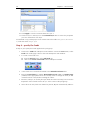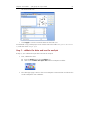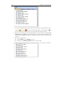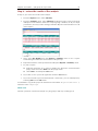
1
Repute Version 1.5 User Manual PILE GROUP DESIGN 2 Repute 1.5 User Manual Information in this document is subject to change without notice and does not represent a commitment on the part of Geocentrix Ltd. The software described in this document is furnished under a licence agreement or non-disclosure agreement and may be used or copied only in accordance with the terms of that agreement. It is against the law to copy the software except as specifically allowed in the licence or non-disclosure agreement. No part of this manual may be reproduced or transmitted in any form or by any means, electronic or mechanical, including photocopying and recording, for any purpose, without the express written permission of Geocentrix Ltd. Chapters 1-6, ©2002-6 Geocentrix Ltd. All rights reserved. Chapter 7, ©2002 Geomarc Ltd. All rights reserved. “Geocentrix” is a registered trademark and “Repute” a trademark of Geocentrix Ltd. PGroupN is used under exclusive licence from Geomarc Ltd. PGROUP code used under licence from TRL Ltd. “Microsoft” and “Windows” are registered trademarks of Microsoft Corporation. “IBM” is a registered trademark of International Business Machines Corp. “Adobe” and “Acrobat” registered trademarks of Adobe Systems Incorporated. Other brand or product names are trademarks or registered trademarks of their respective holders Set in Optimum using Corel® WordPerfect® 12. Release Candidate 1 (07/06). Printed in the UK. Acknowledgements 3 Acknowledgments Repute 1.0 was designed and written by Dr Andrew Bond of Geocentrix, with components developed by Ian Spencer and Vassilis Poulopoulos. PGroupN was designed and written by Dr Francesco Basile of Geomarc/Halcrow. A special note of recognition goes to the late Dr Ken Fleming of Cementation Foundations Skanska for his invaluable advice and support during the development of PGroupN. The Repute User Manual was written by Andrew Bond and Francesco Basile. The following people and organizations assisted with the testing of the program: Jack Offord, Francesco Basile, Halcrow Group. 4 Repute 1.5 User Manual Table of contents 5 Table of contents Acknowledgments . . . . . . . . . . . . . . . . . . . . . . . . . . . . . . . . . . . . . . . . . . . . . . . . . . . 3 Table of contents . . . . . . . . . . . . . . . . . . . . . . . . . . . . . . . . . . . . . . . . . . . . . . . . . . . . 5 Chapter 1 Introducing Repute . . . . . . . . . . . . . . . . . . . . . . . . . . . . . . . . . . . . . . . . . . . . . . . . . . 9 About this manual 9 Other sources of information 10 Windows documentation and online help 10 Reference manual 10 Repute’s help system 10 Technical support 10 Chapter 2 Installing and running Repute . . . . . . . . . . . . . . . . . . . . . . . . . . . . . . . . . . . . . . . . . System requirements To install Repute To run Repute To uninstall Repute On Windows XP On Windows 95/98/Me/NT4/2000 13 13 13 14 14 14 15 Chapter 3 Overview . . . . . . . . . . . . . . . . . . . . . . . . . . . . . . . . . . . . . . . . . . . . . . . . . . . . . . . . . Key features New to Repute 1.5 User interface Title bar Menu bar Toolbar Tabbed notebooks Progress Bar Status Bar Sizing grip Tools Pile Group Wizard Licence Registration Wizard Online help 17 17 17 17 18 18 19 19 20 20 20 20 20 21 22 6 Repute 1.5 User Manual To open Repute’s online help To navigate Repute’s online help 23 23 Chapter 4 Tutorial 1 – pile group in clay & sand . . . . . . . . . . . . . . . . . . . . . . . . . . . . . . . . . . . Worked example Steps Step 1 - enter basic project information Step 2 - define the pile group Step 3 - enter the layers Step 4 - specify the loads Step 5 - validate the data and run the analysis Step 6 - review the results of the analysis What next? 25 25 25 26 27 28 30 31 33 33 Chapter 5 Tutorial 2 – non-linear analysis of pile group in stiff clay overlying rock . . . . . . . Worked example Steps Step 1 - enter basic project information Step 2 - change the analysis to non-linear Step 3 - enter the soil and rock layers Step 4 - define the pile group Step 5 - specify the loads Step 6 - run the analysis Step 7 - display the load-displacement curve for the pile group Step 8 - apply limiting stresses What next? 35 35 35 36 37 38 39 40 41 42 43 45 Chapter 6 Tutorial 3 – asymmetric pile group under 3D loading . . . . . . . . . . . . . . . . . . . . . . Worked example Steps Step 1 - open and modify an existing project Step 2 - specify the 3-dimensional loading Step 3 - create a new pile group Step 4 - move the piles into an asymmetric layout Step 5 - review the pile layout Step 6 - run the analysis What next? 47 47 48 48 49 50 52 52 53 54 Chapter 7 Background theory and assumptions . . . . . . . . . . . . . . . . . . . . . . . . . . . . . . . . . . . 55 The boundary element method 55 Table of contents PGroupN method of analysis Choice of soil parameters Non-linear soil model References 7 56 57 57 59 8 Repute 1.5 User Manual Chapter 1: Introducing Repute 9 Chapter 1 Introducing Repute Repute™ is a computer program for determining the response of pile groups to 3dimensional loading, using linear or non-linear soil models. Repute features: ! a notebook style user interface for easy entry of your pile, layer, and loading data ! a lightning-fast calculation engine based on the boundary-element method ! extensive reporting capabilities via its in-built web browser, rich text viewer, and graph control Repute's calculation engine is the leading-edge program PGroupN (used under exclusive licence from Geomarc), which provides a complete 3D non-linear boundary element solution of the soil continuum. This overcomes limitations of traditional interaction-factor methods and gives more realistic predictions of deformations and the load distribution between piles. Repute is the first pile-group design program to deal efficiently with soil non-linearity, avoiding exaggerated stresses and consequential high loads and bending moments at pile-group corners (a common limitation of linear-elastic models). Benefits of this include greatly improved designs and significant savings in construction costs. Repute is supplied with a detailed User Manual (this book), including three step-by-step tutorials. A separate chapter explains the background theory and assumptions behind the program. Technical support for Repute is provided free-of-charge for 30 days and thereafter via an annual support agreement. Service Packs are placed on the Geocentrix website (www.geocentrix.co.uk/support) at regular intervals. About this manual The Repute User Manual (this book) explains how to install and use Repute. It includes an overview of the program, three step-by-step tutorials, and a separate chapter giving background theory and assumptions behind the program. The latest version of this manual (including any corrections and/or additions since the program’s first release) is available in electronic (Adobe® Acrobat®) format from the Geocentrix website. Please visit www.geocentrix.co.uk/repute and follow the links to Repute’s support pages. 10 Repute 1.5 User Manual Other sources of information Windows documentation and online help This manual assumes that you are familiar with Microsoft® Windows® operating systems, Windows 95/98/Me or Windows NT4/2000/XP. If not, please refer to your Windows documentation and online help for assistance. Reference manual The Repute Reference Manual gives further information about the geotechnical theory that underpins Repute’s calculations. The manual assumes you have a working knowledge of the geotechnical design of pile groups. This manual is provided in electronic (Adobe Acrobat) format only. Repute’s help system Repute’s help system contains detailed information about the program, including all the information contained in the Repute User Manual, plus additional information regarding Repute’s user interface. Help appears in a separate window to Repute, allowing you to view the help topics while you continue to work with Repute itself. To open the help system: Press F1 Click the Help button in any dialog box Choose a command from the Help menu Technical support Technical support for Repute is available direct from Geocentrix or through your local distributor. If you require technical support, please contact Geocentrix by any of these means: Chapter 1: Introducing Repute Repute Technical Support Geocentrix Ltd Scenic House, 54 Wilmot Way Banstead, Surrey SM7 2PY, United Kingdom Please quote your licence number on all correspondence 11 Tel.: +44 (0)1737 373963 Fax: +44 (0)1737 373980 E-mail: [email protected] Web: www.geocentrix.co.uk Please be at your computer and have your licence number ready when you call 12 Repute 1.5 User Manual Chapter 2: Installing and running Repute 13 Chapter 2 Installing and running Repute Repute runs on most Microsoft Windows operating systems. Installation procedures vary slightly from one operating system to the next, as described in this chapter. Although you can install Repute on as many computers as you like, you will only be able to run the program on those computers to which you attach an authorized security key. System requirements Repute runs on Microsoft Windows 95/98/Me and Microsoft Windows NT4/2000/XP and requires these minimum resources to function properly: ! Intel® Pentium® (or higher) processor ! 32 MB RAM ! At least 30Mb free space on your hard disk for a complete installation ! CD-ROM drive ! VGA or higher resolution monitor displaying 256 or more colours ! Any printer supported by Windows ! A mouse or other pointing device supported by Windows To install Repute 1. 2. 3. 4. Remove any previous installation of Repute via Windows’ Control Panel. Insert the Geocentrix Software CD into your CD-ROM drive. The Geocentrix CD Browser should automatically appear on your screen. If not, click Run... on Windows’ Start menu, type X:\setup.exe in the Open box (where X is the letter of your CD-ROM drive), and click OK. Click on the text “Click here to install Repute” or the arrow to run the Repute installation program. When asked “Do you want to run or save this file?” click Run. If a security 14 Repute 1.5 User Manual 5. 6. 7. 8. 9. 10. 11. 12. 13. 14. warning appears, click Run. Follow the instructions on the welcome screen and then click Next. Accept the license agreement and click Next. Read the Readme Information for latebreaking news about Repute and click Next. Enter y o ur user information exactly as given on the program’s packaging and click Next. Select a destination folder and click Next. Select an installation type and click Next. Click Next to install the application. When the device driver installation (HDD_install) starts, please allow several minutes for it to complete. Then click Close. When you are told that Repute has been successfully installed, click Finish. Click Exit to close the Geocentrix CD Browser. Screenshots are shown for Windows XP and may differ on other operating systems. To run Repute To run Repute, first connect the supplied key to your computer’s USB/parallel port and then click Start > All Programs > Geocentrix > Repute 1.5. Note: in Windows XP and later, the Programs menu is called All Programs. To uninstall Repute On Windows XP 1. 2. 3. 4. 5. Exit Repute On Windows’ Start menu, click Control Panel Double-click on the Add or Remove Programs icon Select Change or Remove Programs on the left hand side of the Add or Remove Programs window Select Repute in the Currently installed programs box and click the Remove button that appears when you do so Chapter 2: Installing and running Repute 6. 7. 8. 15 Answer Yes when asked Are you sure you want to remove Repute from your computer? When Windows has finished updating your system, click Close to close the Add or Remove Programs window Close Windows’ Control Panel On Windows 95/98/Me/NT4/2000 1. 2. 3. 4. Exit Repute On Windows’ Start menu, click Settings > Control Panel Double-click on the Add or Remove Programs icon On the Install/Uninstall page, select Repute from the list of programs installed on your system 5. Click the Add/Remove button 6. Select Remove in the Application Maintenance window and click Next 7. Click Next to confirm that you want to remove Repute 8. When Windows has finished updating your system, click Finish 9. Click OK to close the Add/Remove Programs window 10. Close Windows’ Control Panel 16 Repute 1.5 User Manual Chapter 3: Overview 17 Chapter 3 Overview This chapter gives you an overview of Repute’s main features. Key features The key features of Repute are: ! a notebook style user interface for easy entry of your pile, layer, and loading data ! a lightning-fast calculation engine based on the boundary-element method ! extensive reporting facilities via its in-built web browser, rich text viewer, and graph control ! a Pile Group Wizard to facilitate the speedy creation of large pile groups ! a detailed messaging system providing an audit trail of the program’s operations ! built-in SI/Imperial unit converters ! extensive data-validation on data-entry and prior to calculation ! context-sensitive online help ! links to supporting material on the Geocentrix website New to Repute 1.5 New calculation features: ! 6000 degree-of-freedom engine for very large pile groups New user interface features: ! separate Data Input notebook, allowing easy entry of geotechnical, structural, and loading information ! new Results notebook, giving clear presentation of various formst of data outut (HTML reports, graphs, and text output) ! twin-display of input/ouput makes working with the program even easier ! re-sizable windows allows better use of available screen space Extensive new graphing capabilities, including: ! change line colours, line weight, etc ! change graph title and font ! change axis titles and fonts 18 Repute 1.5 User Manual ! show/hide selected lines ! fully cutomizable background grid ! new Graph menu provides quick access to results in visual form Improved in Repute 1.5 ! Re-designed data entry controls are now even easier to use ! Collapsable data entry controls allows information to be disclosed only when needed ! Re-designed main menu has more logical layout ! Smaller program footprint uses less of computer's hard disk ! Updated User Manual with revised Tutorials ! Simpler installation procedure ! Licence/dongle reminders made less frequent User interface Repute’s user interface comprises a title bar, menu bar, toolbar, a tabbed notebook for the input data, a tabbed notebook for the project results, a status and progress bar, and sizinggrip. Title bar The title bar displays the program’s name, version number, and edition. To view all of the program information, select About Repute... from the help menu. You may be asked to provide this information when contacting Geocentrix for technical support. Chapter 3: Overview 19 If you left-click on the Repute icon at the left-hand end of the title bar, a drop-down menu will appear with commands for sizing, moving, or closing Repute. The row of buttons at the right-hand end of the title bar provide quick ways of minimizing, maximizing, or closing Repute. Menu bar Repute’s menu bar provides groups of commands under the following headings: ! File ! Edit ! View ! Project ! Build ! Reports ! Graphs ! Tools ! Online ! Window ! Help Further information about the commands that appear on these drop-down menus can be found in Repute’s online help. Commands that appear in grey are disabled (usually because that command is inappropriate or temporarily disallowed). For example, the File > Save command is disabled until you make changes to the current project. Toolbar The toolbar provides buttons that help you perform certain tasks quickly, without using the menus. The pictures on the toolbar buttons correspond to the pictures that appear to the left of the corresponding menu command. If you move the cursor over a toolbar button, a popup window will appear giving a brief explanation of what the button does. Those toolbar buttons that have a downwards pointing arrow next to them display a drop- 20 Repute 1.5 User Manual down menu when clicked. Tabbed notebooks Most of Repute’s main window is taken up two tabbed notebooks, for Data Input and Results, which have separate pages for: ! Project, Piles, Layers, Loads, and Options under Data Input ! Messages, Reports, Graphs, and Text under Results All pages under Data Input have a Help button in their top-right hand corners. When you click the Help button, Repute’s help file opens and displays the topic which explains the items on the currently selected notebook page. The Data Input pages also have Apply and Revert buttons in their top-right hand corners. When you make changes to the data displayed on any of these pages, you need to click Apply to commit those changes to Repute’s internal memory. Alternatively, click Revert if you wish to discard the changes you have made. If you forget to click Apply or Revert when leaving a data-entry page, Repute will remind you to do so. Progress Bar The progress bar gives an indication of how long a task takes to complete. Status Bar The status bar displays the name of the project you currently have opened and the word “Modified” if the project has been changed since it was last saved, or “Unmodified” if it has not been changed. In addition, the status bar shows the full file path of the project open (once it has been saved at least once). Sizing grip The sizing grip allows you to resize Repute’s main window, which, for example, might be needed to see all the information given in one of Repute’s detailed reports. Tools Repute provides a number of tools to increase your efficiency in using the program. You can see what tools are available to you by clicking on Tools on the menu bar. Chapter 3: Overview 21 Pile Group Wizard The Pile Group Wizard is designed to speed up your use of Repute, by generating piles on a grid layout that you specify. The piles’ properties can be edited via Repute’s tabbed notebook once the Wizard has created them. The best way to learn how to use the Pile Group Wizard is to follow Tutorials 1-3, which make extensive use of the wizard. Licence Registration Wizard The Licence Registration Wizard assists you in registering your copy of Repute, allowing you to unlock the particular edition you have purchased. Until Repute has been registered, only those features included in the Trial Edition of the program are available. To register Repute: 1. 2. 3. Select the Product you have purchased from those listed. Enter your company’s name in the Licensed To (Name) box. Enter the licence number provided by Geocentrix in the Licence Number box. 22 Repute 1.5 User Manual 4. 5. If you have entered the information correctly, a green tick mark will appear beside the Licence Number box and the OK button will be enabled. If this does not occur, please contact Geocentrix for assistance. Click OK to register the program. Online help Repute has a comprehensive online help system that includes all the information given in the Repute User Manual. Chapter 3: Overview 23 To open Repute’s online help ! Press F1 ! Click the Help button in a dialog box ! Click the Help button on a notebook page ! Choose a command from the Help menu To navigate Repute’s online help 1. 2. 3. 4. If the navigation panel is not showing, click on the Show button on the help window’s toolbar Click on the Contents tab to see the help file’s table-of-contents, double-click a book to see more of the contents, and then click on the topic you want to display Click on the Index tab and then double-click on a keyword to display a matching topic Click on the Search tab, enter the keyword to find, click the List Topics button, and then select the topic you want to display 24 Repute 1.5 User Manual 5. Click on the Glossary tab to display definitions of certain terms used in Repute Chapter 4: Tutorial 1 – pile group in clay & sand 25 Chapter 4 Tutorial 1 – pile group in clay & sand This tutorial demonstrates the basic features of Repute, by way of a worked example. Tutorial 1 shows you how to: ! Use the program’s Pile Group Wizard ! Navigate Repute’s notebook style interface ! View the results of your calculations Worked example The worked example involves the analysis of a group of 4 piles installed in stiff clay overlying dense sand. ! The ground conditions at the site comprise 8m of stiff clay (Young's modulus 40MPa vertically, 20MPa horizontally; Poisson's ratio 0.5) overlying dense sand (Young's modulus 50 + 10z MPa vertically and horizontally, where z is the depth below the top of the sand layer; Poisson's ratio 0.3). A linear-elastic soil model will be used. ! The piles will be installed on a 2 x 2 grid, at 3m spacing (centre-to-centre) along the edge of the grid. Each pile is 20m long, 1m in diameter, with a free-standing length of 0.5m and Young's modulus of 30GPa (both axially and laterally). ! You are interested in the displacements and rotation of the pile cap under a combined vertical load of 12MN, horizontal load of 1MN, and moment of 2MNm. The loads will be applied at the centre of the pile cap. Steps If Repute is not already running, double-click on the Repute icon to load the program into your computer’s memory. Once the “splash screen” has disappeared, Repute displays its main user interface. ! In Step 1, you enter basic project information, such as your client's name and the project description. ! In Step 2, you define the size of the pile group and let Repute create the piles for you. ! In Step 3, you enter the properties of the soil layers. ! In Step 4, you specify the loads applied to the pile group. ! In Step 5, you validate the input data and run the analysis. 26 Repute 1.5 User Manual ! In Step 6, you review the results of the analysis. Step 1 - enter basic project information In Step 1, you enter basic project information, such as your client's name and the project description. 1. If the Project page is not already showing, click on the Project tab in Repute's main window, or from the View menu, select Project. The Project page comes to the front of Repute's main window. 2. In the Name box, change “Project 1" to "Tutorial 1". When you do so, the Apply and Revert buttons are enabled, reminding you that you have made changes to the data on this page. 3. Enter “Pile group in clay & sand” in the Description box. 4. Enter the number 1 in the Number box. 5. Enter your name or initials in the Made By box. 6. Enter your company's name and address in the Company Name box. 7. Click the Apply button to commit this information to Repute’s internal memory. When you do so, the Apply and Revert buttons are disabled, indicating that your changes have been committed to memory. You will find a copy of this project in its current state in the folder Projects\Tutorial 1, under the name Step1.rpx. Chapter 4: Tutorial 1 – pile group in clay & sand 27 Step 2 - define the pile group In Step 2, you define the size of the pile group and let Repute create the piles for you. 1. From the Tools menu, select Pile Group Wizard. The Pile Group Wizard appears. 2. Enter the number of piles in the group (in this case 2 x 2). You can add or delete piles at a later time via Repute's Piles window. 3. Enter the dimensions of the pile group, measured from the centre of the first pile to the centre of the last pile along each side of the group (in this case, 3m x 3m). 4. Select the position of the datum (this determines where x and y dimensions are measured from). Choose Centre of Group for this example. 5. Enter the length (20m), diameter (1m), and free-standing length (0.5m) of the piles. You can alter the dimensions of any pile at a later time via Repute's Piles window. 6. Enter the axial and lateral Young's moduli (30 GPa) of the piles. Again, you can alter these values later via Repute's Piles window. 7. Click OK to create the pile group. The Piles page comes to the front of Repute's main window. 28 Repute 1.5 User Manual 8. You can review the properties of each pile by clicking on their names in the Defined Piles box. You will find a copy of this project in its current state in the folder Projects\Tutorial 1, under the name Step2.rpx. Step 3 - enter the layers In Step 3, you enter the properties of the soil layers. 1. Click on the Layers tab in Repute's main window or from the View menu, select Layers. The Layers page comes to the front of Repute's main window. 2. First, create the clay layer: ! ! from the Project menu, select Add Undrained Layer (or) click on the Create a new undrained layer button on Repute's Toolbar. 3. A new layer is created and added to the Defined Layers box. 4. Enter the clay's Thickness (8m), Vertical Young's Modulus (At Top) (40MPa), and Horizontal Young's Modulus (At Top) (20MPa). For undrained layers, Poisson's Chapter 4: Tutorial 1 – pile group in clay & sand 29 Ratio is automatically set to 0.5. 5. If you need to change the units of any property, you can do so by clicking on the corresponding down-arrow and selecting from the list of units given. The value entered in the attached edit box will change accordingly. 6. Click Apply to save the entered values for this layer. 7. Next, create the sand layer: ! ! from the Project menu, select Add Drained Layer (or) click on the Create a new drained layer button on Repute's Toolbar 8. A second layer is created and added to the Defined Layers box. 9. Leave the layer’s Thickness at its default value (20m) and enter its Vertical Young's 3 Modulus (At Top) (50MPa) and Gradient (10MN/m ), and Horizontal Young's Modulus (At Top) and Gradient (both same as vertical). For drained layers, Poisson's Ratio is automatically set to 0.3. 30 Repute 1.5 User Manual 10. Click Apply to save the entered values for Layer 2. 11. Click on Layer 1 and Layer 2 in the Defined Layers box to review the properties you have entered for each layer. You will find a copy of this project in its current state in the folder Projects\Tutorial 1, under the name Step3.rpx. Step 4 - specify the loads In Step 4, you specify the loads applied to the pile group. 1. Click on the Loads tab in Repute's main window or from the View menu, select Loads. The Loads page comes to the front of Repute's main window. 2. To create a new load case: ! ! from the Project menu, select Add Load (or) click on the Create a new load button on Repute's Toolbar 3. A new load case is created and added to the Defined Load Cases box. 4. Enter the Vertical Force V (12MN), Horizontal Force Hx (1MN), and Moment My (2MNm) in the appropriate boxes. It is usually easier to change the units (to MN or MNm in these cases) before entering the values. 5. Because, in Step 2, we set the pile cap's datum to Centre of Group, here we set the X position of the vertical load to 0m (i.e. at the centre of the pile group). 6. Since this is the only load case defined at present, Repute automatically makes it Chapter 4: Tutorial 1 – pile group in clay & sand 31 the active load case. 7. Click Apply to save the entered values for this load case. You will find a copy of this project in its current state in the folder Projects\Tutorial 1, under the name Step4.rpx. Step 5 - validate the data and run the analysis In Step 5, you validate the input data and run the analysis. 1. First, validate the data: ! ! 2. from the Build menu, select Validate (or) click on the Validate the input data button on Repute's Toolbar The Messages page comes to the front of Repute's main window and shows the results of Repute's data validation. 32 Repute 1.5 User Manual 3. If you have entered the data as described in this Tutorial, you will find there are no warnings or errors listed on the Messages page, only information there are, re-trace your steps and correct any mistakes you have made. 4. . If When your data has been successfully validated, save your work by selecting Save Project As from the File menu, choose where to save the project and what to call it, and click the Save button. Repute automatically adds ".rpx" to the filename you specify. 5. Then run the analysis by: ! selecting Run from the Build menu (or) ! clicking on the Run the analysis button on the Toolbar 6. Repute displays further messages, informing you of the outcome of the analysis. Chapter 4: Tutorial 1 – pile group in clay & sand 33 Step 6 - review the results of the analysis In Step 6, you review the results of the analysis. 1. From the Reports menu, select Summary. 2. From the Summary menu, select All Input. The Reports page comes to the front of Repute's main window and shows a report giving a summary of all your input parameters. (You may need to enlarge/maximize Repute's main window to see all of this report.) 3. Next, select Key Results from the Reports > Summary menu to see a report summarizing the deflections and rotation of the pile cap. 4. Experiment with the other reports listed on Repute's Reports > Summary menu. 5. To print a report: ! ! right-click anywhere on a report to display the browser's context-sensitive popup menu and select Print from the popup menu select Print... from Repute’s File menu 6. If you wish to save your work again then click the Save button. 7. If you do not wish to proceed with Tutorial 2 at this time, you can exit Repute by selecting Exit from the File menu. You will find a copy of this project in its final state in the folder Projects\Tutorial 1, under the name Step6.rpx. What next? Tutorial 2 presents a non-linear analysis of a pile group in stiff clay overlying rock. 34 Repute 1.5 User Manual Tutorial 3 looks at the more complicated case of an asymmetric pile group under 3-dimensional loading. Chapter 5: Tutorial 2 – non-linear analysis of pile group in stiff clay overlying rock 35 Chapter 5 Tutorial 2 – non-linear analysis of pile group in stiff clay overlying rock This tutorial presents a non-linear analysis of a pile group installed in stiff clay overlying rock. Tutorial 2 also shows you how to: ! Specify a non-linear analysis ! Introduce a rigid layer into the calculations ! Produce a load-displacement graph for the pile cap ! Print the results of your calculations Worked example The worked example involves the analysis of a group of 4 piles installed in stiff clay overlying rock. ! The ground conditions at the site comprise 35m of stiff clay (Young's modulus 75 + 10z MPa vertically and half that horizontally, where z is the depth below the top of the layer; Poisson's ratio 0.5) overlying a rigid layer of rock. ! A non-linear soil model will be used for the clay, which has a unit weight of 3 19.8kN/m , undrained strength of 75 + 10z kPa, and adhesion factor of 0.5. ! The water table is at the ground surface. ! The piles will be installed on a 2 x 2 grid, at 3m spacing (centre-to-centre) along the edge of the grid. Each pile is 20m long, 1m in diameter, with a free-standing length of 0.5m and Young's modulus of 30GPa (both axially and laterally). This is the same pile group as was used in Step 2 of Tutorial 1. ! You are interested in the displacements and rotation of the pile cap under a combined vertical load of 20MN, horizontal load of 2MN, and moment of 3MNm. The loads will be applied at the centre of the pile cap. ! Hyperbolic curve-fitting constants of 0.5 (for the shaft), 0.99 (for the base), and 0.9 (for lateral response) should be used. ! Two analyses will be run, one without any limit on the mobilized shaft stresses and one with a limit of 100kPa. Steps If Repute is not already running, double-click on the Repute icon to load the program into 36 Repute 1.5 User Manual your computer’s memory. Once the “splash screen” has disappeared, Repute displays its main user interface. If you are following this tutorial having just completed Tutorial 1, click New Project on the File menu to create a new (blank) project. You will be prompted to save your work if you have not already done so. In this tutorial: ! In Step 1, you enter basic project information, such as your client's name and the project description. ! In Step 2, you change the analysis to non-linear and enter parameters needed to support this calculation. ! In Step 3, you enter the properties of the soil and rock layers. ! In Step 4, you define the pile group and let Repute create the piles for you.. ! In Step 5, you specify the loads. ! In Step 6, you run the analysis. ! In Step 7, you display the load-displacement curve for the pile group. ! In Step 8, you apply limiting stresses along the pile shaft and re-run the analysis to see the effect. Step 1 - enter basic project information In Step 1, you enter basic project information, such as your client's name and the project description. 1. If the Project page is not already showing, click on the Project tab in Repute's main window or from the Window menu, select Project. The Project page comes to the front of Repute's main window. 2. Enter “Tutorial 2" in the Name box. When you do so, the Apply and Revert buttons are enabled, reminding you that you have made changes to the data on this page. 3. In the Description box, enter "Non-linear analysis of pile group in stiff clay overlying rock". 4. Enter the number 2 in the Number box. 5. Enter your name or initials in the Made By box. 6. Enter your company's name and address in the Company Name box. Chapter 5: Tutorial 2 – non-linear analysis of pile group in stiff clay overlying rock 7. 37 Click the Apply button to commit this information to Repute’s internal memory. When you do so, the Apply and Revert buttons are disabled, indicating that your changes have been committed to memory. You will find a copy of this project in its current state in the folder Projects\Tutorial 2, under the name Step1.rpx. Step 2 - change the analysis to non-linear In Step 2, you change the analysis to non-linear and enter parameters needed to support this calculation. By default, Repute determines the pile group's response to load using a linear boundary element analysis. This is the simplest (but least realistic) of the analyses that Repute can perform. To specify a non-linear analysis: 1. Click on the Options tab in Repute's main window or from the View menu, select Options. The Options page comes to the front of Repute's main window. 2. If not already set, change the Analysis to Non-linear. The Shaft, Base, and Lateral boxes will appear, since these are needed for a non-linear analysis, and other options will be enabled. 3. Enter values of 0.5, 0.99, and 0.9 for the shaft, base, and lateral Hyperbolic Constants, respectively. 4. Clear the checkbox labelled Always Analyse As 3-Dimensional. This will allow Repute to simplify - and speed up - the analysis, provided the pile group and loading are both symmetrical about the X-axis. 38 Repute 1.5 User Manual 5. Click the Apply button to commit this information to Repute’s internal memory. You will find a copy of this project in its current state in the folder Projects\Tutorial 2, under the name Step2.rpx. Step 3 - enter the soil and rock layers In Step 3, you enter the properties of the soil and rock layers. 1. Click on the Layers tab in Repute's main window or from the View menu, select Layers. The Layers page comes to the front of Repute's main window. 2. First, create the clay layer: ! ! from the Project menu, select Add Undrained Layer (or) click on the Create a new undrained layer button on Repute's Toolbar. 3. A new layer is created and added to the Defined Layers box. 4. Enter the clay's Thickness (35m), Vertical Young's Modulus (At Top) (75MPa) and 3 Gradient (10MN/m ), and Horizontal Young's Modulus (At Top) (37.5MPa) and 3 Gradient (5MN/m ). For undrained layers, Poisson's Ratio is automatically set to 0.5. Chapter 5: Tutorial 2 – non-linear analysis of pile group in stiff clay overlying rock 39 3 5. Next, enter the soil's Unit Weight (19.8kN/m ), Undrained Strength (75kPa) and 3 Gradient (10kN/m ), and Adhesion Factor (0.5). 6. Make sure the Layer is below the Water Table box is ticked. 7. Click Apply to save the entered values for Layer 1. 8. Next, create the rock layer: ! ! 9. from the Project menu, select Add Rigid Layer (or) click on the Create a new rigid layer button on Repute's Toolbar A second layer is created and added to the Defined Layers box. 10. Because rigid layers have no properties that you need to set, the Dimensions of Selected Layer, Properties of Selected Layer, and Properties of ... Soil boxes are hidden. You will find a copy of this project in its current state in the folder Projects\Tutorial 2, under the name Step3.rpx. Step 4 - define the pile group In Step 4, you define the size of the pile group and let Repute create the piles for you. 1. From the Tools menu, select Pile Group Wizard. The Pile Group Wizard appears. 2. Enter the number of piles in the group (2 x 2) and its dimensions (3m x 3m). 3. Select the position of the datum (Centre of Group). 40 Repute 1.5 User Manual 4. Enter the length (20m), external diameter (1m), free-standing length (0.5m), and axial and lateral Young's moduli (30 GPa) of the piles. 5. Click OK to create the pile group. You will find a copy of this project in its current state in the folder Projects\Tutorial 2, under the name Step4.rpx. Step 5 - specify the loads In Step 5, you specify the loads applied to the pile group. 1. Click on the Loads tab in Repute's main window or from the View menu, select Loads. The Loads page comes to the front of Repute's main window. 2. To create a new load case: ! ! 3. from the Project menu, select Add Load (or) click on the Create a new load button on Repute's Toolbar A new load case is created and added to the Defined Load Cases box. Chapter 5: Tutorial 2 – non-linear analysis of pile group in stiff clay overlying rock 41 4. Enter the Vertical Force V (20MN), Horizontal Force Hx (2MN), and Moment My (3MNm) in the appropriate boxes. Set the X position of the vertical load to 0m (i.e. at the centre of the pile group). 5. Click Apply to save the entered values for this load case. You will find a copy of this project in its current state in the folder Projects\Tutorial 2, under the name Step5.rpx. Step 6 - run the analysis In Step 6, you run the analysis. 1. Before running the analysis, save your work by selecting Save Project As from the File menu, choose where to save the project and what to call it, and click the Save button. Repute automatically adds ".rpx" to the filename you specify. 2. To run the analysis: ! ! 3. select Run from the Build menu (or) click on the Run the analysis button on the Toolbar Repute automatically validates your input data and then performs the analysis. When it has finished these tasks, the Messages page comes to the front of Repute's main window. 42 Repute 1.5 User Manual 4. If you have entered the data as described in this Tutorial, you will find there are no warnings or errors listed on the Messages page, only information there are, re-trace your steps and correct any mistakes you have made. . If Step 7 - display the load-displacement curve for the pile group In Step 7, you display the load-displacement curve for the pile group. 1. From the Graphs menu, select Load vs Displacement. The Graphs page comes to the front of Repute's main window and shows a graph of vertical and horizontal load against their corresponding displacements, for the pile group. Chapter 5: Tutorial 2 – non-linear analysis of pile group in stiff clay overlying rock 43 2. Next, select Moment vs Rotation from the Graphs menu to see a graph of applied moment against the resulting rotation. 3. Experiment with the other reports listed on Repute's Graphs menu. Note that the graphs of pile forces, bending moments, and stresses are produced for whichever pile is currently selected on the Piles page. 4. To print a graph: ! right-click anywhere on a report to display the graph’s context-sensitive popup menu and select Print from the popup menu ! select Print... from Repute’s File menu Step 8 - apply limiting stresses In Step 8, you apply limiting stresses along the pile shaft and re-run the analysis to see the effect. 1. First, make a note of the vertical displacement of the pile group without any limiting stresses applied: ! ! From the Reports menu, select Summary. From the Summary menu, select Key Results. The Reports page comes to the front of Repute's main window and shows a report giving the key results from the analysis. Note the value of the vertical displacement (10.12mm). 44 Repute 1.5 User Manual 2. Next, click on the Options tab in Repute's main window or from the View menu, select Options. The Options page comes to the front of Repute's main window. 3. Tick the Apply Limits to Stresses box. The Maximum Skin Friction and Maximum Bearing Pressure boxes will appear. Enter values of 100kPa and 11MPa respectively in these boxes. 4. Click the Apply button to commit this information to Repute’s internal memory. 5. Re-run the analysis: ! ! select Run from the Build menu (or) click on the Run the analysis button on the Toolbar 6. Repute re-validates your input data and then performs the modified analysis. 7. Now inspect the vertical displacement of the pile group with limiting stresses applied: ! ! From the Reports menu, select Summary. From the Summary menu, select Key Results. The Reports page comes to the front of Repute's main window and shows a report giving the key results from the analysis. The value of the vertical displacement has changed to 10.86mm, i.e. there is 0.74mm more vertical movement when limiting stresses are Chapter 5: Tutorial 2 – non-linear analysis of pile group in stiff clay overlying rock 45 applied. 8. You may want to review the effect of this change on the pile group's load-displacement curves, by displaying the graphs available from Repute's Graphs menu. 9. If you wish to save your work again then click the save button 10. If you do not wish to proceed with Tutorial 3 at this time, you can exit Repute by selecting Exit from the File menu. You will find a copy of this project in its final state in the folder Projects\Tutorial 2, under the name Step8.rpx. What next? Tutorial 3 looks at the more complicated case of an asymmetric pile group under 3-dimensional loading. 46 Repute 1.5 User Manual Chapter 6: Tutorial 3 – asymmetric pile group under 3D loading 47 Chapter 6 Tutorial 3 – asymmetric pile group under 3D loading This tutorial considers a more complicated project than Tutorials 1 and 2: that of an asymmetric pile group under general 3-dimensional loading. Tutorial 3 shows you how to: ! Modify an existing project ! Change the location of individual piles within a pile group ! Obtain a plan diagram showing the layout of the piles ! Specify 3D loading Worked example The worked example involves the analysis of a group of 15 piles installed in stiff clay overlying dense sand. ! The ground conditions at the site are identical to those in Tutorial 1. ! The piles will be installed on an irregular grid, as shown below. The spacing between adjacent rows is 3m in the X direction and 1.5m in the Y direction. ! Each pile is 20m long, 1m in diameter, and has a Young's modulus of 30GPa (both axially and laterally). ! You are interested in the displacements and rotation of the pile cap under a combined vertical load of 50MN, horizontal loads of 10MN (in the X-direction) and 7MN (in the Y-direction), and moments of 5MNm (in the XZ-plane) and 3MNm (in 48 Repute 1.5 User Manual the YZ-plane). The vertical load will be applied on the pile cap at the location of Pile 9. Steps If Repute is not already running, double-click on the Repute icon to load the program into your computer’s memory. Once the “splash screen” has disappeared, Repute displays its Project window. ! In Step 1, you open an existing project and modify its project information. ! In Step 2, you specify the 3-dimensional loading on the pile group. ! In Step 3, you create a new pile group. ! In Step 4, you move the piles to obtain an asymmetric layout. ! In Step 5, you review the pile layout to check for any mistakes. ! In Step 6, you run the analysis and view the results. Step 1 - open and modify an existing project In Step 1, you open an existing project and modify its project information. 1. From the File menu select Open Project..., navigate to the folder Projects\Tutorial 3 and open the file Tutorial1.rpx (this is a copy of the file that was saved at the end of Tutorial 1). If you already have another project open, you will be prompted to save your work if you have not already done so. 2. Click on the Project tab in Repute's main window or from the View menu, select Project. The Project page comes to the front of Repute's main window. 3. Change the Name to "Tutorial 3", the Description to "Asymmetric pile group under 3D loading", and the Number to 3. Chapter 6: Tutorial 3 – asymmetric pile group under 3D loading 4. 49 Click the Apply button to commit this information to Repute’s internal memory. You will find a copy of this project in its current state in the folder Projects\Tutorial 3, under the name Step1.rpx. Step 2 - specify the 3-dimensional loading In Step 2, you specify the 3-dimensional loading on the pile group. 1. Click on the Loads tab in Repute's main window or from the View menu, select Loads. The Loads page comes to the front of Repute's main window. 2. Enter the Vertical Force V (50MN), Horizontal Force Hx (10MN), Moment Mx (3MNm), Horizontal Force Hy (7MN), and Moment My (5MNm) in the appropriate boxes. It is usually easier to change the units (to MN or MNm in these cases) before entering the values. 3. In this worked example, we will set the pile cap's datum at the location of Pile 1 (near the corner of the pile group) and apply the vertical force at the location of Pile 9 (i.e. at an X position of 6m and Y position of 3m). Enter these values in the appropriate boxes. 50 Repute 1.5 User Manual 4. Click Apply to save the values entered for this load case. You will find a copy of this project in its current state in the folder Projects\Tutorial 3, under the name Step2.rpx. Step 3 - create a new pile group In Step 3, you create a new pile group. 1. Click on the Piles tab in Repute's main window or from the View menu, select Piles. The Piles page comes to the front of Repute's main window. 2. From the Tools menu, select Pile Group Wizard. A box appears with the message "Running the Pile Group Wizard will clear all the existing piles. Do you want to continue?" Answer Yes. The Pile Group Wizard appears. 3. Enter the number of piles in the group (in this case 5 x 3). 4. Enter the dimensions of the pile group, measured from the centre of the first pile to the centre of the last pile along each side of the group (12m x 6m). 5. Select the position of the datum (this determines where X and Y dimensions are measured from). Choose Corner of Group for this example. 6. Enter the length (20m) and external diameter (1m) of the piles. You can alter the dimensions of any pile at a later time via Repute's Piles window. 7. Enter the axial and lateral Young's moduli (30 GPa) of the piles. Again, you can alter these values later via Repute's Piles window. Chapter 6: Tutorial 3 – asymmetric pile group under 3D loading 8. 51 Click OK to create the pile group. You will find a copy of this project in its current state in the folder Projects\Tutorial 3, under the name Step3.rpx. 52 Repute 1.5 User Manual Step 4 - move the piles into an asymmetric layout In Step 4, you move the piles to obtain an asymmetric layout. 1. 2. Selecting each pile in the Defined Piles box in turn, edit their X and Y Positions as follows: ! Piles 1, 2, and 3: leave unchanged ! Pile 4: change the Y Position to -1.5m and click Apply ! Pile 5: change the Y Position to +1.5m and click Apply ! Pile 6: change the Y Position to +4.5m and click Apply ! Piles 7, 8, and 9: leave unchanged ! Pile 10: change the Y Position to -1.5m and click Apply ! Pile 11: change the Y Position to +1.5m and click Apply ! Pile 12: change the Y Position to +4.5m and click Apply ! Piles 13 and 14: leave unchanged ! Pile 15: change the X Position to +3m and the Y Position to +7.5m and click Apply From the Edit menu, select Sort to re-order the piles according to their X and Y positions (Pile 15 will become Pile 7 and Piles 7-14 will become Piles 8-15). You will find a copy of this project in its current state in the folder Projects\Tutorial 3, under the name Step4.rpx. Step 5 - review the pile layout In Step 5, you review the pile layout to check for any mistakes. 1. From the Graphs menu, select Pile Layout. The Reports page comes to the front of Repute's main window and shows a plan view of the piles, with the X and Y axes centred on Pile 1. Chapter 6: Tutorial 3 – asymmetric pile group under 3D loading 53 2. Check that the piles are located where you expect them. If they are not, go to the Piles page and correct the incorrect data. 3. To print the pile layout: ! right-click anywhere on the graph to display its context-sensitive popup menu and select Print from the popup menu ! select Print from Repute’s File menu Step 6 - run the analysis In Step 6, you run the analysis and view the results. 1. To run the analysis: ! ! 2. select Run from the Build menu (or) click on the Run the analysis button on the Toolbar To view the results: ! ! From the Reports menu, select Summary. From the Summary menu, select Key Results. 54 Repute 1.5 User Manual ! click on the Run the analysis button on the Toolbar 3. If you wish to save your work, select Save Project from the File menu, choose where to save the project and what to call it, and click the Save button. Repute automatically adds ".rpx" to the filename you specify. 4. Exit Repute by selecting Exit from the File menu. What next? You will find further information about Repute, including example projects, in the program’s help file, which you can open from Repute’s Help menu. Chapter 7: Background theory and assumptions 55 Chapter 7 Background theory and assumptions Repute's calculation engine is the leading-edge program PGroupN (used under exclusive licence from Geomarc), which provides a complete 3D non-linear boundary element solution of the soil continuum. This overcomes limitations of traditional interaction-factor methods and gives more realistic predictions of deformations and the load distribution between piles. The PGroupN program is based on a complete boundary element formulation, extending an idea first proposed by Butterfield & Banerjee (1971). The method employs a substructuring technique in which the piles and the surrounding soil are considered separately and then compatibility and equilibrium conditions are imposed at the interface. Given unit boundary conditions, i.e. pile group loads and moments, these equations are solved, thereby leading to the distribution of stresses, loads and moments in the piles for any loading condition. A full description of the theory behind PGroupN is given in the Repute Reference Manual, which is provided in electronic form with the program. What follows in this chapter is a brief summary of the boundary element method and the way it is implemented in PGroupN. The boundary element method In the boundary element method (BEM), the characteristics of the soil response are ascribed to the pile-soil interface elements. This approach requires discretisation of the pile-soil interface only, with enormous savings in computational time and data preparation effort. In the boundary element method, remarkably few elements are required to achieve accuracy of results. A typical BEM mesh for a single pile is shown below, involving discretization of the pile-soil interface into a number of cylindrical elements. The behaviour of each element is considered at one node which is located at the mid-height of the element. This, in practice, reduces the dimensionality of the problem by one and makes 3D modelling a realistic proposition, even for large pile groups. 56 Repute 1.5 User Manual Figure 1. Typical boundary element mesh for a single pile PGroupN method of analysis The main feature of the PGroupN program (Basile, 1999, 2003) is its capability to provide a complete 3D non-linear BEM solution of the soil continuum while retaining a computationally efficient code. Following the typical BEM scheme, the PGroupN analysis adopts a substructuring technique in which the piles and the surrounding soil are modelled separately and then compatibility and equilibrium conditions at the pile-soil interface are imposed. The soil is modelled using the well-established solution of Mindlin (1936), while the piles are modelled using the classical Bernoulli-Euler beam theory. Thus, given unit boundary conditions, the pile and soil equations are combined together and solved, thereby leading to the distribution of stresses, loads and moments in the piles for any loading condition. The external group loads are applied incrementally and, at each increment, a check is made that the stress state at the pile-soil interface does not violate the yield criteria. This is achieved by specifying the limiting stresses for the soil according to the classical equations for the axial and lateral pile shaft capacity, and end-bearing resistance. The elements of the pile-soil interface which have yielded can take no additional load and any increase in load is therefore redistributed between the remaining elements until all elements have failed. Thus, by successive application of loading increments, the entire load-displacement relationship for the pile group is determined. Further details on the theoretical formulation Chapter 7: Background theory and assumptions 57 of PGroupN are given in Basile (2003). Choice of soil parameters The choice of soil parameters for PGroupN is simple and direct: for a linear analysis, it is only necessary to define two soil parameters whose physical interpretation is clear, i.e. the soil modulus (Es) and the Poisson's ratio (<s). If the effects of soil non-linearity are considered, the strength properties of the soil need also to be specified, i.e. the undrained shear strength (Cu) for cohesive soils and the angle of friction (N') for cohesionless soils. Thus, the proposed method, by taking into account the continuous nature of pile-soil interaction, removes the uncertainty of empirical t-z and p-y approaches and provides a simple design tool based on conventional soil parameters. Non-linear soil model The PGroupN analysis adopts a non-linear soil model, which follows the well-established hyperbolic relationship between soil stress and strain proposed by Duncan & Chang (1970) and also applied to pile problems by Poulos (1989) and Randolph (1994). This simple relationship assumes that the soil Young's modulus (Etan) varies with the stress level at the pile-soil interface, i.e. it is a function of the initial tangent soil modulus (Ei), the hyperbolic curve-fitting constant (Rf), the current pile-soil stress (t) and the limiting value of pile-soil stress (tlim), as shown in Figure 2. The hyperbolic curve fitting constant Rf defines the degree of non-linearity of the stress-strain response and can range between zero (an elastic-perfectly plastic response) and one (an asymptotic hyperbolic response in which the limiting pile-soil stress is never reached). The best way to determine the value of Rf is by fitting the PGroupN load-deformation curve with the data from the full-scale pile load test. In the absence of any test data, the value of Rf can be initially estimated based on experience. 58 Repute 1.5 User Manual Figure 2. Soil Young's modulus variation with stress level Figure 3 shows a typical example of how the non-linear soil model of PGroupN leads to a more realistic predictions of pile response and a better fit with the observed behaviour than traditional linear elastic or elastic-plastic models. Chapter 7: Background theory and assumptions 59 Figure 3. Load-settlement behaviour of 5-pile group in sand Another fundamental limitation of the linear elastic models is that they result in a considerable overestimation of the load concentration at the outer piles of the group, and this may lead to an overconservative design. Indeed, it has long been recognised that consideration of soil non-linearity results in a relative reduction of the load concentration at the corner piles and a more uniform load distribution between the piles. It has been shown that, even at typical working load levels, this reduction is significant. This aspect is therefore of basic importance in pile group design (which is strongly influenced by the high corner loads and moments predicted by linear elastic models) and offers the prospect of more effective design techniques and significant savings in construction costs. References Banerjee, P. K. & Driscoll, R. M. (1976). Three-dimensional analysis of raked pile groups. Proc. Instn Civ. Engrs, Part 2, Vol. 61, Dec., 653-671. 60 Repute 1.5 User Manual Basile, F. (1999). Non-linear analysis of pile groups. Proceedings of the Institution of Civil Engineers, Geotechnical Engineering, Vol. 137, No. 2, April, pp 105-115. Basile, F. (2003). Analysis and design of pile groups. In Numerical Analysis and Modelling in Geomechanics, E & FN Spon (eds J. W. Bull), Chapter 10, in press. Briaud, J. L., Tucker, L. M. & Ng, E. (1989). Axially loaded 5 pile group and single pile in sand. Proc. 12th Int. Conf. Soil Mech. Fdn Engng, Rio de Janeiro 2, 1121-1124. Duncan, J. M. & Chang, C. Y. (1970). Non-linear analysis of stress and strain in soils. J. Soil Mechs Fdn Division, Am. Soc. Civ. Engrs 96, No. SM5, 1629-1681. Hoit, M. I., McVay, M., Hays, C. & Andrade, P. W. (1996). Nonlinear pile foundation analysis using Florida-Pier. J. Bridge Engng, Am. Soc. Civ. Engrs 1, No. 4, 135-142. Mindlin, R. D. (1936). Force at a point in the interior of a semi-infinite solid. Physics 7, 195-202. Poulos, H. G. (1989). Pile behaviour theory and application. 29th Rankine Lecture, Géotechnique 39, No. 3, 365-415. Poulos, H. G. (1990). User's guide to program DEFPIG ¾ Deformation Analysis of Pile Groups, Revision 6. School of Civil Engineering, University of Sidney. Randolph, M. F. (1980). PIGLET: A computer program for the analysis and design of pile groups under general loading conditions. Cambridge University Engineering Department Research Report, Soils TR91. Randolph, M. F. (1994). Design methods for pile groups and piled rafts. Proc. 13th Int. Conf. Soil Mech. Fdn Engng, New Delhi 5, 61-82. Reese, L. C., Wang, S. T., Arrellaga, J. A. & Hendrix, J. (2000). Computer program GROUP for Windows User's manual, version 5.0. Ensoft, Inc., Austin, Texas.