1
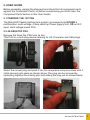
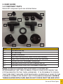
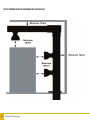
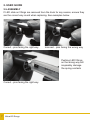
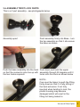
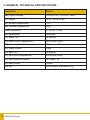
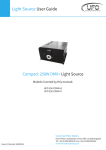
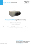
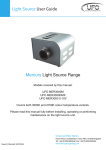
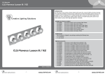
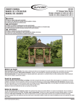
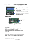
MetroLED User Guide
Models covered by this manual:
UFO MetroLED LW - Light Wand
UFO MetroLED LG - L Shaped Gantry
UFO MetroLED UG - U Shaped Gantry
UFO MetroLED FS - Free Standing Gantry
UFO MetroLED SP - Special Extrusion
Please read this manual fully before installing, operating or performing
maintenance on the system.
Universal Fibre Optics
Issue 2 | Revised: 22082013
Home Place | Coldstream | TD12 4DT | United Kingdom
Tel: +44 (0)1890 883416 | Fax: +44 (0)1890 883062
www.fibreopticlighting.com
1. INTRODUCTION
Thank you for purchasing this UFO MetroLED lighting system.
Please read these instructions fully before performing any installation,
operation or maintenance on the system, and before connecting to an electrical
supply.
The UFO MetroLED is a fully configurable LED track lighting system which has
been especially designed for ease-of-use and many installation environments.
Available in multiple configurations and with spotlight and linear lighting
modules both available with a choice of 3000K or 4000K light outputs,
If your system requires reconfiguring with new parts, please contact your UFO
sales representative for advice.
1
MetroLED Range
2. USER GUIDE
Before assembly, unpack the shipment and check that all component parts
against the Component Parts List before commencing your build (see the
Component Parts Section in this User Guide).
2.1 PREPARE THE 12V PSU
The MetroLED flexible lighting track system is powered from EITHER a
multifunction, multi-voltage, 4 Amp desk top Power Supply Unit, OR an IEC
input, multi-voltage boxed PSU.
2.2 4A DESKTOP PSU
Remove the Desk Top PSU from its box.
This PSU is a multi-plug device catering for UK, European and USA plugs.
Select the correct plug and push it into the receptacle and press down until it
clicks securely into place as shown above. The plug can be removed by
squeezing together the locking pins and sliding the plug out as shown below
Universal Fibre Optics
2
2. USER GUIDE
2.3 6A Desk Top PSU
Remove the PSU from its packing. This PSU is an IEC mains lead
device catering for UK, European and USA plugs. Plug the mains lead into the
IEC socket on the PSU – see below. The PSU is now ready for power.
DO NOT CONNECT PSU TO DIMMER UNTIL METROLED TRACK SYSTEM
IS FULLY ASSEMBLED AND THE DIMMER IS CONNECTED
2.4 COMPONENT PARTS
MetroLED component parts are detailed below.
1
2
3
4
5
6
7
8
3
Item
Description
1
3000K spotlight
2
3000K spotlight (note colour coded green dot on base)
3
4000K spotlight (no colour coding on base)
4
Wide angle trumpet and lens
5
Narrow angle trumpet and lens
6
Metal extrusion fitted with track insert
7
Plastic infill strip
8
Linear wash LED strip. 3000K or 4000K (3000K identified on base)
MetroLED Range
2. USER GUIDE
2.4 COMPONENT PARTS
MetroLED component parts are detailed below.
10
9
11
13
12
14
15
16
Item
Description
9
Extrusion end cap
10
45° end fitting
11
Power in connector
12
Left hand rotating corner (static corner also available)
13
Right hand rotating corner (static corner also available)
14
Corner 30m foot, unthreaded, screw plate
15
Standard round 42mm foot with threaded lock nut
16
Standard round 30mm foot, unthreaded, screw plate
NOTE: ROTATING ELBOWS ARE DESIGNED TO ROTATE BY
APPROXIMATELY 350º ONLY. A SMALL PLASTIC END STOP INSIDE THE
FITTING RESTRICTS THE TURN. HOWEVER, IT IS POSSIBLE TO FORCE
THE TURN PAST THIS END STOP WHICH WILL EVENTUALLY LEAD TO THE
FLEXIBLE CONNECTOR INSIDE THE FITTING BEING DAMAGED. ROTATE
THESE ELBOWS WITH CARE AND DO NOT FORCE PAST THE END STOP
Universal Fibre Optics
4
RECOMMENDED MINIMUM SPACING
5
MetroLED Range
2. USER GUIDE
2.5 ASSEMBLY - Slide on Parts
Most MetroLED systems are shipped either fully or partly assembled. All LEDs
should be already fitted to the 3 track extrusion. Assembly therefore will
generally involve fitting together extrusions. Gantry Legs will be marked “Left”
and “Right” to avoid confusion. CAUTION – fitting legs on the wrong side of a
gantry can result in a rotating joint being incorrectly turned and damaged.
Assemble the MetroLED system as per instructions below.
All plastic MetroLED components fit into the matching keyed sections of the
metal extrusions, either by sliding on, or by twisting and locking see 2.6
Push the fitting carefully but firmly into the extrusion taking great care to avoid
damaging adjacent LEDs. Make sure the plastic fitting is pushed fully home.
Universal Fibre Optics
6
2. USER GUIDE
2.5 ASSEMBLY
If LED slide on fittings are removed from the track for any reason, ensure they
are the correct way round when replacing. See examples below.
Correct - pins facing the right way
Incorrect - pins facing the wrong way
Pushing LED fittings
on the wrong way will
irreparably damage
the spring contacts
Correct - pins facing the right way
7
MetroLED Range
2.6 ASSEMBLY TWIST LOCK PARTS
This is a 2 part assembly - see photographs below
Assembly apart
Push assembly firmly into Base - turn
the top assembly so that it sits across
the base as shown
Push the base assembly into the track Push down and twist the upper
so that the connector pins line up with assembly through 90 degrees until it
locks onto the track as shown below
the two tracks required.
NOTE:Care must be taken to push the fitting
firmly down so that it is fully sitting in
the track extrusion. If not fully
inserted when twisting to lock, the
plastic housing may become
damaged which will result in the
fitting not being locked in.
Universal Fibre Optics
8
2. USER GUIDE
2.7 ELECTRICAL CONNECTIONS
There are 3 electrical connections required before connecting the system to the
mains – see drawing below
1.
2.
3.
9
Connect the extrusion power In connector track power cable to the
MetroLED dimmer ensuring correct wire colour codes
Connect the dimmer box and cable to MetroLED dimmer ensuring
correct wire colour codes
Plug the 5V DC jack plug into the input socket on the MetroLED
dimmer
MetroLED Range
2. USER GUIDE
2.7 ELECTRICAL CONNECTIONS
The MetroLED Dimmer unit has two +ve track outputs which are limited to 3
Amps – exceeding the load on either track will cause the overloaded track to
shut down and the overload indicator LED to illuminate.
Turn the dimming controls and check that the appropriate track dims and
brightens.
Plug the mains plug into the electrical supply socket. Switch on power the LEDs
on the track will illuminate. If no light is produced consult the
TROUBLESHOOTING section
2.7 MAINTENANCE
Please Note that a record of all maintenance MUST be kept in the table below,
indicating what maintenance was undertaken and when. This MUST be dated
for warranty purposes
Date
Maintenance Undertaken
Universal Fibre Optics 10
3. TROUBLESHOOTING
Problem
Probable Causes
Remedy
Main supply off
Check supply & reinstate
Loose main plugs
Check plugs
Loose DC output wire or
Unit is dead - no light connection
output from LED’s
PSU failed. Check output with
DVM
Check all connections
Replace PSU
Dimmer failed. Check input and
Replace dimmer
output with DVM
LEDs on one track
not working but no
MetroLED dimmer
overload LED
LEDs on one track
not working
MetroLED dimmer
overload LED
illuminated
LEDs on one part of
fixture/gantry not
working
LEDs won’t respond
to remote dimmer
controls
Poor light output on
individual LEDs
Loose DC output wire or connection to that particular track
Check all connections
Dimmer output channel failed.
Confirm by swapping output
wires over
Replace dimmer or move
channel wire of faulty channel
to working channel
Track overloaded
Disconnect +ve wire to overloaded track at dimmer. If LED
extinguishes, track is
overloaded. Remove LED
fittings until overload LED
extinguishes
MetroLED dimmer faulty
Disconnect +ve wire to
overloaded track at MetroLED
dimmer. If LED remains
illuminated replace dimmer
Bad connection on rotating
joint
Inspect joint, check connection
and ensure fully inserted
Rotating joint failed
Open joint and inspect wire
connections, if broken, replace
joint
Bad connection on dimmer
cable
Check connections
Faulty dimmer box
Replace dimmer box
Dimmer failed
Replace dimmer
LED failed
Replace individual LED
Please complete troubleshooting procedures before returning unit to us.
11 MetroLED Range
4. LED SPECIFICATIONS
Component
Variant
Nominal
Power
Working
Current
Notes
Spotlight
3000K
0.5W
100mA
Available in spot and
flood fitting
Spotlight
4000K
0.5W
100mA
Available in spot and
flood fitting
Linear Light 45mm
3000K
0.4W
80mA
Linear Light 45mm
4000K
0.4W
80mA
Linear Light 95mm
3000K
0.8W
160mA
Linear Light 95mm
4000K
0.8W
160mA
Linear Light 245mm
3000K
2.3W
460mA
Linear Light 245mm
4000K
2.3W
460mA
MetroLED Driver
Version 2
N/A
300mA per Overload indication and
channel
shut down
Universal Fibre Optics
12
4. GENERAL TECHNICAL SPECIFICATIONS
Description
Details
Main supply voltage
100-240V AC, 47-63 Hz, 0.58A
PSU output
5V DC, 4A or 5V 6A
Min. ambient temperature
-10°C
Max. ambient temperature
+45°C
Power connection
2.1 x 5.5 x 12mm
LED type/model
White light
LED linear CRI
85 (typical)
LED linear colour temperature
3000K and 4000K
LED linear optical efficiency
112 Lumen / W
LED linear current
10mA
LED spot CRI
95 (typical)
LED spot colour temperature
3000K and 4000K
LED spot optical efficiency
66 Lumen / W
LED spot current
100mA
LED life
50,000 hours in ambient 25°C
13 MetroLED Range
5. NOTES
Universal Fibre Optics 14
5. NOTES
15 MetroLED Range
5. NOTES
Universal Fibre Optics 16
5. NOTES
17 MetroLED Range
5. NOTES
Universal Fibre Optics 18
Universal Fibre Optics
Universal Fibre Optics
HomePlace,
Place Coldstream,
| Coldstream |TD12
TD12 4DT,
4DT | United
United Kingdom
Home
Kingdom
Tel:
883416
| Fax:
+44 +44
(0)1890
883062
Tel: +44
+44(0)1890
(0)1890
883416
| Fax:
(0)1890
883062
www.fibreopticlighting.com
www.universal-fibre-optics.com
| [email protected]