1
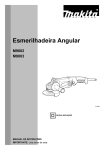
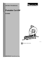
ENGLISH (Original instructions)
INSTRUCTION MANUAL
Portable Cut-Off
2414EN
013127
DOUBLE INSULATION
IMPORTANT: Read Before Using.
1
ENGLISH (Original instructions)
SPECIFICATIONS
Model
2414EN
Wheel diameter
355 mm
Hole diameter
25.4 mm
No load speed (min-1)
3,800
Dimensions (L x W x H)
With under cover
500 mm x 280 mm x 620 mm
Net weight
With European type safety
guard and under cover
17.6 kg
Safety class
/II
• Due to our continuing program of research and development, the specifications herein are subject to change without notice.
• Specifications may differ from country to country.
• Weight according to EPTA-Procedure 01/2003
END202-6
ENF100-1
For public low-voltage distribution systems of
between 220 V and 250 V.
Switching operations of electric apparatus cause
voltage fluctuations. The operation of this device under
unfavorable mains conditions can have adverse effects
to the operation of other equipment. With a mains
impedance equal or less than 0.21 Ohms it can be
presumed that there will be no negative effects. The
mains socket used for this device must be protected
with a fuse or protective circuit breaker having slow
tripping characteristics.
Symbols
The following show the symbols used for the equipment.
Be sure that you understand their meaning before use.
・ Read instruction manual.
・
DOUBLE INSULATION
・
Wear safety glasses.
・
Only for EU countries
Do not dispose of electric equipment
together
with
household
waste
material!
In observance of European Directive
2002/96/EC on waste electric and
electronic
equipment
and
its
implementation in accordance with
national law, electric equipment that
have reached the end of their life must
be collected separately and returned to
an
environmentally
compatible
recycling facility.
ENG905-1
Noise
The typical A-weighted
according to EN61029:
noise
level
determined
Sound pressure level (LpA) : 102 dB(A)
Sound power level (LWA) : 112 dB(A)
Uncertainty (K) : 3 dB(A)
Wear ear protection
ENG900-1
Vibration
The vibration total value (tri-axial
determined according to EN61029:
ENE007-3
Intended use
The tool is intended for cutting in ferrous materials with
appropriate abrasive cut-off wheel. Follow all laws and
regulations regarding dust and work area health and
safety in your country.
vector
sum)
Vibration emission (ah) : 3.5 m/s2
Uncertainty (K) : 1.5 m/s2
ENG901-1
ENF002-2
•
Power supply
The tool should be connected only to a power supply of
the same voltage as indicated on the nameplate, and
can only be operated on single-phase AC supply. They
are double-insulated and can, therefore, also be used
from sockets without earth wire.
•
•
2
The declared vibration emission value has been
measured in accordance with the standard test
method and may be used for comparing one tool
with another.
The declared vibration emission value may also be
used in a preliminary assessment of exposure.
WARNING:
The vibration emission during actual use of the
power tool can differ from the declared emission
value depending on the ways in which the tool is
used.
Be sure to identify safety measures to protect the
operator that are based on an estimation of
exposure in the actual conditions of use (taking
account of all parts of the operating cycle such as
the times when the tool is switched off and when it
is running idle in addition to the trigger time).
2.
ENH003-14
4.
We Makita Corporation as the responsible
manufacturer declare that the following Makita
machine(s):
Designation of Machine:
Portable Cut-Off
Model No./ Type: 2414EN
are of series production and
Conforms to the following European Directives:
2006/42/EC
And are manufactured in accordance with the following
standards or standardised documents:
EN61029
The technical documentation is kept by:
Makita International Europe Ltd.
Technical Department,
Michigan Drive, Tongwell,
Milton Keynes, Bucks MK15 8JD, England
5.
•
3.
For European countries only
EC Declaration of Conformity
6.
7.
8.
9.
27.2.2012
10.
000230
Tomoyasu Kato
Director
Makita Corporation
3-11-8, Sumiyoshi-cho,
Anjo, Aichi, 446-8502, JAPAN
11.
12.
ENA001-2
SAFETY INSTRUCTIONS
WARNING! When using electric tools, basic safety
precautions, including the following, should always
be followed to reduce the risk of fire, electric shock
and personal injury. Read all these instructions
before operating this product and save these
instructions.
13.
14.
For safe operations:
1.
Keep work area clean.
Cluttered areas and benches invite injuries.
3
Consider work area environment.
Do not expose power tools to rain. Do not use
power tools in damp or wet locations. Keep work
area well lit. Do not use power tools where there
is risk to cause fire or explosion.
Guard against electric shock.
Avoid body contact with earthed or grounded
surfaces
(e.g.
pipes,
radiators,
ranges,
refrigerators).
Keep children away.
Do not let visitors touch the tool or extension cord.
All visitors should be kept away from work area.
Store idle tools.
When not in use, tools should be stored in a dry,
high or locked up place, out of reach of children.
Do not force the tool.
It will do the job better and safer at the rate for
which it was intended.
Use the right tool.
Do not force small tools or attachments to do the
job of a heavy duty tool. Do not use tools for
purposes not intended; for example, do not use
circular saws to cut tree limbs or logs.
Dress properly.
Do not wear loose clothing or jewellery, they can
be caught in moving parts. Rubber gloves and
non-skid footwear are recommended when
working outdoors. Wear protecting hair covering
to contain long hair.
Use safety glasses and hearing protection.
Also use face or dust mask if the cutting
operation is dusty.
Connect dust extraction equipment.
If devices are provided for the connection of dust
extraction and collection facilities ensure these
are connected and properly used.
Do not abuse the cord.
Never carry the tool by the cord or yank it to
disconnect it from the socket. Keep the cord away
from heat, oil and sharp edges.
Secure work.
Use clamps or a vice to hold the work. It is safer
than using your hand and it frees both hands to
operate the tool.
Do not overreach.
Keep proper footing and balance at all times.
Maintain tools with care.
Keep cutting tools sharp and clean for better and
safer performance. Follow instructions for
lubrication and changing accessories. Inspect tool
cord periodically and if damaged have it repaired
by an authorized service facility. Inspect
extension cords periodically and replace, if
damaged. Keep handles dry, clean and free from
oil and grease.
15.
16.
17.
18.
19.
20.
21.
22.
Disconnect tools.
When not in use, before servicing and when
changing accessories such as blades, bits and
cutters.
Remove adjusting keys and wrenches.
Form the habit of checking to see that keys and
adjusting wrenches are removed from the tool
before turning it on.
Avoid unintentional starting.
Do not carry a plugged-in tool with a finger on the
switch. Ensure switch is off when plugging in.
Use outdoor extension leads.
When tool is used outdoors, use only extension
cords intended for outdoor use.
Stay alert.
Watch what you are doing. Use common sense.
Do not operate tool when you are tired.
Check damaged parts.
Before further use of the tool, a guard or other
part that is damaged should be carefully checked
to determine that it will operate properly and
perform its intended function. Check for alignment
of moving parts, free running of moving parts,
breakage of parts, mounting and any other
conditions that may affect its operation. A guard
or other part that is damaged should be properly
repaired or replaced by an authorized service
center unless otherwise indicated in this
instruction manual. Have defective switches
replaced by an authorized service facility. Do not
use the tool if the switch does not turn it on and
off.
Warning.
The use of any accessory or attachment, other
than those recommended in this instruction
manual or the catalog, may present a risk of
personal injury.
Have your tool repaired by a qualified person.
This electric tool is in accordance with the
relevant safety requirements. Repairs should only
be carried out by qualified persons using original
spare parts, otherwise this may result in
considerable danger to the user.
3.
4.
5.
6.
7.
8.
9.
10.
11.
12.
13.
14.
15.
16.
17.
18.
19.
ENB066-2
ADDITIONAL SAFETY RULES
FOR TOOL
1.
2.
only fiberglass-reinforced cut-off wheels.
Check the wheel carefully for cracks or
damage before operation. Replace cracked or
damaged wheel immediately.
Secure the wheel carefully.
Use only flanges specified for this tool.
Be careful not to damage the spindle, flanges
(especially the installing surface) or bolt, or
the wheel itself might break.
Keep guards in place and in working order.
Hold the handle firmly.
Keep hands away from rotating parts.
Make sure the wheel is not contacting the
work-piece before the switch is turned on.
Before using the tool on an actual workpiece,
let it simply run for several minutes first.
Watch for flutter or excessive vibration that
might be caused by poor installation or a
poorly balanced wheel.
Watch out for flying sparks when operating.
They can cause injury or ignite combustible
materials.
Remove material or debris from the area that
might be ignited by sparks. Be sure that
others are not in the path of the sparks. Keep
a proper, charged fire extinguisher closely
available.
Use the cutting edge of the wheel only. Never
use side surface.
If the wheel stops during the operation, makes
an odd noise or begins to vibrate, switch off
the tool immediately.
Always switch off and wait for the wheel to
come to a complete stop before removing,
securing workpiece, working vise, changing
work position, angle or the wheel itself.
Do not touch the workpiece immediately after
operation; it is extremely hot and could burn
your skin.
Store wheels in a dry location only.
Ensure that ventilation openings are kept
clear when working in dusty conditions. If it
should become necessary to clear dust, first
disconnect the tool from the mains supply
( use non metallic objects ) and avoid
damaging internal parts.
SAVE THESE INSTRUCTIONS.
Wear protective glasses. Also wear hearing
protection during extended periods of
operation.
Use only wheels recommended by the
manufacturer which have a maximum
operating speed at least as high as "No Load
RPM" marked on the tool’s nameplate. Use
4
Spark guard
INSTALLATION
Securing cut-off
1
2
1. Base
2. Bolt holes
1
1. Screw
2. Spark guard
013130
The spark guard is factory-installed with its lower edge
contacting the base. Operating the tool in this position
will cause many sparks to fly around. Loosen the screw
and adjust the spark guard to a position at which
minimum sparks will fly around.
2
013128
This tool should be bolted with two bolts to a level and
stable surface using the bolt holes provided in the tool's
base. This will help prevent tipping and possible
personal injury.
Interval between vise and guide plate
FUNCTIONAL DESCRIPTION
•
1
2
CAUTION:
Always be sure that the tool is switched off and
unplugged before adjusting or checking function
on the tool.
1. Socket wrench
2. Guide plate
3. Move
4. Hex bolts
3
Switch action
4
1
2
013131
1. Lock-off button
2. Switch trigger
The original spacing or interval between the vise and
the guide plate is 0 - 170 mm. If your work requires
wider spacing or interval, proceed as follows to change
the spacing or interval.
Remove the two hex bolts which secure the guide plate.
Move the guide plate as shown in the figure and secure
it using the hex bolts. The following interval settings are
possible:
35 - 205 mm
70 - 240 mm
013129
CAUTION:
Before plugging in the tool, always check to see
that the switch trigger actuates properly and
returns to the "OFF" position when released.
For tool with lock-off button
To prevent the switch trigger from being accidentally
pulled, a lock-off button is provided.
To start the tool, depress the lock-off button and pull the
switch trigger. Release the switch trigger to stop.
•
003759
•
5
CAUTION:
Remember that narrow workpieces may not be
secured safely when using the two, wider interval
settings.
Setting for desired cutting angle
1. Socket wrench
2. Guide plate
3. Hex bolts
1
2
013148
3
013132
To change the cutting angle, follow the procedure
below:
1.
Loosen the two hex bolts.
2.
Set the guide plate to the desired angle (0° - 45°).
3.
For more accurate angle, use a protractor or
triangle ruler. Keep the handle down so that the
cut-off wheel extends into the base. At the same
time, adjust the angle between the guide plate
and the cut-off wheel with a protractor or triangle
ruler.
4.
Tighten the hex bolts securely. At this time, make
sure that the guide rule does not move.
5.
Check the angle again.
•
013147
To remove the wheel, loosen the clamping screw, hold
the safety guide by both hands and raise it, then slide
the safety guide towards yourself.
1. Shaft lock
2. Socket wrench
1
CAUTION:
Never perform miter cuts when the guide plate is
set at the 35 - 205 mm or 70 - 240 mm position.
2
NOTE:
•
The scale on the guide plate is only a rough
indication.
013146
ASSEMBLY
•
Press the shaft lock so that the wheel cannot revolve
and use the socket wrench to loosen the hex bolt by
turning it counterclockwise. Then remove the hex bolt,
outer flange and wheel. (Note: Do not remove the inner
flange, ring and O-ring.)
To install the wheel, follow the removal procedures in
reverse.
CAUTION:
Always be sure that the tool is switched off and
unplugged before carrying out any work on the
tool.
Removing or installing cut-off wheel
1
1. Clamping screw
2. Safety guide
2
7
2
1
3
6
4
1. O-ring
2. Inner flange
3. Ring
4. Spindle
5. Cut-off wheel
6. Outer flange
7. Hex bolt
5
003762
013182
•
6
CAUTION:
Be sure to tighten the hex bolt securely.
Insufficient tightening of the hex bolt may result in
severe injury. Use the socket wrench provided to
help assure proper tightening.
•
•
Always use only the proper inner and outer
flanges which are provided with this tool.
Always lower the safety guard after replacing the
wheel.
Securing workpiece
5
3
4
1. Vise plate
2. Vise nut
3. Vise handle
1
2
1. Guide plate
2. Straight piece of
wood (Spacer)
3. Over 45 mm
long
4. Over 65 mm
long
5. Over 190 mm
long
1
2
005342
If you use a spacer block which is slightly narrower than
the workpiece as shown in the figure, you can also
utilize the wheel economically.
3
1
013135
By turning the vise handle counterclockwise and then
flipping the vise nut to the back, the vise is released
from the shaft threads and can be moved rapidly in and
out. To grip workpieces, push the vise handle until the
vise plate contacts the workpiece. Flip the vise nut to
the front and then turn the vise handle clockwise to
securely retain the workpiece.
2
3
5
1. Diameter of
workpiece
2. Guide plate
3. Spacer block
4. Width of spacer
block
5. Vise
4
003766
Long workpieces must be supported by blocks of nonflammable material on either side so that it will be level
with the base top.
CAUTION:
Always set the vise nut to the front fully when
securing the workpiece. Failure to do so may
result in insufficient securing of the workpiece.
This could cause the workpiece to be ejected or
cause a dangerous breakage of the wheel.
When the cut-off wheel has worn down considerably,
use a spacer block of sturdy, non-flammable material
behind the workpiece as shown in the figure. You can
more efficiently utilize the worn wheel by using the mid
point on the periphery of the wheel to cut the workpiece.
•
1. Blocks
1
013137
1. Spacer block
OPERATION
1
Hold the handle firmly. Switch on the tool and wait until
the wheel attains full speed before lowering gently into the
cut. When the wheel contacts the workpiece, gradually
bear down on the handle to perform the cut. When the cut
is completed, switch off the tool and WAIT UNTIL THE
WHEEL HAS COME TO A COMPLETE STOP before
returning the handle to the fully elevated position.
013136
When cutting workpieces over 65 mm wide at an angle,
attach a straight piece of wood (spacer) over 190 mm
long x 45 mm wide to the guide plate as shown in the
figure. Attach this spacer with screws through the holes
in the guide plate.
•
7
CAUTION:
Proper handle pressure during cutting and
maximum cutting efficiency can be determined by
the amount of sparks that is produced while
cutting. Your pressure on the handle should be
adjusted to produce the maximum amount of
sparks. Do not force the cut by applying excessive
pressure on the handle. Reduced cutting efficiency,
premature wheel wear, as well as, possible
damage to the tool, cut-off wheel or workpiece
may result.
Fold down the tool head to the position where you can
attach the chain to the hook on the handle.
Cutting capacity
MAINTENANCE
Max. cutting capacity varies depending upon the cutting
angle and workpiece shape. Applicable wheel diameter:
355 mm
CAUTION:
Always be sure that the tool is switched off and
unplugged before attempting to perform inspection
or maintenance.
•
Never use gasoline, benzine, thinner, alcohol or
the like. Discoloration, deformation or cracks may
result.
The tool and its air vents have to be kept clean.
Regularly clean the tool's air vents or whenever the
vents start to become obstructed.
•
Workpiece
shape
Cutting
angle
90°
115 mm
119 mm
45°
115 mm
106 mm
Replacing carbon brushes
Workpiece
shape
1. Limit mark
Cutting
angle
90°
115mm x 130mm
102 mm × 194 mm
70 mm × 233 mm
137 mm
45°
115mm x 103mm
100 mm
1
001145
005270
Remove and check the carbon brushes regularly.
Replace when they wear down to the limit mark. Keep
the carbon brushes clean and free to slip in the holders.
Both carbon brushes should be replaced at the same
time. Use only identical carbon brushes.
Use a screwdriver to remove the brush holder caps.
Take out the worn carbon brushes, insert the new ones
and secure the brush holder caps.
For tools with the under cover
1. Under cover
2. Wing bolt
1
1. Screwdriver
2. Brush holder
cap
2
005272
To remove the collected dust from the under cover,
place the tool with its side up and pull the under cover
open after removing the wing bolt as shown in the figure.
Be sure to close and secure the under cover with the
wing bolt after the removal of dust.
1
2
Carrying tool
013139
To maintain product SAFETY and RELIABILITY, repairs,
any other maintenance or adjustment should be
performed by Makita Authorized Service Centers,
always using Makita replacement parts.
013138
8
OPTIONAL ACCESSORIES
CAUTION:
These
accessories
or
attachments
are
recommended for use with your Makita tool
specified in this manual. The use of any other
accessories or attachments might present a risk of
injury to persons. Only use accessory or
attachment for its stated purpose.
If you need any assistance for more details regarding
these accessories, ask your local Makita Service Center.
•
Abrasive cut-off wheels
•
Socket wrench 17
•
NOTE:
•
Some items in the list may be included in the tool
package as standard accessories. They may differ
from country to country.
9
10
11
Makita Corporation
Anjo, Aichi, Japan
885152-222
12
www.makita.com