1
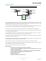
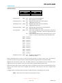
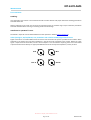
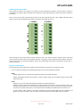
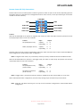
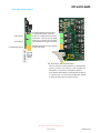
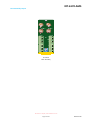
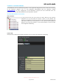
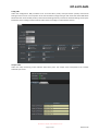
IRT-6170-AMS
3G/HD/SD-SDI, ASI, G.703, Video, Audio Relay Changeover Switch
User Manual
IRT Electronics Pty Ltd | www.irtelectronics.com
Page 1 of 18
Revision 00
IRT-6170-AMS
3G/HD/SD-SDI, ASI, G.703, Video, Audio Relay Changeover Switch
Revision History:
Revision
00
Date
16/12/2013
By
AL
Change Description
Original Issue.
Applicable to:
Firmware ≥
Revision 1.0
IRT Electronics Pty Ltd | www.irtelectronics.com
Page 2 of 18
Revision 00
IRT-6170-AMS
USER MANUAL
Table of Contents:
Section
Page
Revision History
Operational Safety
openGear® Introduction
General Description
Technical Specifications
Configuration
DIP Switch Settings
Installation
Video Signal Connections
Audio Signal Connections
Output Terminations
Remote Control & Tally Connections
Front Edge Switch Locations
Rear Assembly Layout
Operation
Local Control
Remote Control
Magnetic Latch Mode
Switch to ground operation
Switch to open circuit operation
Toggle Mode
Switch to ground operation
Switch to open circuit operation
DashBoard™ Software Control
IRT-6170-AMS DashBoard™ Screenshots
Maintenance & Storage
Warranty & Service
2
4
4
5
6
7
7
8
8
9
9
10
12
13
14
14
15
15
15
15
15
15
15
16
16
18
18
This instruction book applies to units fitted with firmware ≥ Revision 1.0.
IRT Electronics Pty Ltd | www.irtelectronics.com
Page 3 of 18
Revision 00
IRT-6170-AMS
OPERATIONAL SAFETY
WARNING
Operation of electronic equipment involves the use of voltages and currents that
may be dangerous to human life. Note that under certain conditions dangerous
potentials may exist in some circuits when power controls are in the OFF position.
Maintenance personnel should observe all safety regulations.
Do not make any adjustments inside equipment with power ON unless proper
precautions are observed. All internal adjustments should only be made by suitably
qualified personnel. All operational adjustments are available externally without
the need for removing covers or use of extender cards.
openGear® INTRODUCTION
Developed by Ross Video, openGear® is a standard where various manufacturers can design their equipment to fit
a common frame allowing the end user to mix and match the various openGear® cards available in the market
place together in one frame. This allows a single frame to be used instead of multiple different vendor’s frames
that each would otherwise be using their own proprietary standard.
A simple to use monitoring and control software called DashBoard™ is a free program downloadable from the
openGear® website (www.opengear.tv) that allows the user to remotely monitor and control an openGear® type
card fitted within an openGear® frame that meets the openGear® standard for DashBoard™ control. A link is also
supplied via the IRT Electronics website (www.irtelectronics.com) under the openGear® navigation section.
IRT Electronics’ openGear® cards are designed to meet the openGear® standard for mounting within the
openGear® OG3-FR frame and its earlier version DFR-8300 frame, and is fully compliant with DashBoard™ control.
The openGear® frame manual, DashBoard™ control software and information regarding the frame’s power
supplies, controller card and frame accessories are available for download at the openGear® website.
The term openGear® is a registered trade mark of Ross Video Limited.
DashBoard software Control™ is a trade mark of Ross Video Limited.
IRT Electronics Pty Ltd | www.irtelectronics.com
Page 4 of 18
Revision 00
IRT-6170-AMS
GENERAL DESCRIPTION
BLOCK DIAGRAM IRT-6170-AMS SIGNAL PATH
VIDEO A I/P
VIDEO B I/P
VIDEO A
O/P
VIDEO B
O/P
AUDIO A (L) I/P
AUDIO A (L) O/P
AUDIO B (L) O/P
AUDIO B (L) I/P
AUDIO A (R) I/P
AUDIO A (R) O/P
AUDIO B (R) O/P
AUDIO B (R) I/P
FPGA
CONTROL
Video Tally
Audio Tally
Video Set
Video Reset
Audio Set
Audio Reset
The IRT-6170-AMS consists of one “video” and two “balanced audio” switches arranged as a changeover set with
two inputs and two outputs. No terminations are provided on the board allowing the switcher to be used in a wide
variety of applications and with signals of various types and impedances.
The “video” path uses enhanced performance relays to provide switching capabilities for high-speed data signals
up to 2.97 Gb/s and may be used with analogue video, 3G/HD/SD/ASI or G.703 data signals.
The “audio” path may be used for balanced or unbalanced audio or control signals (RS232, RS422, RS485 etc).
The magnetic latching characteristic of the high performance relays allows momentary control and also provides
for no change of path during power loss.
The IRT-6170-AMS is ideally suited to applications where a simple choice between two inputs or outputs is
required and may be easily driven by detector circuits for automatic path selection.
Local switching is possible using front edge push button switches. Remote switching is possible using external
normally open or normally closed alarms.
Front edge switches use a small delay to avoid accidental switching if bumped. After a period of about a minute,
the IRT-6170-AMS automatically switches back into remote mode.
Remote indication of tally status is provided for integration into central alarm and monitoring systems.
The IRT-6170-AMS is designed to fit the openGear® standard 2RU frames which allow a mixture of cards from
various manufacturers to be mounted within the same frame.
The DashBoard™ control software is available as a free download.
Standard features:
• One video and two audio changeover switches in one package.
• Video path suitable for 3G/HD/SD-SDI, Analogue video, ASI, G.703 signals @ 2, 8, 34, 45, 144,
155 Mb/s, and unbalanced AES.
• Audio path suitable for 2 balanced, or 4 unbalanced, audio or data signals, and balanced AES.
• Married or independent operation.Momentary Set/Reset control.
• No path change on power fail.
• Local or remote control.
• DashBoard™ software monitoring and control.
IRT Electronics Pty Ltd | www.irtelectronics.com
Page 5 of 18
Revision 00
IRT-6170-AMS
TECHNICAL SPECIFICATIONS
Video Signal path:
Signal types
Impedance
Switching characteristic
Video crosstalk between channels
Frequency response
3G-SDI/HD-SDI/SD-SDI/ASI/G.703/Video/unbalanced AES.
Non-terminating, designed for 75 Ω use.
Magnetic latching 4 port changeover relay.
< -75 dB to 10 MHz (measured input terminated by 75 Ω);
< -45 dB to 270 MHz;
< -40 dB to 1.5 GHz;
< -25 dB to 3.0 GHz.
+0/-1.5 dB 0 Hz to 3.0 GHz.
Audio/Low speed Data:
Audio Crosstalk
< -90 dB (20 Hz - 20 kHz, input terminated by 600 Ω).
Control:
Mode
Gnd
Video SET
Video RESET
Audio SET
Audio RESET
NOTE:
Tally
Video Tally
Audio Tally
Front edge switches
Momentary ground or open circuit, switch selectable.
Pins 1 & 2.
Pin 3 (Video Standby).
Pin 4 (Video Main).
Pin 5 (Audio Standby).
Pin 6 (Audio Main).
Separate Audio & Video controls, or
Audio follows Video, switch selectable.
Non-momentary contacts required in Toggle modes.
Switch to Ground – Standby; Switch to Open Circuit - Main.
Pin 7.
Pin 8.
Momentary illuminated push button.
Automatic remote default setting after about a minute.
Connectors:
Video
Audio
Control & Tally
BNC.
5 pin Phoenix pluggable screw block.
8 pin HE-14 IDC.
Relay:
Contact rating
30 Vdc – 0.5 A.
Power Requirements:
Voltage
Power consumption
+ 12 Vdc.
< 4VA.
Other:
Temperature range
0 - 50° C ambient.
Mechanical
Suitable for mounting in an openGear® 2RU rack chassis.
Dimensions (openGear® standard) 33.6 mm x 2U x 325 mm;
Supplied accessories
Rear connector assembly with matching connectors for control input and tally
outputs.
Ordering
IRT-6170-AMS
IRT-6170-AMS, programmed with DashBoard™ control.
NOTE: Main:
Standby:
IN A to OUT A, IN B to OUT B (green switch indication);
IN A to OUT B, IN B to OUT A (orange switch indication).
Due to our policy of continuing development, these specifications are subject to change without notice.
IRT Electronics Pty Ltd | www.irtelectronics.com
Page 6 of 18
Revision 00
IRT-6170-AMS
CONFIGURATION
DIP Switch settings:
DIP
ON
DIP
SW1
ON
1 2 3 4 5 6 7 8
1 2 3 4 5 6 7 8
SW2
Remote Control:
SW1-1 OFF
ON
Switch to Ground control (Default).
Switch to Open Circuit control.
Video Relay Control
SW1-2 OFF
ON
Magnetic Latch Video relay control (Default).
Toggle Video relay control.
Audio Relay Control
SW1-3 OFF
ON
Magnetic Latch Audio relay control (Default).
Toggle Audio relay control.
Audio follows Video
SW1-4 OFF
ON
Separate Audio and Video relay controls (Default).
Audio follows Video relay control.
Local to Remote
SW1-5 OFF
Front Panel Local/Remote switch automatically reverts from
Local to Remote mode after a period of approximately one
minute (Default).
Front Panel Local/Remote switch permanently stays in its set
position - i.e. does not automatically revert to Remote mode.
ON
SW1-6 Not Used.
SW1-7 Not Used.
SW1-8 Not Used.
SW2-1 Not Used.
SW2-2 Not Used.
SW2-3 Not Used.
SW2-4 Not Used.
SW2-5 Not Used.
SW2-6 Not Used.
SW2-7 Not Used.
DashBoard™ Control SW2-8 OFF
ON
DIP switch control (Default).
DashBoard™ control.
Remote switching control is either by switch to ground operation, or switch to open circuit. This allows for
connection to either alarm type condition of external equipment being used to drive the IRT-6170-AMS.
Magnetic latch relay control needs a ‘SET’ and ‘RESET’ operation to switch between the two relay states, whilst
toggle relay control only requires a ‘SET’ and ‘removal of SET’ to switch between the two states.
With Audio follows Video control, only the video control is needed as the audio relays track what the video relay is
doing. If video relay has been set for magnetic latch operation, audio relays are also set for magnetic latch
operation.
In Toggle mode, a permanent contact (or break) is needed for the SET control. RESET pin is not used.
NOTE: Open circuit control implies removing a ground contact.
IRT Electronics Pty Ltd | www.irtelectronics.com
Page 7 of 18
Revision 00
IRT-6170-AMS
INSTALLATION
Pre-installation:
Handling:
This equipment may contain or be connected to static sensitive devices and proper static free handling precautions
should be observed.
Where individual circuit cards are stored, they should be placed in antistatic bags. Proper antistatic procedures
should be followed when inserting or removing cards from these bags.
Installation in openGear® frame:
See details in separate manual downloadable from the openGear® website (www.opengear.tv).
Video (analogue, 3G/HD/SD-SDI, ASI, G.703 data and unbalanced AES) Signal Connections:
Signal connections are made to BNC coaxial connectors. No termination of inputs is provided on the module. When
switched to the output the input load impedance is that of the load connected to the output. Where the input
signal is required to be terminated, and one of the outputs is not connected to anything, then this unconnected
output should be terminated by an appropriate BNC terminator of the required impedance, usually 75 Ohm.
IN A
IN B
OUT A
OUT B
IRT Electronics Pty Ltd | www.irtelectronics.com
Page 8 of 18
Revision 00
IRT-6170-AMS
Audio Signal Connections:
Audio signal connections are made to 5-pin plug in screw terminating connectors. No termination of inputs is
provided on the module. When switched to the output the input load impedance is that of the load connected to
the output.
There are four 5-pin audio connectors (IN A / OUT A Left, IN B / OUT B Left, IN A / OUT A Right and IN B / OUT B
Right). Common Ground between IN and OUT is shared via the middle pin (pin 3).
OUT A
IN B
+ - G + -
OUT B
R AUDIO
+ - G + -
IN A
L AUDIO
When wiring, be sure to keep phase of audio cables the same. The above connector will take either a balanced
input, balanced output audio (or data (RS-232, RS-422, etc.)) signal, or two unbalanced audio signals, where the
ground connectors are commoned together and the two unbalanced audio signals connected to each of the +/phase connections.
Output Terminations:
No terminations are provided on the module so that the switcher can function in changeover mode.
For 2 x 1 switcher applications the following terminations are recommended be installed:
Video:
Output A (Main) only is used and should be terminated at connected equipment.
Output B (Standby) should be terminated in 75Ω (or 50Ω if being used for 50Ω RF signals) using a BNC
termination plug.
Audio:
Outputs A only are used and should be terminated at connected equipment.
Output B may be terminated if desired by connecting termination resistors to the connector on the rear
assembly of the module. The resistor values should be chosen to match the characteristic impedance of the
rest of the connected audio system. For example for balanced 600Ω, two 300Ω resistors should be used.
In most modern audio systems a low output impedance of approximately 40Ω and input impedances of
greater than 10 kΩ are used. If this is the case no termination of the unused audio output is required.
IRT Electronics Pty Ltd | www.irtelectronics.com
Page 9 of 18
Revision 00
IRT-6170-AMS
Remote Control & Tally Connections:
Remote switch control is made by either a switch to ground or switch to open circuit contact, depending upon the
DIP switch settings as described in the Configuration section of this manual, on the 8-pin HE-14 type of connector
located on the rear assembly:
CONTROL
GND
Video SET
Audio SET
Video Tally
1
2
3
4
5
6
7
8
GND
Video RESET
Audio RESET
Audio Tally
Control:
With the IRT-6170-AMS set to operate in magnetic latch mode, the video and audio relays will operate and cause
the input/output states to cross over as follows:
Control
SET (Gnd/Open Circuit)
Input
Output
A (Main)
↔ B
B (Standby) ↔ A
RESET (Gnd/Open Circuit)
A (Main)
↔
B (Standby) ↔
A
B
Separate video and audio controls independently switch the video and audio relays unless the IRT-6170-AMS has
been configured for “Audio follows Video” configuration.
Note: In magnetic latch mode, only a momentary contact (or break) is needed for the SET and RESET controls.
With the IRT-6170-AMS set to operate in the toggle mode, the video an audio relays will operate and cause the
input/output states to cross over as follows:
Control
SET (Gnd/Open Circuit)
(make contact)
Input
Output
A (Main)
↔ B
B (Standby) ↔ A
SET (Open Circuit/Gnd)
(break contact)
A (Main)
↔
B (Standby) ↔
A
B
Note: In toggle mode, a permanent contact (or break) is needed for the SET control. RESET pin is not used.
With “Audio follows Video” configuration, the audio relays change as per the video relay controls above.
Note: Audio SET and RESET controls (pins 5 and 6) are not used when configured for “Audio follows Video”
configuration.
IRT Electronics Pty Ltd | www.irtelectronics.com
Page 10 of 18
Revision 00
IRT-6170-AMS
Tally:
Switch status (Tally) is made by relay contacts switching to ground on pins 7 (video) and 8 (audio) of the 8-pin
HE-14 control connector.
A switch to ground contact represents that the Video and/or Audio relays are in a STANDBY (SET) position.
STANDBY status is represented as:
Input A (Main) to Output B; and
Input B (Standby) to Output A.
MAIN status is represented as:
Input A (Main) to Output A; and
Input B (Standby) to Output B.
IRT Electronics Pty Ltd | www.irtelectronics.com
Page 11 of 18
Revision 00
IRT-6170-AMS
Front Edge Switch Locations
Audio Switch
Front Edge Switches and Indicators
In this situation both Video and
Audio are in MAIN position (Green):
Video I/P A → O/P A, I/P B → O/P B,
Audio I/P A → O/P A, I/P B → O/P B
(as indicated by the green switches).
Local/Remote Switch
Local/Remote Switch is in the Remote
position (Orange).
Video Switch
IRT-6170-AMS
SW_boot switch: Default Reset Switch.
User set names and switch position are stored within
memory so that in the event of a loss of power this
information is restored on resumption of power.
If the default Reset Switch is pressed whilst powering
or inserting the card, the IRT-6170-AMS will default
to factory preset names and input position.
IRT Electronics Pty Ltd | www.irtelectronics.com
Page 12 of 18
Revision 00
IRT-6170-AMS
Rear Assembly Layout
Standard
Rear Assembly
IRT Electronics Pty Ltd | www.irtelectronics.com
Page 13 of 18
Revision 00
IRT-6170-AMS
OPERATION
The IRT-6170-AMS can be used for a MAIN / STANDBY changeover switch, or a 2x1 switcher, application.
Switcher control is done either locally via the front edge pushbutton switches, remotely by external
signals / alarms connected via the 8-pin HE-14 type of control connector on the rear assembly, or via DashBoard™
software control.
Local Control:
There are three front panel momentary pushbuttons marked designated in order from top to
bottom as VIDEO MAIN / STANDBY, AUDIO MAIN / STANDBY and LOCAL / REMOTE.
The LOCAL / REMOTE switch switches between front switch local control and remote control via the
8-pin HE-14 type of control connector on the rear assembly. The default state is in the remote
(orange) setting. To switch to front panel local control, press this button and hold for approximately
a second. Switch colour then changes to green indicating that the VIDEO and AUDIO MAIN /
STANDBY switches are now operational. Unless DIP switch SW1-5 is set to ON, after a period of
about a minute the LOCAL / REMOTE switch automatically reverts back to the remote setting.
The VIDEO and AUDIO MAIN / STANDBY switches independently switch the video and audio relays
between MAIN (Input A goes to Output A, Input B goes to Output B) and STANDBY (Input B goes to
Output A, Input A goes to Output B) positions. To activate, press and hold for approximately a
second. Switch colour changes between green (MAIN) and orange (STANDBY) to indicate which
position the changeover relays are in.
IRT-6170-AMS
If, however, Audio relays have been set to follow the Video relay, either by the SW1-4 DIP switch
position or via the DashBoard™ setting, Audio relays will follow that of the Video relay state and the
AUDIO MAIN / STANDBY switch will not function except to indicate the same state as the VIDEO
MAIN / STANDBY switch position.
IRT Electronics Pty Ltd | www.irtelectronics.com
Page 14 of 18
Revision 00
IRT-6170-AMS
Remote Control:
Magnetic Latch Mode:
With SW1-2 OFF, the video SET (pin 3) and video RESET (pin 4) of the HE-14 type of connector on the rear
assembly controls the operation of the video magnetic latch mode of operation.
With SW1-3 OFF, the audio SET (pin 5) and audio RESET (pin 6) of the HE-14 type of connector on the rear
assembly controls the operation of the audio magnetic latch mode of operation.
If switch SW1-4 has been set to ON so that the audio relays operation follows that of the video relay operation,
then the audio SET and audio RESET pins are non-functional.
Switch to ground operation:
If the IRT-6170-AMS has been set to switch to ground operation with the DIP switch SW1-1 OFF, provided
the RESET pins aren’t already being held to ground, momentarily grounding the SET pins will select Input A
(Main) to Output B, and Input B (Standby) to Output A.
Provided the SET pins aren’t already being held to ground, momentarily grounding the RESET pins will select
Input A (Main) to Output A, and Input B (Standby) to Output B.
Switch to open circuit operation:
If the IRT-6170-AMS has been set to switch to open circuit operation with the DIP switch SW1-1 ON,
provided the RESET pins aren’t already being held open circuit, momentarily open circuiting the SET pins will
select Input A (Main) to Output B, and Input B (Standby) to Output A.
Provided the SET pins aren’t already being held to open circuit, momentarily open circuiting the RESET pins
will select Input A (Main) to Output A, and Input B (Standby) to Output B.
Toggle Mode:
With SW1-2 ON, the video SET (pin 3) control operates in the video toggle mode of operation. The video RESET
(pin 4) pin has no effect on the video relay control whilst in the toggle mode of operation.
With SW1-3 ON, the audio SET (pin 5) control operates in the video toggle mode of operation. The audio RESET
(pin 6) pin has no effect on the audio relay control whilst in the toggle mode of operation.
If switch SW1-4 has been set to ON so that the audio relays operation follows that of the video relay operation,
the audio SET pin is non-functional.
Switch to ground operation:
If the IRT-6170-AMS has been set to switch to ground operation with the DIP switch SW1-1 OFF, grounding
the video SET pin will select Video Input A (Main) to Video Output B, and Video Input B (Standby) to Video
Output A. Removing this ground will automatically video reset Video Input A (Main) to Video Output A, and
Video Input B (Standby) to Video Output B.
Unless SW1-4 has been set for audio follows video operation, the same is true for the Audio SET control pin.
Switch to open circuit operation:
Likewise if the IRT-6170=AMS has been set to switch to open circuit operation with the DIP switch SW1-1
ON, open circuiting the video SET pin, that is removing a ground, will select Video Input A (Main) to Video
Output B, and Video Input B (Standby) to Video Output A. Grounding this pin will automatically reset Video
Input A (Main) to Video Output A, and Video Input B (Standby) to Video Output B.
Unless SW1-4 has been set for audio follows video operation, the same is true for the Audio SET control pin.
IRT Electronics Pty Ltd | www.irtelectronics.com
Page 15 of 18
Revision 00
IRT-6170-AMS
DashBoard™ SOFTWARE CONTROL
The DashBoard™ Control and Monitoring System is a free application designed for remote control and monitoring
of the openGear® platform. This is a free application downloadable from the openGear® website
(www.opengear.tv). As such, configuration of the DashBoard™ program will not be described here. The
DashBoard™ manual is also downloadable from the openGear® website.
IRT-6170-AMS DashBoard™ Screenshots:
Basic Tree View:
On the left the basic tree view shows the frame. With the tree structure
expanded a list of cards within the frame is shown. In this example, slot
position 6 is highlighted. All sections and tabs to the right of the basic tree view
now relate to the card in slot position 6, in this case the IRT-6170-AMS AV
Switcher. The name of the switcher, in this case AV Switcher, can be set under
the Configuration TAB setting.
Product TAB:
Self explanatory. Note that the Product Alias field can be set under the Configuration TAB setting.
IRT Electronics Pty Ltd | www.irtelectronics.com
Page 16 of 18
Revision 00
IRT-6170-AMS
Config TAB:
Under the Configuration TAB parameters such as Product Alias (name) and Input Aliases (names) and Channel
Settings can be user set. Click computer mouse into the field to change and type new name. Note that if DIP switch
SW2-8 has been set to the OFF position, these Channel Settings will only monitor the switcher settings as set by the
DIP switch control settings and the switcher state via the front edge or remote switch controls.
Outputs TAB:
Under this TAB, monitoring of the switcher state takes place. The output name correspond to the relevant
switched input name.
IRT Electronics Pty Ltd | www.irtelectronics.com
Page 17 of 18
Revision 00
IRT-6170-AMS
MAINTENANCE & STORAGE
Maintenance:
No regular maintenance is required.
Care however should be taken to ensure that all connectors are kept clean and free from contamination of any
kind. This is especially important in fibre optic equipment where cleanliness of optical connections is critical to
performance.
Storage:
If the equipment is not to be used for an extended period, it is recommended the whole unit be placed in a sealed
plastic bag to prevent dust contamination. In areas of high humidity a suitably sized bag of silica gel should be
included to deter corrosion.
Where individual circuit cards are stored, they should be placed in antistatic bags. Proper antistatic procedures
should be followed when inserting or removing cards from these bags.
WARRANTY & SERVICE
Equipment is covered by a limited warranty period of three years from date of first delivery unless contrary
conditions apply under a particular contract of supply. For situations when “No Fault Found” for repairs, a
minimum charge of 1 hour’s labour, at IRT’s current labour charge rate, will apply, whether the equipment is
within the warranty period or not.
Equipment warranty is limited to faults attributable to defects in original design or manufacture. Warranty on
components shall be extended by IRT only to the extent obtainable from the component supplier.
Equipment return:
Before arranging service, ensure that the fault is in the unit to be serviced and not in associated equipment. If
possible, confirm this by substitution.
Before returning equipment contact should be made with IRT or your local agent to determine whether the
equipment can be serviced in the field or should be returned for repair.
The equipment should be properly packed for return observing antistatic procedures.
The following information should accompany the unit to be returned:
1.
2.
3.
4.
5.
6.
7.
A fault report should be included indicating the nature of the fault
The operating conditions under which the fault initially occurred.
Any additional information, which may be of assistance in fault location and remedy.
A contact name and telephone and fax numbers.
Details of payment method for items not covered by warranty.
Full return address.
For situations when “No Fault Found” for repairs, a minimum charge of 1 hour’s labour will apply,
whether the equipment is within the warranty period or not. Contact IRT for current hourly rate.
Please note that all freight charges are the responsibility of the customer.
The equipment should be returned to the agent who originally supplied the equipment or, where this is not
possible, to IRT directly. Details of IRT’s direct address can be found at IRT Electronics’ website.
Web address: www.irtelectronics.com
Email: [email protected]
IRT Electronics Pty Ltd | www.irtelectronics.com
Page 18 of 18
Revision 00