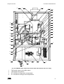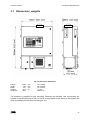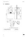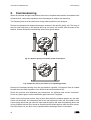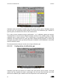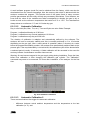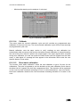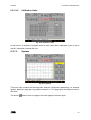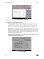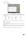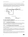
1
USER MANUAL CWD2005 PLUS UNION Instruments GmbH Combustion Calorimeter For high speed measurement of fuel gases Version: V1.01R05 Stand: 15.03.2010 User Manual CWD2005 Plus Union Instruments GmbH Zeppelinstrasse 42 76185 Karlsruhe Germany Phone Fax Email WWW 2 : +49 (0)721-95243-0 : +49 (0)721-95243-33 : [email protected] : http://www.union-instruments.com User Manual CWD2005 Plus 3 User Manual CWD2005 Plus 4 User Manual CWD2005 Plus Attention: Please read all safety instructions before using the CWD2005 PLUS See Chapter 1 5 User Manual CWD2005 Plus 6 User Manual CWD2005 Plus Contents Contents ................................................................................................................................. 7 1. Important Information.................................................................................................... 12 2. Introduction ................................................................................................................... 16 2.1 2.2 2.3 2.4 3. Analyzer Overview ........................................................................................................ 20 3.1 3.2 3.3 3.4 3.5 3.6 4. Output values ......................................................................................................... 16 Available measurement range ................................................................................ 17 Response time ........................................................................................................ 17 Specifications ......................................................................................................... 18 Dimensions, weights ............................................................................................... 25 Gas connections ..................................................................................................... 26 Gas consumption .................................................................................................... 26 Electrical power supply ........................................................................................... 27 Measurement range................................................................................................ 27 Ambient temperature limits ..................................................................................... 28 Installation .................................................................................................................... 30 4.1 4.2 4.3 4.4 4.5 Exhaust gas discharge............................................................................................ 32 Shelter requirement ................................................................................................ 32 Room ventilation ..................................................................................................... 32 Electrical power connection .................................................................................... 32 Gas connections ..................................................................................................... 33 4.5.1 4.5.2 4.5.3 4.5.4 4.6 5. 6. Process gas filters ......................................................................................... 33 Pressure regulators ....................................................................................... 34 Sample gas pump .......................................................................................... 36 Fast Loop connection .................................................................................... 36 Interfaces ................................................................................................................ 37 Commissioning ............................................................................................................. 38 Software ....................................................................................................................... 40 6.1 Screen layout.......................................................................................................... 40 6.1.1 6.1.2 6.1.3 6.1.4 6.1.5 6.1.6 6.1.7 6.1.8 6.1.9 6.1.10 6.1.11 6.1.12 6.1.13 6.2 Menu keypad ................................................................................................. 40 Trend display ................................................................................................. 41 Numeric display ............................................................................................. 41 Information field ............................................................................................. 41 Menu ............................................................................................................. 41 Start/Stop ...................................................................................................... 41 Numeric keypad............................................................................................. 41 Burner window ............................................................................................... 41 Status display ................................................................................................ 41 Arrow and data entry keypad ......................................................................... 42 Data input ...................................................................................................... 42 Keypad .......................................................................................................... 42 Menu navigation ............................................................................................ 42 Menu diagram......................................................................................................... 43 6.2.1 Options .......................................................................................................... 44 7 User Manual CWD2005 Plus 6.2.2 6.2.3 6.2.4 7. Maintenance ................................................................................................................. 72 7.1 7.2 7.3 7.4 7.5 8. Safety instructions for maintenance or repair .......................................................... 72 Periodic maintenance ............................................................................................. 72 Consumables.......................................................................................................... 72 Replacement of I/O boards ..................................................................................... 73 Spare parts packages ............................................................................................. 73 Troubleshooting ............................................................................................................ 74 8.1 8.2 8.3 8.4 8.5 9. Trend ............................................................................................................. 67 Event list ........................................................................................................ 70 Device info ..................................................................................................... 71 Event list ................................................................................................................. 74 Unstable reading..................................................................................................... 74 Drift in readings ...................................................................................................... 74 Incomplete ignition .................................................................................................. 74 Software troubleshooting ........................................................................................ 75 Measurement principle ................................................................................................. 76 9.1 9.2 Wobbe index measurement .................................................................................... 76 Specific gravity measuring cell ................................................................................ 78 9.2.1 9.2.2 9.2.3 9.2.4 9.2.5 9.2.6 9.2.7 Operational overview ..................................................................................... 78 Functional diagram ........................................................................................ 79 Output signals................................................................................................ 79 Initial operation .............................................................................................. 79 Testing and calibration................................................................................... 79 Maintenance .................................................................................................. 80 Technical specification................................................................................... 80 10. Circuit diagrams............................................................................................................ 82 10.1 Input-output card: EA internal ................................................................................. 82 10.2 Input-Output card E/A-Extern .................................................................................. 84 10.2.1 Input-Output card E/A extern Typ_06 ............................................................ 85 11. Appendix ...................................................................................................................... 92 11.1 11.2 11.3 11.4 11.5 Spare parts list ........................................................................................................ 92 Pressure regulators ................................................................................................ 92 Low sample pressure .............................................................................................. 92 Gas conditioning ..................................................................................................... 92 Gas connections ..................................................................................................... 93 11.5.1 11.5.2 11.5.3 Adjust pressure regulator ............................................................................... 93 Adjust pressure regulator ............................................................................... 93 Process gas connection ................................................................................. 94 11.6 Fast Loop ............................................................................................................... 95 11.7 Air consumption (Optional) ..................................................................................... 96 11.7.1 11.7.2 11.7.3 8 Calculated air consumption............................................................................ 96 Air consumption with CO measurement ......................................................... 96 Housing for outdoor installation ..................................................................... 98 User Manual CWD2005 Plus Figures Fig. 3-1 Front view................................................................................................................20 Fig. 3-2 CWD2005 Plus components shown above but without doors for clarity ...................21 Fig. 3-3 Rear inside view of main door .................................................................................23 Fig. 3-4 Enclosure shown from left hand side .......................................................................24 Fig. 3-5 Enclosure dimensions .............................................................................................25 Fig. 4-1 Enclosure attachment / Exhaust ..............................................................................30 Fig. 4-2 Mounting the analyzer .............................................................................................31 Fig. 4-3 Connector block assembly ......................................................................................33 Fig. 4-4 Small filter ...............................................................................................................34 Fig. 4-5 Filter with drain connection ......................................................................................34 Fig. 4-6 Fisher 912 pre-pressure regulator < 6 bars (90 PSI) ...............................................35 Fig. 4-7 High-pressure regulator GO PR1 < 250 bar (3600 PSI) ...........................................35 Fig. 4-8 High-pressure regulator GO PR1 < 250 bar (3600 PSI) ...........................................36 Fig. 4-9 Interface connection on the left-hand side of the main door .....................................37 Fig. 5-1 Specific gravity cell shown locked for transport........................................................38 Fig. 5-2 Specific gravity cell shown in its operating position ..................................................38 Fig. 6-1 Display screen and keypad......................................................................................40 Fig. 6-2 Menu diagram .........................................................................................................43 Fig. 6-3 Info field...................................................................................................................44 Fig. 6-5 Input/Output ............................................................................................................45 Fig. 6-4 Options ....................................................................................................................45 Fig. 6-6 Analog Output .........................................................................................................46 Fig. 6-7 Relay output ............................................................................................................46 Fig. 6-8 mA Display ..............................................................................................................47 Fig. 6-9 Digital inputs ............................................................................................................48 Fig. 6-10 Display ..................................................................................................................49 Fig. 6-11 Calibration menu, first layer ...................................................................................49 Fig. 6-12 Calibration menu, second layer .............................................................................50 Fig. 6-13 Configuration of calibration gas .............................................................................50 Fig. 6-14 Automatic calibration .............................................................................................51 Fig. 6-15 Automatic Calibration 2 .........................................................................................52 Fig. 6-16 Calibration limit ......................................................................................................53 Fig. 6-17 System ..................................................................................................................53 Fig. 6-18 System menu, second layer ..................................................................................54 Fig. 6-19 General settings ....................................................................................................54 Fig. 6-20 Ignition...................................................................................................................55 Fig. 6-21 Settings .................................................................................................................56 Fig. 6-22 Date and time ........................................................................................................56 Fig. 6-23 Language menu, first layer ....................................................................................57 Fig. 6-24 Language menu, second layer ..............................................................................57 Fig. 6-25 Language menu, third layer ...................................................................................58 Fig. 6-26 Change language ..................................................................................................58 Fig. 6-27 Change drive .........................................................................................................59 Fig. 6-28 Password ..............................................................................................................60 Fig. 6-29 Color settings ........................................................................................................60 Fig. 6-30 Hardware 1 ............................................................................................................61 Fig. 6-31 Database ...............................................................................................................62 Fig. 6-32 Service ..................................................................................................................63 Fig. 6-33 Configuration menu, first layer ...............................................................................64 Fig. 6-34 Configuration menu, second layer .........................................................................64 Fig. 6-35 Configuration menu, third layer ..............................................................................65 Fig. 6-36 Service mode ........................................................................................................65 9 User Manual CWD2005 Plus Fig. 6-37 Database configuration..........................................................................................66 Fig. 6-38 Status option in Database......................................................................................66 Fig. 6-39 Trend: Change time ...............................................................................................67 Fig. 6-40 Change time ..........................................................................................................68 Fig. 6-41 Change “y” values .................................................................................................68 Fig. 6-42 Change signals......................................................................................................69 Fig. 6-43 Change units .........................................................................................................69 Fig. 6-44 Move cursor ..........................................................................................................70 Fig. 6-45 Eventlist.................................................................................................................71 Fig. 6-46 Device info ............................................................................................................71 Fig. 9-1 CWD2005 Plus scheme ..........................................................................................76 Fig. 9-2 Functional diagram of the specific gravity measuring cell ........................................79 Fig. 9-3 Specific gravity measuring cell, heated and insulated ..............................................80 Fig. 10-1 Input/output card E/A internal showing module/plug positions. ..............................82 Fig. 10-2 Input-output E/A extern Typ_06 .............................................................................85 Fig. 11-1 Filter unit with bypass valve ...................................................................................93 Fig. 11-2 Calibration gas supply ...........................................................................................94 Fig. 11-3 Process Gas line (maximum pressure 60 bar) .......................................................95 Fig. 11-4 Process Gas line (maximum pressure 60 bar) .......................................................95 Fig. 11-5 Fast Loop ..............................................................................................................96 Fig. 11-6 CO Module installed in the CWD2005 Plus ...........................................................97 10 Important Information User Manual CWD2005 Plus 11 User Manual CWD2005 Plus 1. Important Information Important Information Thank you for choosing a Union CWD2005 Plus heating value analyzer for your online process measurement application. Please read this manual and follow all directions before installation and use of this analyzer. All shipping containers should be carefully checked for any included accessories. Check the shipment against the packing slip and any system arrangement drawings to ascertain that the shipment is complete. The analyzer was carefully inspected and calibrated at the factory. Check the shipment for possible damage incurred during transit. If there is any sign of visible damage to the crate or hidden damage inside the shipment, notify the carrier and the factory immediately as the equipment warranty does not cover damage in shipping. In the event of trouble during start-up, please contact a factory representative and inform them of the model and serial number of the unit, plus a fully description of the problem. Note: The factory will not be responsible if the customer attempts to repair the unit during the warranty period without first following any detailed factory instruction. All possible care has been taken in the publication of this user manual but Union Instruments, its agents and distributors, accept no liability for any inaccuracies or omissions that may be found. This manual reflects the state of the product at the issue date below but further refinements may mean that the manual does not fully reflect your particular system. Union Instruments reserves the right to make change without notice both to this publication and the product that it describes. Before start up and use of the CWD2005 Plus, please take time to carefully review this manual and its contents. Observe all Warnings, Cautions and Notes. Initial operation: All electrical connections to line power must be carried out by qualified, responsible technical personnel. The internal electrical components of the analyzer are wired in accordance with NEC, VDE and International standards. Check the power supply voltage, details can be found on the technical data label inside the door. The gas connections should be installed by authorized personnel only. All instructions for the in-situ installation have to be considered. Warning: During installation of the protective conductor connection please consider the existing rule for instruments with higher leakage current (> 3.5 mA). The CWD2005 Plus operates over a specified ambient temperature range. Directly exposing the analyzer to temperature outside the range is not recommended. There may be damage occurred due to adverse weather conditions if an outdoor shelter is not used. 12 Important Information User Manual CWD2005 Plus One has to be careful working with pressurized flammable gases that will be connected to the analyzer. The Installation procedure must conform to all applicable local and national codes. All process gas lines have been actually leak-tested at 1.5 times the normal operating pressure during assembly at the factory. After installation, the entire process gas system should be pressurized and tested for leaks before operation. When planning the installation, local site conditions must be taken into account. The analyzer has a small open flame inside. Any hazardous area regulations for applicability should be considered. There may be requirement of an air purge system to the analyzer‟s shelter in order to conform hazardous area regulations. The air purge system will ensure the LEL inside the enclosure remains well within the allowable limits of a standard defined by local or national authority. Note: A purge system can also be useful for application in very dusty areas. A small source of air for combustion is necessary. Generally we must ensure that flue gas is not allowed to accumulate inside the shelter (CO, H2 and H2S may be present) and that any combustion heat is discharged so that the analyzer‟s thermal stability remains unchanged. Any outside vent needs protection from wind to avoid back flow of flue gases into the unit and the possibility of unstable readings. The analyzer is equipped with numerous safety features and the ignition can only occur when the door closed. In the event of failure of gas or cooling air supply, the inlet gas solenoid valve will automatically be closed and after a short time interval the valve will reopen and the analyzer will be back in ignition cycle. If the ignition cycle or online measurement function is aborted due to flame out or power failure, the gas supply valve reverts to its normally closed position and process gas flow is instantly terminated. User intervention is then necessary to resolve the problems source. Calibration is only possible if a calibration gas cylinder is available and contains the correct certified gas. The mixture will normally be similar to the major process gas components with a value around 80% of the analyzer‟s range. CWD2005 Plus gas consumption is between 8 and 200 liters per hour and the quantity will depend on the characteristics of the process gas. The use of a gas flow restrictor in designing an outdoor shelter for the analyzer is recommended since it will limit the „potential to release‟ in case of any accidental damage of process gas tubing inside. Maintenance: Maintenance of the unit is only done after disconnecting the main switch. The following points have to be considered before maintaining or repairing the electrical or the high voltage equipment. After switching off the main switch the capacities of the equipment store up to 5 min high voltage. It is important to wait till the voltage brake down to zero. Please pay attention to the safety function of the current circuit breaker. It is forbidden to manipulate the safety switch in the main door. 13 User Manual CWD2005 Plus Important Information Parts of the burner could be very hot during operation (more than 200 °C). Before doing any service at the burner please wait about 15 min to cool down all burner parts. During start-up or maintenance as well as in not optimal conditions (not 100 % gas burned) there could be a danger of gas components in the exhaust of the system. If process gas has toxic components please consider that all actual safety rules have to be fulfilled. In case of using non-toxic gases there will be no problems since they are highly diluted with cooling air. 14 Important Information User Manual CWD2005 Plus 15 User Manual CWD2005 Plus 2. Introduction Introduction Combustion calorimeter has been an important part of industrial process control scene in last few years. Some units are valued for their low maintenance requirement, rugged durability and simple to be understood and serviced quickly by anyone without needing any special tools. Principally in combustion calorimeters, a small amount of process gas is burned and then cooled by a controlled fluid (usually air). The temperature of the burned gas is measured and it corresponds to the heat release. The goal of a few manufactures has been to improve response speed of these online units. Over the years, technical progress and the embodiment of smart design strategies have improved response times from around 5 minutes for the old mechanical water bath based units down to just a few seconds for the newly introduced CWD2005 series. The CWD2005 Plus is the successor to the CWD 2005, CWD 2000, CW95, CW85, CW71 and all previous models (about 10,000 units supplied) during more than 85 years service to the gas industry. Compare to CWD2005, the CWD2005 Plus has stability and accuracy over temperature disturbance or fluctuation of the ambient temperature. It has also a database system that later can be transferred to USB mass storage and also some other new features. The CWD2005 Plus is a high-speed combustion calorimeter with a small industrial PC and large digital display, mounted with the combustion chamber, thermopile and other vital components in a custom wall mounted enclosure. A small amount of process gas is measured continuously and the temperature rise from heat of combustion is transferred from the burner to the thermopile, via the cooling air supply and is measured by its thermopile sensor as heat rise. Measurement is based on the real time wobbe index and specific gravity values of the gas (a specific gravity sensor is built into the calorimeter). The PC-based microprocessor calculates calorific value using the following formula: Calorific value WobbeIndex Specific Gravity The CWD2005 Plus is a high-speed combustion calorimeter and is usually preferred in control applications since it has fast time response, direct measurement and simple to maintain online by gas, industrial, steel and petrochemical companies. It measures the calorific value of the process gas and simultaneous outputs are available for both upper and lower calorific values as well as wobbe index and specific gravity. Petrochemical industries often need to measure flare gases with many unknown gas components and need to meet the uptime requirements of tough environmental regulations. The CWD2005 Plus combustion calorimeter responds to all unknown components in the process gas and reports them as heating value or wobbe index. 2.1 Output values The connection board PCB provides a series of removable terminal strips where the 0-20 or 4-20 mA DC isolated outputs (proportional to the measuring range) and eight user programmable alarm contacts are available for customer connection. 16 Introduction User Manual CWD2005 Plus The combustion calorimeter has system to compensate changes of the ambient temperature. During selection of a suitable location please avoid dusty areas, locations with strong drafts, rapid temperature changes, direct sunlight or other sources of thermal radiation. TRE - 7°C < TR < TRE + 7°C where TR room temperature TRE room temperature during calibration dTR dt 2C hour 2.2 Available measurement range Normally 40 - 100 % of the full-scale range can be used depending on the gas composition. Gas specification: Gas Family Wobbe index 3 range (kWh/m ) Nominal 3 (kWh/m ) Group H 12,8 to 15,7 15,0 Gas Natural gas “H“ Natural gas “H“ + LPG + Air Max. specific gravity 0,75 Max. olefin components 10 weight.-% Bio-methane 98-100 vol.-% CH4 0-5 vol.-% CO2 Natural gas H + bio-methane + LPG Group L 10,5 to 13,0 12,4 Natural gas “L“ Natural gas “L“ + LPG + Air Max. specific gravity 0,75 Max. olefin components 10 weight.-% Natural gas “L“ + bio-methane + air Max. 15 vol.-% air (max. 3 vol.-% O2 in dry gas line, max. 0,5 vol.-% O2 in humid gas line) 2.3 Response time Deadtime 50%-time 90%-time 99%-time 3 sec 7 sec 20 sec 45 sec Response times are measured when the gas reaches the burner. The values shown above were measured using methane. Gases with other specific gravities and rate of flame propagation generate different response times, some faster and some slower, depending on the properties of the gas. Gas consumption varies due to difference of specific gravity and flaming temperature. 17 User Manual CWD2005 Plus Introduction In addition to the dead time and response time, the sample lag time during flow of process gas through the supply tube and fittings in the unit must be added. The gas consumption is based on the total sample volume up to the burner. In page 24, two formulas show how to calculate the total response time. A fast loop is recommended on long sample lines, see section 4.5.4. 2.4 Specifications Measured Variables Measurement range 8,4 –13,1 kWh/m³ 30,2 – 47,2 MJ/m³ Accuracy (Hs or Wobbe) ± 1% measurement value Accuracy specific gravity ± 0,5% full scale Linearity ± 0,2% Reproducibility ± 0,1% 0-point stability ±0,2% per month Interfaces RS232 (9600 Baud, 8 Data bit, 1 Stop bit), Profibus-DP-DP (Anybus Communicator) Analog outputs 4 - 20mA for Hs, Hi, wobbe and density Digital outputs 8 Relays and 4 open-collectors Digital inputs Start Measurement, Start Calibration, Hold Signal, Calibration Abort Process gas (dry gas (xH20 ≤ 1 g/kg)) Gases according DVGW-Worksheet G260 Biogas according DVGW- Worksheet G262 Natural gas Gas connection prepressure 15 - 18 mbar Gas consumption 15 - 20 l/h (min. spec. gravity 0,55 with wobbe-jet 0,55mm) Air requirement ca. 30 m³ per hour (Air in the installation room with max. 50 ppm of flammable components) Calibration gas Methane, max. 0,05% Impurity (pureness ≥ 3,5) Calibration interval Minimum once a day Calibration gas consumption ca. 2-5 Liter per calibration (10-20 Minutes pro calibration) Ambient conditions 18 Higher heating value, Hs; Lower heating value (Hi); wobbe index, specific gravity, air requirement Installation room required Temperature condition Room temperature between 5 °C and 35 °C Temperature fluctuation ≥ 5 °C per hour Electrical supply 220 Volt / 110 Volt, 50 / 60 Hz AC Dimensions 50 x 1020 x 320 mm, ca.74,5 kg Introduction User Manual CWD2005 Plus 19 User Manual CWD2005 Plus 3. Analyzer Overview Analyzer Overview All major components are shown below and can be replaced if necessary as a spare part. Items marked with an * are not visible on this drawing – see following drawings. 9 8 10 8 8 11 8 11 1 2 3 4 5 6 7 Fig. 3-1 Front view 1 3 5 7 9 11 20 Signals cable gland Signals cable gland M16 ground cable gland Switch on … off Flue gas outlet Analog signals covering 2 4 6 8 10 Signals cable gland M20 power supply cable gland Filter covering Door lock Display Analyzer Overview User Manual CWD2005 Plus 38 1 37 2 3 4 5 6 7 36 8 35 9 34 10 11 33 12 32 13 31 14 30 29 15 28 27 26 25 24 20 21 18 17 16 19 22 23 Fig. 3-2 CWD2005 Plus components shown above but without doors for clarity 1 2 3 4 Thermopile output (mV wobbe index) Thermopile fixing screws PT 100 Sensor temperature compensator PT 100 Sensor cooling air inlet temperature 21 User Manual CWD2005 Plus 5 6 7 8 9 10 11 12 13 14 15 16 17 18 19 20 21 22 23 24 25 26 27 28 29 30 31 32 33 34 35 36 37 38 22 Burner enclosure Burner Cooling air orifice measurement “-“ Cooling air orifice measurement “+” Ignition electrode Measuring orifice Enclosure purging Ignition transformer Ignition transformer line filter Air fan Power supply for air fan Power supply line filter for air fan Power supply terminal block Signals cable gland Signals cable gland Signals cable gland Signals cable gland Line power cable gland Signals cable gland Extern electronic - output/input signal digital and analog Ignition transformer safety switch Burner window Intern electronic – analog/digital-converter, solenoid valve control Differential pressure sensor for wobbe jet Cap for wobbe jet Precision pressure regulator Gas pressure sensor Wobbe jet differential pressure for specific gravity cell Gas pre-pressure regulator Specific gravity cell Process gas solenoid valve Calibration gas solenoid valve Flue gas outlet pipe Breather pipe Analyzer Overview Analyzer Overview User Manual CWD2005 Plus Fig. 3-3 Rear inside view of main door 1 3 5 7 Power supply Power supply fan ETX Board Backside Keypad 2 4 6 Port for connections Mainboard Blower ETX Board 23 User Manual CWD2005 Plus Analyzer Overview Fig. 3-4 Enclosure shown from left hand side 1 3 5 7 9 11 M20 Cable gland, signals M20 Cable gland, signals M20 Cable gland, signals Interface connections Carrier gas (SV. X11/3-4)* Calibration gas (SV. X14/1-2) 2 4 6 8 10 12 M25 Cable gland, power M16 M20 Cable gland, signals USB port Fast loop* Calibration gas 2 (SV. X14/3-4)* Process gas (SV. X11/1-2) The above drawing shows a standard analyzer or analyzers equipped with one or two calibration gases or carrier gas. Analyzers with the option of two process gases have a different inlet arrangement and this will be labeled on the analyzer. The items marked with a “*” are available as an option at the time of order and are not supplied as standard. 24 Analyzer Overview User Manual CWD2005 Plus 3.1 Dimensions, weights Fig. 3-5 Enclosure dimensions Height: Width: Depth: Weight: Protection: 1020 720 337 50.5 IP44 mm mm mm kg 40.2 inches 28.3 inches 13.3 inches 111 lbs NEMA 12 The analyzer is supplied for wall mounting. Brackets are included. Gas connections are located on the left-hand side of the unit. Allow enough space for the doors to swing open and other accessibility issues when mounting the unit. 25 User Manual CWD2005 Plus Analyzer Overview 3.2 Gas connections Gyrolok ¼” tube (6 mm) gas connections are located on the left hand side of the unit. Process and calibration gases should be connected separately. If a very short response time is required, a tube with a smaller diameter 1/8” (4 mm) can also be used. Check that the pressure drop is not too large for every gas that we use. Input pressure to the analyzer must be between 20 and 40 mbar (12” H2O). Lower calorific gases (1000 kcal) require a pre-pressure of 40 to 60 mbar (24” H2O). If input pressure is too low, then it should be boosted with a process gas pump. A pump is available as an option, and can be mounted on a panel with the necessary pressure gauges and pre-pressure regulator. A filter is needed in the process gas line and can be ordered as an option from the factory or supplier. A small filter will be sufficient when natural gas is used since this gas is normally clean. Larger filters are necessary for dirty gases such as blast-furnace gas and coke oven gas. The volume of the filter will affect the response time and the filter element should have a large active face retention area and a small dead volume. If a process gas with high humidity is at a much higher temperature than ambient, temperature decreasing in the process gas line due to low ambient temperature can produce condensation of water and this must be avoided. The gas has to be dried or a water separator with a drip leg installed at the lowest point of the process gas line. The gas rapidly warms up above ambient inside the analyzer so there is no danger of condensation. 3.3 Gas consumption Gas consumption will depend on the range orifice (wobbe jet) in the analyzer, and the specific gravity of the process gas. Natural gases require 15-20 liters of gas per hour. Blast furnace gases with low calorific values require up to 200 liters per hour. Use the following formula to calculate the gas consumption based on specific gravity and range orifice (wobbe jet) diameter. Quantities expressed in l/h or scf/h. Gas consumption 48d 2 liter D hour or Gas consumption Wobbe jet diameter (d) Specific gravity 26 1.695d 2 scf 3 hour D : in mm : process gas/calibration gas Analyzer Overview User Manual CWD2005 Plus Example 1: Wobbe jet Size: S.G. Natural gas: 0.55 0.642 The Natural gas consumption corresponds to a range of Wobbe Index of: 14000 Wobbe (kcal/Nm³) or 60000 Wobbe (kj/Nm³) 18.1 liter/h In BTU and cubic feet 0 – 1450 Wobbe (Btu/ft.³) 0.64 ft³/hour. Example 2: Wobbe jet Size: S.G. Coke gas: 0.85 0.422 The Coke gas consumption corresponds to a range of Wobbe Index of: 6000 Wobbe (kcal/Nm³) or 25000 Wobbe (to kj/Nm³) 53.22 liter/h In BTU and cubic feet 0 – 630 Wobbe (Btu/ft.³) 1.89 ft³/hour. Example 3: Wobbe jet size: S.G Blast Furnace gas: 1.85 1.032 The Blast Furnace gas/Coke gas consumption corresponds to a range of wobbe Index of: 1400 Wobbe (kcal/Nm³) or 6000 Wobbe (kj/Nm³) 152.5 liter/hour In BTU and cubic feet 0 – 150 Wobbe (Btu/ft.³) 5.41 ft³/hour. 3.4 Electrical power supply CWD2005 Plus power consumption is as follows 230 Volt 50/60 Hz 250 VA 115 (110) Volt 50/60 Hz 250 VA The analyzer is supplied for operation at 230 or 115 Volts. Conversion to another voltage by the user requires the following items to convert from 230 to 115 Volts: The ignition transformer and a switching relay must be exchanged for more suitable voltage. 3.5 Measurement range Measurement range: 8,4 –13,1 kWh/m³ or 30,2 – 47,2 MJ/m³. 27 User Manual CWD2005 Plus Analyzer Overview 3.6 Ambient temperature limits The CWD2005 Plus should be installed in a room that does not exceed minimum and maximum temperature requirements. A typical temperature range is 10°C to 38°C (50 °F to 100°F). Higher (100°F or more) or lower temperatures will require cooling or heating. Maximum and minimum ambient temperatures must be specified, so that the installation location can be modified if required. Slow temperature fluctuations are fully compensated by the analyzer. Very rapid temperature fluctuations should be avoided since the compensation is always reactive, not pro-active. The analyzer is able to compensate for rapid fluctuations after a specific time (2 to 3 minutes) and steady state conditions return. An outdoor shelter with climate control can also be supplied as an optional extra. The CWD2005 Plus can be equipped with an optional onboard temperature controller for better temperature control of the whole system (environmental temperature – shelter temperature). Heating and/or cooling can be provided depending on the ambient conditions. Cooling is always possible with compressed air, air conditioning unit or even water. 28 Analyzer Overview User Manual CWD2005 Plus 29 User Manual CWD2005 Plus 4. Installation Installation 4 3 2 1 Fig. 4-1 Enclosure attachment / Exhaust 1 3 30 discharge CWD2005 Plus flexible aluminum duct hose 2 4 hose clamp fastening strip Installation User Manual CWD2005 Plus The analyzer is intended to be mounted on the wall. 2 special fastening strips supplied from the manufacturer. They are equipped with 8 mm pins attached to the wall. On the back of the analyzer, there are holes in the struts affixed according to figure. A distance of 840mm must be available between the mounting strips (see Figure 4-2) to meet exactly the holes vertical distance on the back of the analyzer. Fig. 4-2 Mounting the analyzer The unit can also be installed on a freestanding rack and a stainless steel support bracket is available, which must be ordered separately. 31 User Manual CWD2005 Plus Installation 4.1 Exhaust gas discharge The small quantity of flue gas is mixed with 25 m³ of air after combustion and is heavily diluted with an exhaust temperature around 8-20 °C (15°F) above ambient. Flue gas must be discharged from a flue gas outlet to ensure that the thermal balance is not disrupted. This is particularly important with small enclosure or shelter, as air inside may become oxygendeficient and stale if the supply of combustion air is too small. The very small quantity of sample gas is equal to several pilot lights of domestic stove and poses no health hazard for most process gases such as natural gas etc. It is an advantage to generate a slightly higher pressure in the shelter (ventilator or fan) so that all flue gases are discharged from the outlet. This is particularly a case for corrosive gases. Corrosive air in the calorimeter enclosure will result in corrosion of the electronic components. In some other cases, it is advantageous for an enclosure or shelter to be purged with clean dry air. All parts of exhaust system are included with the analyzer. 4.2 Shelter requirement The calorimeter shelter is subject to special conditions. The quality of measurement extremely depends on how well these conditions are met. Room temperature changes must be slow. If necessary, only well controlled air conditioning systems should be used. If an electrical heater is used, the controller should be programmed very carefully. Maximum ambient temperature should not be more as 40 °C. A higher temperature will not damage the analyzer. It will affect only the accuracy of the measurement. Direct sunlight from a window should be avoided, since the additional radiant heat will disturb the energy balance in the room. 4.3 Room ventilation CWD2005 Plus calorimeter requires approximately 30 m³/h of air. This air must be delivered from outside the enclosure using suitable ventilation. The fresh air should not be connected directly into the analyzer but should enter the room via a heater or a roundabout route, so that the temperature of the air has time to adjust to the internal enclosure air temperature. With some careful design and attention to a few simple points the possibility for thermal shock can be greatly reduced or eliminated completely. Note: Sections 4.1, 4.2 and 4.3 are for customer guidance if a shelter has not been purchased from the factory as part of the original order. 4.4 Electrical power connection The electrical power supply connections are wired to the terminal block in the bottom section of the enclosure; see Fig. 3-2 and Fig. 4-3. Check whether the available voltage supply matches the analyzer‟s requirement voltage. 32 Installation User Manual CWD2005 Plus Fig. 4-3 Connector block assembly 1 3 5 7 9 Power supply line Door safety switch Power supply for electronic Door switch signal Fan with power supply 2 4 6 8 Analyzer main switch on/off Line filter Ignition transformer Ignition impulse input 4.5 Gas connections Gas connections should be leak-tested before use. Different type of Gyrolok should be used depending on the type of the process gas. Up to 5 inlet connections are possible if all options including process gas, two calibration gases, carrier gas and fast loop are specified. 4.5.1 Process gas filters Two types of gas filters are recommended. Natural gas and other relatively clean gases need a filter with small internal volume. Filter elements need to be changed occasionally and a pressure gauge can be used to check filter “back pressure”. The mA hold function can be activated before changing the filter to provide a continuous output signal during filter maintenance. Be sure to cancel memory hold after use. It is possible to order filter with a bypass. 33 User Manual CWD2005 Plus Installation Fig. 4-4 Small filter 1 3 5 Inlet 6 mm Gyrolok Removable element tap Filter 20-30 2 4 Outlet 6 mm Gyrolok Filter housing SS 316 Dirty gases need a filter with a larger volume and this will increase dead time. Fig. 4-5 Filter with drain connection 1 3 5 7 Filter inlet Inlet 6 mm Gyrolok Filter 99,8% at 0,1 Filter housing SS 316nn 23 cm³ (1,4 ft³) 2 4 6 Filter way Outlet 6 mm Gyrolok Filter cap 4.5.2 Pressure regulators Good pressure regulation is very important for measurement stability. Four different pressure regulators for different applications (and markets) are recommended as options and short description is provided for each regulator in the following section. The outlet pressures range between 20 mbar and 55 mbar (10”-24” H2O) depending on type. Gas pressure higher than 6 bars (90 PSI) needs a primary regulator to reduce the pressure to the inlet of the pre-pressure regulator. The standard analyzer consists of one process gas inlet and one calibration gas inlet and both inlet ports require a pre-pressure regulator. All connectors are mm or inch. Adjust the process gas and calibration gas regulator outlet pressures to read the same pressure when gases are switched, this is important for measurement stability. The first pre-pressure regulator < 6 bar (90 PSI) has a die-cast-zinc housing and internal parts are made of steel and die-cast-zinc. 34 Installation User Manual CWD2005 Plus Two control springs are available: 12 - 25 mbar (10” H2O) orange and 30 mbar (20” H2O) blue. Fig. 4-6 Fisher 912 pre-pressure regulator < 6 bars (90 PSI) 1 3 Inlet 6 mm Gyrolok Control spring 2 4 Outlet 6 mm Gyrolok Ventilation valve The next unit is a primary regulator < 250 bars (3600 PSI) type GO PR1 has a 316 SS housing and gauges. The outlet (2) pressure is adjustable from 0–3.4 bar. A pre- pressure regulator is still necessary and acts as a second stage inlet pressure control for the CWD2005 Plus. Fig. 4-7 High-pressure regulator GO PR1 < 250 bar (3600 PSI) 35 User Manual CWD2005 Plus 1 3 5 Installation Inlet 6 mm Gyrolok High pressure gauge Pressure control wheel 2 4 Outlet 6 mm Gyrolok Low pressure gauge The last is a primary regulator < 250 bar (3600 PSI) with a 316 SS body and gauges adjustable outlet pressure from 0 – 3.4 bar and has a gas cylinder CGA connection. Hydrocarbons W 21.8 x ¼“ left. DIN 477 Nr.1 or CGA sized fittings. Mixed gas M19 x 1.5 LH DIN 477 Nr.14 or CGA sized fittings. A pre-pressure regulator is still required after the high-pressure calibration gas cylinder regulator, for two-stage inlet pressure control. See Fig. 11-2 Chapter 11.5.1. Fig. 4-8 High-pressure regulator GO PR1 < 250 bar (3600 PSI) 1 3 5 Inlet connection to gas cylinder High pressure gauge Pressure control wheel 2 4 Outlet 6 mm Gyrolok Low pressure gauge 4.5.3 Sample gas pump If the process gas inlet pressure is lower than recommended then a process gas pump should be installed to boost the sample gas pressure. Gas at higher pressure can then be regulated, so that the recommended gas pressure is maintained at the sample gas inlet. The pump must meet the requirements for flow and installation area classification. See Chapter 11 for more details. 4.5.4 Fast Loop connection For a more rapid response time, a fast loop connection can be provided. A T-piece with a pressure regulator and a flow meter is inserted before the calorimeter and the excess gas sample is piped to a lower pressure location or a vent header. The dead time can generally be reduced by a factor 1:5 and this normally depends on the gas type and the pressure ratios in the sample tubing. See section 11.6 for more details. 36 Installation User Manual CWD2005 Plus 4.6 Interfaces Many of necessary electronic devices can be connected to the CWD2005 Plus. The analyzer can be operated using a plug in mouse and a standard PC keyboard with PS2 connector. It has also USB port for transfer database and graphic. Fig. 4-9 Interface connection on the left-hand side of the main door 1 3 5 USB port Mouse port Parallel port 2 4 VGA Display Keyboard port 37 User Manual CWD2005 Plus 5. Commissioning Commissioning When all electrical and gas connections have been completed and tested in accordance with all instructions, codes and regulations then the analyzer is ready to be started up. The following work must be carried out during initial operation of the analyzer: Remove the transport tie wraps and transport screws on the specific gravity cell. The body of the cell must hang free on the springs and may not come into contact with the sides of the bracket. Screws should be removed and stored, see figures below. Fig. 5-1 Specific gravity cell shown locked for transport Fig. 5-2 Specific gravity cell shown in its operating position Remove the transport packing from the gas pressure regulator. Polystyrene foam is located beneath the removable regulator cover and must be removed before use. Check the process and calibration gas connections for tightness and correct connection. Check any carrier gas or second calibration gas connection if supplied. Switch on the main power switch. After a short delay while the analyzer powers up, the main screen will illuminate. An information field in the top right hand corner will show status. After a short purge period the gas valve will open and the ignition will start automatically (Note: this is only possible with the door closed as a safety switch inhibits ignition while the door opens). Once the flame is lit, the door can be opened without creating a flame out condition. 38 Commissioning User Manual CWD2005 Plus The device will start up and after short warm-up period (20-30 minutes during first initial operation from cold) will reach the correct process gas calorific value. CWD2005 Plus software, measuring ranges and any other specified options have been preconfigured at the factory (see datasheet and memory stick supplied with the unit). Following start-up, the gas pressure indication on the screen will read 4 mbar, and the cooling air differential pressure gauge (blue) will also show 4 mbar. If the gas pressure needs adjustment add or subtract weights from the precision weight loaded regulator. The air pressure should need no adjustment by the user since it is controlled by variable speed of air fan. Check the specific gravity differential pressure indication on the screen reads 4 mbar and adjust if necessary, see section 9.2.4 for more details. After the warm-up period, the analyzer will show the calorific value, wobbe index and specific gravity, numerically in the display and a visual trend will be developed onscreen. The menu system is described in Chapter 6, and this describes how the user enters their application specific values into the various menus. Be sure to read this chapter to gain some familiarity with the equipment before any ad-hoc experimentation or adjustment to the menus. If the analyzer should fail to power-up, open the main door and check inside the door that the power supply ribbon cable connections are firmly attached to the power supply as sometimes these have detached during rough shipment and handling. If questions arise during start-up contact the factory with serial number for further advice. The analyzer is supplied factory calibrated and field calibration should only be attempted by users, with a source of calibration gas with known values. Check the calibration gas data (see section 6.2.1.2) and enter the values in the correct menu. If only the gas component percentage is known, the correct wobbe index value must be calculated from the individual components. The use of cylinders with vendor supplied certified values for BTU and specific gravity is recommended as the accuracy of the calibration depends on the accuracy of the standard calibration gas used for calibration. 39 User Manual CWD2005 Plus 6. Software Software Attention: this manual is based on software release version V 1.02. The CWD2005 Plus runs on a real time operating system. It consists of a number of menu levels, which can be accessed using the keypad (soft keys). All operations are similar and are entered via a series of interactive menus with user dialog boxes, system prompts and activity messages. An on-screen mimic along the bottom edge of the display adapts to the changing requirements of all the corresponding menus and redefines keypad function. Please see Fig. 6-1. The menu buttons (1) always leads to the next higher menu level. The menu button (5) always returns the user to the start menu regardless of menu level. When addressing the software interface please allow one second between keypad 6.1 Screen layout Fig. 6-1 Display screen and keypad 1 2 3 4 5 Menu keypad Trend display Numeric display Info field Return to main menu 6 7 8 9 10 Start/Stop Numeric input keypad Burner window Status display LED Arrow and data entry keypad 6.1.1 Menu keypad The menu keypad is described in the software section and the function depends on the menu currently displayed and the function changes from menu to menu. 40 Software User Manual CWD2005 Plus 6.1.2 Trend display The trend display shows the both the trend and the interactive screens of the other menus. An area is also dedicated to the display of current measurement variables. 6.1.3 Numeric display The numeric display shows the measured values and units of measurement. 6.1.4 Information field The info field provides a lot of information: Time, operating mode, software version, methane percentage and other variables depending on the menu displayed. Additional information is available depending on the specific menu section. The lower section of the info field is reserved for internal information. The first line is the mV signal from the thermopile. V is the signal in Volts from the specific gravity cell. T1 is the air temperature in °C at the thermopile entrance and the next value is the differential temperature of any change in incoming air temperature. The variable p is the differential air pressure. Fr is the current frequency of the fan speed controller and this value is helpful to monitor the condition of the air filter. Stab. = signal stability value. During calibration the CWD2005 Plus determines the calibration duration based on current stability versus a preset stability value of < 0.15 to complete the calibration cycle and this level ensures that a stable calibration endpoint is reached. Info field is an important source of information when logging troubleshooting data. 6.1.5 Menu The menu key leads the menu display back to main menu regardless of menu or level 6.1.6 Start/Stop This key shuts stop the system without switching the main power switch off. The air blower can also be programmed for a delayed shutdown or keep running. This option can be activated in menu 6.2.1.3.1. The key also stores the data in the system memory. Note: A system storing is performed every 15 minutes. 6.1.7 Numeric keypad For data input (the “comma” key is the decimal point) and escape from a menu. 6.1.8 Burner window One can observe the burning flame through the burner window. The burner provides heat to the thermocouples of the thermopile. The flame status shows as a red LED, steady = flame ok, flashing = flame out. The system needs a stable symmetric blue flame for a stable measurement. 6.1.9 Status display There are 4 LEDs showing the following statuses: Power: Light for power on. Operation: In normal operation the LED flashes. 41 User Manual CWD2005 Plus Software Service: Indicates the need to change the filter element. The upper or the lower limit of the frequency controller has been reached. Disturbance: Indicates a fault alarm condition. 6.1.10 Arrow and data entry keypad The arrow key moves the cursor in the different menu screens. The enter key confirms the given value. 6.1.11 Data input Some of dialog boxes have “value” fields (where one can enter numerical number) and “list” (where one can choose from the list) fields. 6.1.11.1 Value fields The numerical values can be given by numeric keypad. Using the arrow keys, you can move on to the next numerical field. Use the escape option to abort changes. 6.1.11.2 List fields The list of text based field content can be selected by the user with the menu keys <back><next>. Confirm the entry of a new item using Enter or the Arrow Keys, which lead to the next menu and text field. 6.1.12 Keypad The keypad operator matrix is polled by the microprocessor once per second and pressing the button faster than one second will receive no system response. 6.1.13 Menu navigation The block diagram shows three different shaped menu areas. The simple square areas indicate that there are more menu levels. The rectangle with the rounded corner indicates that menu is at the lowest menu level. The double square indicates the location of an interactive input screen for value or data fields. 42 Software User Manual CWD2005 Plus 6.2 Menu diagram 6.2.1.3.7.2.1 Change language 6.2 6.2.2 Main 6.2.1.1 6.2.1.3.7.2.2 I/O Bit maps on/off Trend 6.2.1 Choices Options 6.2.2 6.2.2.1 Trend Change time 6.2.3 6.2.2.2 Eventlist Change “y“ values 6.2.1.1.1 6.2.1.3.7.2.3 Analog Output Transfer D:-> C 6.2.1.3.7.2.4 6.2.1.1.2 Relay Output 6.2.1.3.7.2.5 6.2.1.1.3 Disp. mA 6.2.2.3 6.2.4 Change signals Device info Store PCX files Digital Input 6.2.1.3.7.2.7 6.2.1.1.5 Display 6.2.2.5 6.2.1.3.7.2.9 6.2.1.2 I/O New dictionary Calibration 6.2.1.2 Calibration 6.2.1.3.7.2.8 PCX Info Move cursor 6.2.1.1 6.2.1.3.7.2.6 Delete PCX files Change units Options Read PCX files 6.2.1.1.4 6.2.2.4 6.2.1 Transfer C: -> D 6.2.1.3.7.2.10 6.2.1.3 6.2.1.3.1 System General 6.2.1.2.1 Config. calibr. gas Change drive 6.2.1.3 System 6.2.1.3.2 Ignition 6.2.1.2.2 6.2.1.3.7.1 Automatic calibr. Date/Time 6.2.1.2.3 6.2.1.3.7.2 Automatic calibr. 2 Language 6.2.1.4 Service 6.2.1.3.3 Export CSVfile 6.2.1.2.4 6.2.1.3.4 Hold signal on/off 6.2.1.3.5 Calibrate 6.2.1.3.7.3 Password 6.2.1.2.5 Store basic calibration 6.2.1.3.7.4 Color Settings Settings 6.2.1.2.6 6.2.1.3.6 Database Calib. limits 6.2.1.3.7.5 Hardware 1 Fig. 6-2 Menu diagram 43 User Manual CWD2005 Plus Software The info field is in the top-right corner. It shows actual information. Additionally actual measuring data are indicated according to the actual menu. Different information is available in every individual screen. All of these will be described in the manual. Fig. 6-3 Info field V 1.02 is the version number of the CWD2005 Plus software. The analyzer runs on process gas. During calibration it switches to calibration. Actual date and time. Methane volume percentage is 109.93% 23.89 mV is the signal from the thermopile 1.107 Volt is the signal from specific gravity cell T1=33.72/18.40 input air temperature in the thermopile in relation to heated air, with temperature difference 18.40 °C. 4.00 (mbar) air difference pressure. Fr = 66.38 controlled frequency of the fan. Stab = 11.870 is the stability, defines as standard deviation of the measured value average over 2 min. This information is important for a successful calibration. A typical value at the end of calibration is less than 0.015. Under this value calibration is finished. 6.2.1 Options The Options menu contains all of the following menus: Button menu. 44 leads back to the main Software User Manual CWD2005 Plus Fig. 6-4 Options The free area of the info field is reserved for important information. This information belongs to the actual menu level. For example, communication error indicates that the connected printer cannot communicate with the system. Filter change or over temperature are the common information. 6.2.1.1 I/O (Input/Output) Fig. 6-5 Input/Output Input and output can be linked together in any order. In the software, multiple identical outputs for a single measured value can also be programmed. For example: 3 outputs for wobbe index or 2 outputs for specific gravity etc. 3 remote contact inputs and 4 numeric screen displays are provided. 6.2.1.1.1 Analog output The symbols and back to the main menu. move the highlighted value left or right. The symbol leads 45 User Manual CWD2005 Plus Software Fig. 6-6 Analog Output The following items listed below can be selected from a series of the lists. Users can define the allocation order of the analog outputs and other data. Example: wobbe = number 1 or 2 or 3 etc. Cal. V. = number 3 or 2 or 1 etc. Signal is a multiple choice scrolling list field with the following text entries: Calorific value; wobbe, < wobbe >, specific gravity, CV net <or gross>. Type is a list field with the following entries: 0 – 20 mA or 4 – 20 mA ”Unit” is a list field with the following contents: Calorific: BTU /ft3, kJ/m3, MJ/m3, kWh/m3, kcal/m3, kJ/Sm3, MJ/Sm3, kWh/Sm3, kcal/Sm3 Specific gravity: specific to air (1.0), absolute kg/m3 “Range from” – “Range to” are value fields for numerical inputs. 6.2.1.1.2 Relay output Fig. 6-7 Relay output 46 Software User Manual CWD2005 Plus The relay output configuration menu consists of signals in combination with threshold values or operating status messages. If an alarm is triggered a message will appear in the information field and the fault LED on the door will light. Example: The wobbe signal in MJ/m³ has an alarm point at 47.000 and 50.000 MJ/m³. The zero position is high. The relays that are described below switched according to the following conditions: Process: the solenoid valve for process gas opens and the flame burned. Calibration: the solenoid valve for calibration gas opens and the flame. Maintenance: change filter air filter (the frequency of the fan speed controller > 48 Hz) or the temperature of inlet air > 41°C. Change filter: change filter air filter (if the frequency of the fan speed controller > 48 Hz) . Fault: the air filter is very dirty. The air differential pressure is < 3,5 mbar. Operation: the flame burned. Operation delayed: the flame burned and the delay time ran off. Over temperature: the flame is too hot. The wobbe signal is larger than 76 mV, that means the temperature increasing in the intern tube of the thermopile larger than 50°C. Calibration deviation: after calibration one can put an alarm when the calibration process gives a deviation at certain range compare to the basic calibration that has been saved before. Error int pressure: An alarm is released with lack of process or calibration gas. 6.2.1.1.3 mA Display This menu displays the mA output of each of the installed output modules in the information display. In the screen example, the first output is selected (using the “Display mA” key) and indicates 20 mA. Up to seven outputs can be installed. This feature can be helpful for output signal loop tests to remote equipment. Fig. 6-8 mA Display 47 User Manual CWD2005 Plus 6.2.1.1.4 Software Digital input Signal and zero position are multiple choice list fields. These inputs can start a calibration cycle, or switch on and off an output hold module. The inputs are polled once a second and any change of status must apply for at least one second to be recognized by the system. Fig. 6-9 Digital inputs Signal Zero position high Start measurement low high Start calibration low high Hold signal Low high Calibration abort low Contact open CWD2005 Plus CWD2005 Plus measurement closed CWD2005 Plus measurement stop open CWD2005 Plus measurement stop closed open CWD2005 Plus measurement Calibration starts closed No calibration open No calibration closed open Calibration starts mA hold closed mA online open mA online closed open mA hold Abort calibration closed Calibration continue open Calibration continue closed Abort calibration Configuration example: On the connection board E/A external, the 3 remote digital contact inputs; Start measurement, Start calibration and Start hold are connected to terminal block number X3, on terminals 1 to 6. (See Chapter 10 for wiring details). 48 Software 6.2.1.1.5 User Manual CWD2005 Plus Display Fig. 6-10 Display Measuring variable and unit are list fields. They determine the numerical display on the user configurable display screen. 6.2.1.2 Calibration Fig. 6-11 Calibration menu, first layer The button swiches from one page to the other page. 49 User Manual CWD2005 Plus Software Fig. 6-12 Calibration menu, second layer Calibration data are stored as wobbe index and specific gravity values. Standard analyzer will have only one measuring range therefore will require one calibration gas. Variation of specific gravity considered as an error to the measurement. For a dual or three measuring ranges configuration, 1 or 2 calibration gases are required. This depends on how far the two measuring ranges overlap. If the overlap is large, a single calibration gas is usually sufficient. This is determined on an application basis during final calibration. All analyzers with the carrier gas option calibrate during operation on carrier gas and again using both carrier gas and process gas to establish correct calibration in all modes against calibration gases. Dual sample stream analyzers usually use a single calibration gas. 6.2.1.2.1 Configuration of calibration gas Fig. 6-13 Configuration of calibration gas Calibration gas data are entered as a wobbe index and specific gravity number. If the gas vendor has only supplied the data in percentage then the user must calculate and enter these three calibration gas variables from the components of the calibration gas. 50 Software User Manual CWD2005 Plus A small software program (excel file) can be obtained from the factory, which can also be downloaded from the internet homepage. Also the memory stick which is delivered with the analyzer contains this program. This includes most of the gases found in many common process gas streams and this utility will help any necessary calculations. From literature, we know that the value of the variables are taken corresponds to whether the gas is dry or humid as well as the reference temperature that could be 0°C or 15°C. The manufacturer always takes as a reference 0 °C and 1013 mbar dry gas. 6.2.1.2.2 Automatic Calibration Day is a list field (Sun, Mon, Tue, etc.). Time and Cycle are value fields. Example: Program 1: calibration Monday at 15.00 hour. Program 2: calibration every second workday at 12.00 hour. Program 3: calibration every day at 23.00 hour. The duration of calibration is adaptive and automatically defined by the software. The analyzer will look for end-point stability and this is normally achieved in 6 to 10 minutes depending on the gas type. After a short period of operation (about 5 minutes) at a value below the programmed stability number, the analyzer then automatically switches back to the process gas. If the required stability is not achieved, the calibration cycle will be aborted after a selected period (usually 10 minutes). A failed calibration will be recorded in the event list and may indicate a maintenance condition has occurred. Warning: Air can become trapped in the gas supply tubing during installation. Purge the lines before first calibration or after changing the calibration gas cylinder. The “calibration” command may need to be executed 2-3 times after installation of the analyzer for the first time. Fig. 6-14 Automatic calibration 6.2.1.2.3 Automatic Calibration 2 There are two situations that trigger the automatic calibration: - difference between actual ambient temperature and the temperature at the last calibration (in °C), and 51 User Manual CWD2005 Plus - Software Minutes after starting up the analyzer (in minutes). Fig. 6-15 Automatic Calibration 2 6.2.1.2.4 Calibrate This menu starts the manual calibration cycle and will override any programmed auto calibration for this one time only. The next automatic calibration cycle will then start normally as programmed by the user. Manual calibration uses the same routine to verify readings as auto calibration but automatically adds a memory hold function that allows manual calibration to be performed by the user at any time, without a spike in the output signal. If an output signal hold is required during auto calibration, the user can select the hold function with the keypad from the main menu, a “hold signal on” message will then appear in the information field to alert the user that this feature is now active. 6.2.1.2.5 Store basic calibration The function “store basic calibration” saves the last calibration to get a fix point for the calibrations. The point is important to see the deviation at the next calibration and to have a deviation limit for a signal if the limit hits a programmed limit. This deviation will be registered in the event list and monitored according to limit of minimum/maximum, see next section. New basic calibration examines the limit and shows exceeding deviation of is-value in red color. 52 Software 6.2.1.2.6 User Manual CWD2005 Plus Calibration limits Fig. 6-16 Calibration limit In this menu it is possible to program limits for each value after a calibration cycle to give a signal if a deviation reaches this limit. 6.2.1.3 System Fig. 6-17 System This menu item contains the following basic analyzer configuration parameters, for example Ignition, date/time, language, key password and so on. Two pages open the different items of the menu. The button swiches from one page to the other page on the same layer. 53 User Manual CWD2005 Plus Software Fig. 6-18 System menu, second layer 6.2.1.3.1 General The following general configurations are available: - “Change signal after hold” provides soft transition to and from the calibration cycle or when switching off the output signal hold module. This prevents a sudden rise or fall of the measured value occurring in output signal. The transition between values is shown in seconds and this allows the signals to blend together in a smooth transfer. - “Purge time” means purge the unit with air from the fan prior to ignition after analyzer‟s start-up. The delayed shutdown of the air fan following a system shutdown removes any residual heat from the system. The shutdown of the fan saves energy and filter life. A value of “0” will run the cooling air fan continuously and the unit is ready for immediate use after a restart. - “Time delay power down display” determines the time before entering the screen saver mode after a period of keypad inactivity. Fig. 6-19 General settings 54 Software User Manual CWD2005 Plus - “Display speed” is the constant response speed time. This value is preset at the factory and varies from gas family to gas family and measuring ranges. - “Carrier gas Cal. cycles” determines the carrier gas calibration cycle in minutes. - “Calibration valve delay” is the delay of valve opening when entering the calibration cycle. - “Min. internal pressure” is the minimum pressure of the gas. Any pressure above this value produce an error message “gas pressure” in the info field. - “Warning level internal pressure” is the maximum pressure of the gas. Any pressure above this value produce an error message “gas pressure” in the info field. 6.2.1.3.2 Ignition “Ignition type” can be single ignition or repeat ignition. The ignition cycle is always the same as the ignition duration. The longest ignition duration is 100 seconds. Normally, an ignition cycle should last between 15 and 20 seconds. When the ignition threshold is reached, ignition ceases. The “ignition threshold” is the degree count that the thermopile recognizes the flame is burning. Flame temperature depends on gas composition. The factory will pre-set the optimum temperature for the specified measuring range. In the example, 3°C is the differential temperature of the incoming cooling air/flue gas mix at the thermopile. Fig. 6-20 Ignition 6.2.1.3.3 Export CSV-file In this menu all data are exported as ASCI files. All 25 available data are exported in one session in a CSV file. Excel can handle this file. 6.2.1.3.4 Hold signal on… off The button switches all signals 4…20 mA during the maintenance or similar on or off. All signals together are switched on or off. 55 User Manual CWD2005 Plus 6.2.1.3.5 Software Settings Settings are all menu buttons which belong to basic configuration and are only seldom or only from time to time used Fig. 6-21 Settings 6.2.1.3.5.1 Time/Date The clock stops when the menu Time/Date is open. The symbol decrease the selected value. The arrow symbol right. and and increase or select the next field left and On this menu we can set time/date of the system. Press OK when after the setting or use “cancel” to exit the menu without making any changes. Fig. 6-22 Date and time 56 Software User Manual CWD2005 Plus 6.2.1.3.5.2 Language The menu language consists of 10 submenus. These submenus can be reached using the button . One can update or correct the language by downloading it into a USB memory stick and then again uploading it to the system. Fig. 6-23 Language menu, first layer Fig. 6-24 Language menu, second layer 57 User Manual CWD2005 Plus Software Fig. 6-25 Language menu, third layer 6.2.1.3.5.2.1 Change language The analyzer has German and English language display. Other languages can be included relatively easily. A TXT file is available for translation by a customer from one language (English) into another and requires about 800 words. Fig. 6-26 Change language 6.2.1.3.5.2.2 Bit Maps on… off This button switches bit maps on or off. For example a complete set of Chinese files can be activated for correction or for completing the language file. 6.2.1.3.5.2.3 Transfer W. E:> C: This key starts the copy of the dictionary (language files) from the memory stick D to the hard disk C of the unit. 58 Software 6.2.1.3.5.2.4 User Manual CWD2005 Plus Transfer W. C:> E: This button starts copying the complete dictionary in English and German language (Standard) from hard disk to the memory stick. Correction can be made and reloaded to the disc of the analyzer. 6.2.1.3.5.2.5 Read PCX Files This key starts a copy of PCX files (bit map) from the memory stick to the hard disk of the unit. 6.2.1.3.5.2.6 Store PCX Files This key starts the copy from the hard disk of the unit of PCX files (bit maps) to the memory stick. 6.2.1.3.5.2.7 Delete PCX Files This key deletes all PCX files (bit maps) on the hard disk C of the unit. 6.2.1.3.5.2.8 PCX Info PCX info writes a txt file. Every word has a number to identify the expression. Under this number the system creates PCX file in the format str-0000.pcx. for entering new signs also Chinese. 6.2.1.3.5.2.9 New dictionary If a new language is introduced or the existing language is corrected, one can upload a new dictionary file to the system. 6.2.1.3.5.2.10 Change drive Fig. 6-27 Change drive The USB port is also available for a floppy disc. The switch can be made here. 59 User Manual CWD2005 Plus Software 6.2.1.3.5.3 Password Fig. 6-28 Password A password can be selected if required by the user. If selected, no system changes can be made without entering the password. When unlocked, system access is denied after 30 seconds and then will ask for the password. Entering 0 switches the password system off. A default is available if the password is lost. 6.2.1.3.5.4 Color settings Fig. 6-29 Color settings 6.2.1.3.5.5 Hardware 1 This menu contains data parameters for dual range and carrier gas options. The amount of dual range overlap can be selected. Burner time constant, wobbe jet and range configuration are specific to the burner type, range and configuration. These parameters are application specific and it is strongly recommended that changes in this table should not be made without consultation with the factory. The data values have been tested at the factory to 60 Software User Manual CWD2005 Plus match the process gas, if the customer decides to change ranges or carrier gas type, contact the factory for new data. Fig. 6-30 Hardware 1 The previous screen shot shows all inputs for different ranges and carrier gases. Range No: the number of ranges installed. Maximum number is three. Diam Wjet: The wobbe Jet diameter in mm. Range Cfg: Code (binary) for measuring status during a range change. -1 1 2 4 8 16 Range not selected or displayed. Wobbe jet set 2 or jet set 1. Combustion air jet on or off. Carrier gas (combustible gas) on or off. Carrier gas (non combustible gas) on or off. Carrier gas (combustible or non combustible gas) on or off. The number 6 means range with jet combination 1, combustible carrier gas with an air jet. The number 2 means jet combination 1 with an air jet. Calibr. gas: Number of calibration gases for the total range. The first jet set=1 and the lower set shows number 2. Blending: After a range change, the change is blended to the new value. No.: Range switch point 1 or 2 Signal: Wobbe, calorific value or specific gravity Unit: Engineering units selected. Value: Example 1 shows a switch to the second range at 650 + 5% kcal/m3. Switch (%): Range overlap between ranges in %. Example: 5% hysteresis above. 61 User Manual CWD2005 Plus Software Change range: Range switching can be done manually or automatically. If manual is chosen an additional menu appears, see section 6.2.1.3.9 for more details. • • • none automatic manual Burner time constant: a burner specific factor. Different burner types have their own specific factor, for example natural gas, BF gas, LPG gas etc. Max temp inside tube: Shut down immediately if the thermopile temperature is too high (50 °C limit). Calibration constant off: System offset in running time, application specific only. 6.2.1.3.6 Database This menu shows the database configuration of the system. This database menu is for display purpose only. To be able to configure, one has to do it from menu Service which is password-protected. It shows date and time when the data is being recorded and when the data is being exported. The time interval is in minute. This menu shows dates and times when these data are being recorded in the system and when these data are exported to USB-stick. Measured values are recorded according to selectable status: - All means measured values are recorded non-stop on every event. Process means measured values are recorded during process event w.o Stop means measured values are recorded on every event, except stop event. DB off (database off) means measured values will not be recorded in the database. On the menu, only the last measured value and the last three calibration values will be displayed. Fig. 6-31 Database 62 Software 6.2.1.4 User Manual CWD2005 Plus Service Accessing to the service menu is not required for normal operation as all the user menus and controls are located outside of this area. The screen shot above shows a sample of the menu beyond the password-protected area. Fig. 6-32 Service Note: Service menus are only accessible to the technical staff or the manufacturer and contain specialized areas for data calculation, compensation for various temperatures, operating functions and internal system calibrations. Access to this area may void the equipment warranty if data in this area is corrupted by the user. A special service manual is required for work in any of the special service areas. To enter the service menu press the “Service” key, enter the special service password code number and press OK to confirm. Exit the input routine by pressing the escape or exit keys. 6.2.1.4.1 Configuration The configuration menu is an important setting of the analyzer. Changing the setting on configuration menu could change the analyzer‟s measurement setting. Attention: this setting should only be configured by the manufacturer or authority in the company under manufacturer‟s supervision. 63 User Manual CWD2005 Plus Software Fig. 6-33 Configuration menu, first layer Fig. 6-34 Configuration menu, second layer 64 Software User Manual CWD2005 Plus Fig. 6-35 Configuration menu, third layer 6.2.1.4.2 Service Service button will change the display of the analyzer into service mode. Some variables which are needed for troubleshooting or service will be displayed on the monitor. Fig. 6-36 Service mode 6.2.1.4.3 Database Configuration CWD2005 Plus has a database system for measured values, calibration as well as recorded events. The setting of the database system can be accessed in database menu. 65 User Manual CWD2005 Plus Software Fig. 6-37 Database configuration This menu shows dates and times when these data are being recorded in the system and when these data are exported to USB-stick. Measured values are recorded according to selectable status: - All means measured values are recorded non-stop on every event. Process means measured values are recorded during process event w.o Stop means measured values are recorded on every event, except stop event. DB off (database off) means measured values will not be recorded in the database. On the menu, only the last measured value and the last three calibration values will be displayed. Fig. 6-38 Status option in Database 66 Software User Manual CWD2005 Plus 6.2.2 Trend The CWD2005 Plus has a very powerful trend capability that can be plotted on the screen in configurable time scales as well as in different units of measurement including calorific value, wobbe index, specific gravity and others. Different colors identify the three different trends and numbers state the relationship to the data boxes at the right of the screen. Fig. 6-39 Trend: Change time After pressing the button trend in the main menu 5 different menus are available to display all important functions of the analyzer. After scrolling the five menus the first menu is again available and so on. To handle the parameters there are two possibilities 1 Buttons on the bottom line with different symbols. The symbols change with the menu accordingly. 2 The arrows and the return on the right site of the display window with the same functions and additional functions. After pressing the button Trend the menu enters in the same menu which has been leaving before. The following trend menus are available • • • • • Change time Change “y” values Change signals Change units. Move cursor 6.2.2.1 Change time To present the diagrams optimal, tools are available to be able to show the graph in an optimal view. 67 User Manual CWD2005 Plus Software In the following example the diagram shows over all a window of 5 hour in a distance from line to line of 30 minutes. In the middle of the base line always the distance from line to line is shown. Fig. 6-40 Change time Every touch of the button makes one step. The meanings of the symbols are: 6.2.2.2 Value linear right 25% x-axis Value linear left 25% x-axis Value pressed 25% x-axis Value stretched 25% x-axis Change “y” values Fig. 6-41 Change “y” values Value linear up 68 25% y-axis Software User Manual CWD2005 Plus Value linear down 25% y-axis Value linear pressed 25% y-axis Value linear stretched 25% y-axis Now the inferior wobbe index (W.I.i) window is selected. The following three lines are important to have a good most significant graph of the variable: Dif y delta from line to line 0,180 Off y Position of the offset 12,627 value actual value 13,177 6.2.2.3 Change Signals The handling of the menu change signals is the same as before described. Fig. 6-42 Change signals 6.2.2.4 Change units The handling of the menu change signals is the same as described before. Fig. 6-43 Change units 69 User Manual CWD2005 Plus 6.2.2.5 Software Move cursor Fig. 6-44 Move cursor The selection of the three info windows is done with the button and . The arrow and return keypad are used to choose the different variables. Every touch of the arrows scrolls to the next variable. Cal Vi 2 Wobbe I 2 free Spec grav 2 Cal Vs 2 Cal Vi Wobbe i Wobbe s Spec grav Cal Vs T sec T ein dT T amb Ti T Res 3 p air p Wobbe p density p res 3 mV All three info windows are prepared for all physical values and can be displayed in the diagram. 6.2.3 Event list The event list stores all events that are important and helpful for operating and servicing the CWD2005 Plus. The buttons “Show start up” and “Show calibration” select these specific events. The button “Show all” displays all events. The buttons “Previous” and “Next” scroll the screen up and down. “Status calibration” gives deviation from the last calibration in % with date and time. 70 Software User Manual CWD2005 Plus Fig. 6-45 Eventlist 6.2.4 Device info Fig. 6-46 Device info This Info Menu shows all important data of each analyzer. In case of questions or trouble please give these data to the manufacturer. Every change in the screens which are important for the running is automatically stored in this screen device Data. Also important service information is stored in the screen. After a service our service people will update this screen. For example a change of the range is automatically stored also changes of output data 71 User Manual CWD2005 Plus 7. Maintenance Maintenance 7.1 Safety instructions for maintenance or repair Before doing any maintenance or service please shut down the analyzer using the main power switch. Caution: The burner, ignition electrode and the heat exchanger can be very hot. Do not jump out any switches or safety devices. Use only original spare parts from the manufacturer for any service or repairs. 7.2 Periodic maintenance The maintenance intervals for the analyzer are depending on the ambient air and the process gas conditions found at the job site. Inspect the following parts after 6 months operation: All connections to the gauges, pressure sensors, specific gravity cell and the primary air connection to the burner should be checked and changed if necessary. The gas pressure regulator diaphragm should be checked. If this has become hardened or brittle it has to be replaced since this is very essential for a stable measurement. Check the rubber connection on the wobbe jet and air jet for any leakage. Both the thermopile and heat exchanger should be removed and cleaned. Combustion byproducts can form crystals and these can be washed away with warm water. After these parts have been thoroughly dried, they can be re-installed. Note: The heat exchanger is mounted on a gasket that remains in place. The gasket should always be inspected visually and replaced if necessary whenever the heat exchanger is removed. Calibration, which usually lasts 5 to 10 minutes, uses 5 to 10 liters of calibration gas (see formula in section 3.3). It is possible to estimate how long the remaining calibration gas will last if the calibration cycle is programmed at set intervals. 7.3 Consumables Consumables include paper filters, fuses, connection hoses and calibration gas. All the consumables considered essential by the factory are contained in the optional spare parts package for normal annual operation. Calibration gas should be purchased by the customer in cylinders from a local supplier. If possible, it can also be purchased from the manufacturer, with all necessary fittings. Note: International and Federal regulations prohibit air transport of compressed gases. 72 Maintenance User Manual CWD2005 Plus 7.4 Replacement of I/O boards If a replacement board E/A internal or E/A external becomes necessary, a new configuration of software is required (delivered with the new board and its configuration files). 7.5 Spare parts packages A number of different spare parts packages are available depending on the operational period. Consideration should also be given to the country of use and conditions at the site where the analyzer will be used. Following careful evaluation, the spare parts package can be adapted as necessary. The packages shown below contain a sufficient range of parts, based on normal operating experience. The one-year package contains consumables and spare parts for 1 year of normal operation. Process criticality, installation location and country of use should be taken into consideration to determine what spare parts should always be available locally. Spare parts list for one Year operation: 1. (1) blower power supply 2. (2) fuse to power supply 3. (10) quartz burners jets 4. (2 m) EMV door gasket 5. (2) paper filters 6. (2 m) rubber tube NBR 4x2 mm 7. (1) diaphragm gas pressure regulator 8. (1) ignition electrode The 2-3 years operation package contains the same parts as a 1 year operation package but with an extended supply of consumables, as well as electrical and electronic components. Based on experience, these can fail first in corrosive environments or under other severe operating conditions. Spare parts list for 2-3 years operation: 1. (1) blower power supply 2. (2) fuse to power supply 3. (10) quartz burner jets 4. (2 m) EMV door gasket 5. (2) paper filters 6. (2 m) rubber tube NBR 4x2 mm 7. (1) diaphragm gas pressure regulator 8. (1) heat exchanger 9. (1) gasket for heat exchanger 10. (1) solenoid valve 11. (1) thermopile 1x24 TE 12. (1) ignition electrode 13. (1) ignition transformer 14. (1) sensor differential pressure gas 15. (1) sensor differential pressure air 16. (1) sensor pre-pressure gas This spare parts package serves as a source of local stock. If components in the unit fail, that are not contained in the spare parts pack, they can be ordered from the factory by stating the 5-digits of serial number list on the data plate. Without this number, the spare part type or version cannot be accurately determined. All the serial numbers are registered in a database together with all calibration data and settings that where established before delivery from the factory. 73 User Manual CWD2005 Plus 8. Troubleshooting Troubleshooting Troubleshooting section is broken down into various topics such as unstable readings, drift in readings and incomplete ignition. The following list describes typical faults and corrective actions. This list will be updated in the future as the need arises. 8.1 Event list The software maintains an event list that records up to 1000 events in order of occurrence, with date and time. If more than 1000 events have occurred, the log will start to overwrite and the oldest event will be erased. The list of more than 1000 events can be found in the database. Events include: Start, Stop, Ignition, Calibration, Low cooling airflow, Flame out etc. Using the list it is possible to identify which and when operations have occurred. This gives an initial clue when problem solving. The list can be downloaded and sent to the factory for analyzing a problem. 8.2 Unstable reading 1. The pre-pressure regulator is unable to maintain constant pressure. Process pressure is insufficient. This can be the problem of blast furnace gas. A process gas pump must be installed. 2. Direct sunlight results in rapid temperature fluctuations. In unprotected installations direct sunlight on the analyzer should always be avoided. 3. Rapid temperature fluctuations. Air conditioning systems or heating units with large cooling capacity and large control hysteresis can cause instability. 8.3 Drift in readings The following problems can cause drift in readings: 1. Reading drifts upward in one direction and calibration no longer restores the calibration value. Air fan frequency control is at its maximum value. This problem can be caused by heavy air contamination in the filter that can no longer be corrected by the controlled speed of the air fan. Possible solution: the filter element must be replaced. 2. Reading drifts downward. The heat exchanger is worn out. It is the case where propane and butane are used and occurred if the gas burned with insufficient primary air (Yellow flame). The heat exchanger can become clogged with soot and carbon deposits. Possible solution: remove and wash the heat exchanger with warm water. The use of a brush to remove any stubborn deposits is recommended. Then the heat exchanger should be dried with compressed air before reinstallation. 8.4 Incomplete ignition Warning: ignition could only be occurred with the door closed. 1. Incorrect temperature setting (too high): the temperature threshold should be reduced. The analyzer tries to ignite while the flame is burning and the device does not switch to normal operating mode. 74 Troubleshooting User Manual CWD2005 Plus 2. Incorrect temperature setting (too low): the temperature threshold should be increased. The device switches to operating mode, although the flame is not burning, and then switches back to ignition mode. 3. Ignition electrode corroded; wear out due to frequent ignition. The ignition electrode should be replaced if necessary. 4. Gas problems: when using poor, barely flammable gases, a special burner needs to be installed that will provide a stable flame pattern. 3. No ignition spark: door is still open during ignition cycle or could be a problem with door switch. The electrode is corroded or bent, or is short-circuiting because of fouling or carbon tracking down the body of the insulator. Check the cooling airflow on the air pressure gauge, as a lack of flow will trip the safety pressure switch. Check the ignition transformer primary and secondary for continuity. 8.5 Software troubleshooting The CWD2005 Plus has an onboard ETX Board and several printed circuit boards, which can only be operated with its own unique software configuration data files. A configuration file is provided with each analyzer and it is stored on a memory stick for safety. If the memory stick is misplaced or the configuration is corrupted due to an incident, the device cannot be reconfigured without this memory stick. The service memory stick contains several programs that will restore the original configuration, reboot the system, execute and backup data and also configure the EA-external board and the EA-internal board. This is also important if one of these boards is ever replaced. 75 User Manual CWD2005 Plus 9. Measurement principle Measurement principle The CWD2005 Plus measurement is based on dry combustion calorimeter principle with a thermopile that has been proven over many years in every type of industry. Physically there are two basic variables to be measured: wobbe index (W) and specific gravity (D). The processor acquires the data and calculates the calorific value (H) according to the following equation. H W D 9.1 Wobbe index measurement 22 18 19 21 17 20 16 15 14 1 2 13 12 3 11 4 5 10 6 7 8 9 Fig. 9-1 CWD2005 Plus scheme 76 Measurement principle 1. 2. 3. 4. 5. 6. 7. 8. 9. 10. 11. 12. Gas pre-pressure regulator Differential pressure SG cell Gas pressure sensor Precision pressure regulator Wobbe jet covering Wobbe jet gas differential pressure Burner Ignition electrode Fan power suppy net filter Fan power supply Air Fan Ignition transformator User Manual CWD2005 Plus 13. 14. 15. 16. 17. 18. 19. 20. 21. 22. Air purge body Air differential pressure + Air differential pressure Burning body PT 100 Air temperature sensor Flue gas outlet tube Output thermopile (mV Wobbe index) Specific gravity (SG) cell Breather pipe Solenoid valves block Sample gas is passed to the burner (7) via a wobbe range orifice (6) at very precisely regulated pressure, and burned at atmospheric pressure. The gas flow is therefore dependent on the specific gravity of the gas. The flue gases are mixed with the cooling airflow. The temperature of the overall mix is measured by the thermopile hot junctions. At the cold, the thermopile measures the temperature of the incoming flow of cooling air. The result is a differential voltage (19) at the thermopile that is independent of the cooling air temperature. Broadly speaking this is proportional to the Wobbe Index of the gas. Airflow and gas flow must be regulated very accurately. The gas flow is regulated to a constant level by an extremely precise, weighted gas pressure regulator (4). The flow of cooling air is kept constant by using a pressure sensor (14,15) to control the speed of the cooling air fan (11). During heat transport from the burner (7) to the active elements of the thermopile (19), all parts of the system absorb heat. Heat for the thermocouples is also lost. The heat management of this process is monitored by number PT100 temperature sensors and the result is included in a calculation, which ensures the wobbe index value is linear. In addition, the response time of the system can be considerably reduced by the use of a proximity equation and end point forecasting. The output signal is not yet the calorific value but is proportional to wobbe index since the specific gravity of the gas is taken into account in this measurement. For this reason, the specific gravity (20) of the sample gas is measured and calculated with the wobbe index to get calorific values. Three output signals are generated: 1. Wobbe index as a real time measurement. 2. Specific gravity as a real time measurement. 3. Calorific value as a real time product of the above measurements. 77 User Manual CWD2005 Plus Measurement principle 9.2 Specific gravity measuring cell The CWD2005 Plus is equipped with a specific gravity measurement cell, which is mounted in the enclosure. The specific gravity cell determines the specific gravity of the process gas in a specially designed sample chamber using presence of a modulated acoustical field. 9.2.1 Operational overview The process gas flows through the measuring chamber of the measuring cell. The oscillations of a transmitter membrane with a constant amplitude and frequency are transferred to a pressure transducer by the gas. The amplitude of the signals on the pressure transducer is directly proportional to the density of the process gas. This inherent, oscillating signal is amplified and further processed, in such a way that a continuous output signal in volts is generated. The expansion of the sound waves in the measurement chamber is not only dependent on gas density but also other parameters such as viscosity and heat conductivity. The selectivity of the measuring cell to gas density is a question of geometric shape, dimensioning and a few other proprietary factors. The key to stability is a reference chamber that compares the measurement with atmospheric air at ambient conditions. The signal received from the chamber with the reference measurement controls the amplitude of the oscillating transmitter membrane and the density measurement is insensitive to small particles on the oscillating membrane. A small heater is used to maintain thermal stability. Warning: The gas pressure in the measuring cell may not deviate considerably from the ambient pressure in the reference air cell. Any spikes in sample pressure may result in apparent density deviations that have nothing to do with a change in sample gas density. The sensitivity of the measuring cell to external influences, such as mechanical vibration, impact or pressures are greatly reduced due to its mounting system, relatively high mass, and electronic filters. 78 Measurement principle User Manual CWD2005 Plus 9.2.2 Functional diagram Fig. 9-2 Functional diagram of the specific gravity measuring cell 9.2.3 Output signals The standard measuring range is 0.2 – 2.2 specific gravity (air = 1.0). The output signal for the measuring cell is expressed as: Uspecific.gravity 0 - 5 Volt. Uspecific gravity / V = 2.5 x Specific Gravity – 0.5 In certain cases, the measuring range is 0.0 – 2.0 specific gravity (air = 1.0). The output signal for the measuring cell is expressed as: Uspecific gravity 0 – 5 Volt. Uspecific gravity / V = 2.5 x Specific Gravity 9.2.4 Initial operation The specific gravity cell is supplied with a transport lock, after installation remove the tie wraps. The cell is fitted with tension springs that mechanically decouple the system. Vibrations in the unit (air fan etc.) cannot be transferred to the specific gravity cell if the cell can move freely. The differential pressure across the specific gravity cell is shown on display. It should be approximately 4 mbar (+/- 0.5 mbar) controlled by pressure regulator adjust the regulator if necessary as a low differential pressure will slow response speed. (If the regulator is out of range, see section 11.5.1 for more details). The measuring cell is already connected and is provided with DC power from the ST2 plug. Part of the process gas (approx. 4-5 l) flows through the measuring cell, this small sample is returned to the main gas stream and no gas is vented to the atmosphere. 9.2.5 Testing and calibration Specific gravity cell function can be tested using 2 gases. The specific gravity of the two gases should differ by more than 0.5 so that the zero and span can be checked. If non-flammable gases are used, such as N2, O2 or air, the ignition cycle will time out. The purge time can be set to a high value so that the solenoid valve remains open and the gas will flow. Restore any program data after testing and crosscheck the results. 79 User Manual CWD2005 Plus Measurement principle 9.2.6 Maintenance The specific gravity cell requires no regular maintenance. From time to time, the pressure drop across the density cell should be checked. After installation the sensor housing must be able to move freely on the springs. A defective specific gravity cell can be sent in for repair. The output for calorific value can be turned off in the software and the unit will now measure wobbe index only. 9.2.7 Technical specification gas-inlet gas-outlet 1 2 4 LFE 209C 3 ST2 1 9 Insulation Fig. 9-3 Specific gravity measuring cell, heated and insulated 1. 2. Potentiometer 1 Zero Potentiometer 2 Span St2 PIN terminals 1 + 15 V 2 - 15 V 3 Location pin 4 GRND5 5 not connected 6 Location pin 7 +5V 8 not connected 9 GRND 80 3. 4. Suspension springs Insulating discs Power Supply 7 VA Power Supply 7 VA Measurement signal specific gravity 0-5 Volt Measurement principle User Manual CWD2005 Plus 81 User Manual CWD2005 Plus Circuit diagrams 10. Circuit diagrams The following circuit diagrams show only the major components. Component level drawings are only supplied under special confidentiality terms and conditions. 10.1 Input-output card: EA internal Fig. 10-1 Input/output card E/A internal showing module/plug positions. Note: This card requires no customer connection. D1 to D16 are status LEDs. Plug X10 Pin 1 Pin 2 +24V VI -24 V VIS Thermal switch Thermal switch GND +24V GND +24V Solenoid valve calibration gas I Solenoid valve calibration gas I Solenoid valve calibration gas II Solenoid valve calibration gas II Plug x14 Pin 1 Pin 2 Pin 3 Pin 4 82 Circuit diagrams User Manual CWD2005 Plus Plug x11 Pin 1 Pin 2 Pin 3 Pin 4 GND +24V GND +24V Solenoid valve process gas Solenoid valve process gas Solenoid valve carrier gas Solenoid valve carrier gas Plug x 9 Pin 1 – Pin 4 N.C. Plug x 8 Pin 1 – Pin 4 N.C. Plug x15 Pin 1 Pin 2 Pin 3 Pin 4 Pin 5 Pin 6 Pin 7 Pin 8 Pin 9 Pin 10 Pin 11 Pin 12 PE GND -15 V DI DI + +15V PE NC S.G. cell supply S.G. cell supply S.G. cell signal S.G. cell signal S.G. cell supply N.C. N.C. N.C. N.C. Wobbe -Signal 30 mV Wobbe +Signal Plug x 16 Pin Pin Pin Pin 1 2 3 4 N.C. N.C. N.C. N.C. Solenoid valve gas (upper side, front side) Solenoid valve gas (upper side, front side) Solenoid valve air (upper side, back side) Solenoid valve air (upper side, back side) N.C. N.C. N.C. N.C. Solenoid valve gas (lower side, front side) Solenoid valve gas (lower side, front side) Solenoid valve air (lower side, front side) Solenoid valve air (lower side, front side) PT1+TOB PT1-TOB PE PT2+TL1 PT2-TL1 PE Temperature upper enclosure Temperature upper enclosure N.C. Temperature air 1 Temperature air 1 Screen PT6+ PT6PE N.C. N.C. N.C. N.C. Plug x 17 Pin Pin Pin Pin 1 2 3 4 Plug x 2 Pin Pin Pin Pin Pin Pin 1 2 3 4 5 6 Plug x 3 Pin Pin Pin Pin 1 2 3 4 – Pin 6 Plug x 7 Pin Pin Pin Pin 1 2 3 4 Signal door closed Signal door closed N.C. N.C. logical signal to enable ignition impulse logical signal to enable ignition impulse PT3+ PT3PE PT4+ PT4PE N.C. N.C. N.C. N.C. N.C. N.C. P1T5+T IPT5-T N.C. N.C. Plug x 1 Pin Pin Pin Pin Pin Pin 1 2 3 4 5 6 Plug x 4 Pin 1 Pin 2 83 User Manual CWD2005 Plus Pin Pin Pin Pin 3 4 5 6 Circuit diagrams PE P2T5+TL2 IPT5-TL2 PE N.C. N.C. N.C. N.C. 1 2 3 4 5 PE DP2DP2+ AGND +15V N.C. Signal differential gas pressure Signal differential gas pressure Supply differential gas pressure Supply differential gas pressure Pin 6 Pin 7 Pin 8 Pin 9 Pin 10 Pin 10 PE DP1+ DP1 AGND +15V PE N.C. N.C. N.C. N.C. N.C. 1 2 3 4 5 PE DP4DP4+ AGND +15V N.C. N.C. N.C. N.C. N.C. Pin 6 Pin 7 Pin 8 Pin 9 Pin 10 PE DP3+ DP3 AGND +15V Plug x 5 Pin Pin Pin Pin Pin Stecker x 6 Pin Pin Pin Pin Pin N.C. Signal differential pressure wobbe jet Signal differential pressure wobbe jet Supply differential pressure wobbe jet Supply differential pressure wobbe jet 10.2 Input-Output card E/A-Extern The user electrical connections have the following technical dimensions: Connections: Conductor cross section solid 0.14 mm² - 1.5 mm² Conductor cross section stranded 0.14 mm² - 1.5 mm² Stripping length: 7 mm 84 Circuit diagrams 10.2.1 User Manual CWD2005 Plus Input-Output card E/A extern Typ_06 Fig. 10-2 Input-output E/A extern Typ_06 Terminal blocks X3, X5, X11 and X14 are customer connections for contact inputs, relay outputs, analog outputs and RS 232 and have removable plugs for wiring. D1 to D25 are status LEDs. 10.2.1.1 Relay outputs The relay outputs are connected to terminal block X14. The relay contacts have the following specifications: maximum current: 1 A max., 100 Volt, 100V DC/30Watt, 100V AC/60VA. If the relay is operational, a red alarm LED is illuminated. The functional position for the relay outputs can be user configured from the menu and the standard factory configuration is shown below. Block X14 on I/O Card EA External type_06 85 User Manual CWD2005 Plus Position 1 2 3 4 5 6 7 8 Therminal X14 Pin 1 2 3 4 5 6 7 8 9 10 11 12 13 14 15 16 17 18 19 20 21 22 23 24 Common normally opened normally closed COM. NO. NC. COM. NO. NC. COM. NO. NC. COM. NO. NC. COM. NO. NC. COM. NO. NC. COM. NO. NC. Circuit diagrams Function Alarm LED Process D2 Maintenance D4 Filter change D5 Fault D6 Wobbei < XXX D7 Wobbe i> XXX D8 Customer specific pos D9 Customer specific pos D 10 10.2.1.2 Analog outputs The mA outputs are connected to terminal block X5. The maximum loop resistance for the mA outputs is 500 ohm with signal isolation. If more than three current outputs are required, additional DC/DC isolation modules will be required for each output. Seven analog outputs are available; up to three are supplied as standard. The functional position of the current outputs can be user selected using the analog output menu and the standard delivery configuration is shown below. Analogoutput 1 2 3 4 5 6 7 86 Terminal X5 Function Pin 1 2 3 4 5 6 7 8 9 10 11 12 13 14 Isolator module No./ Jumper No. open +mA -mA +mA -mA +mA -mA +mA -mA +mA -mA + mA -mA + mA -mA wobbe index value TR 1 / JP 5 specific gravity TR 2 / JP 6 calorific value TR 3 / JP 7 user selectable TR 4 / JP 8 user selectable TR 5 / JP 9 user selectable TR 6 / JP 10 user selectable TR 7 / JP 11 Circuit diagrams 15 16 User Manual CWD2005 Plus n.c. n.c. 10.2.1.3 Digital/Relay contact inputs The digital control inputs are connected to terminal block X3. All digital control inputs are protected by internal opto-isolators. If the control input in question is connected, a LED will display its status. Control inputs can be user configured from the operating menu and the example shown below is the standard configuration as delivered from the factory. Signal Function Alarm LED 1 2 3 4 5 6 7 8 9 10 11 12 13 14 15 16 Start measurement Start measurement Start calibration Start calibration Hold input signal Hold input signal not connected not connected not connected not connected not connected not connected not connected not connected not connected not connected D 25 17 18 19 Collector Emitter Collector Emitter Collector Emitter Collector Emitter D 14 Terminal X3 Pin Control input 1 2 3 4 5 6 7 8 D 24 D 23 D 22 D 21 D 20 D 19 D 18 Control input Open Collector 300 mA 9 10 11 12 21 22 23 24 D 15 D 16 D 17 10.2.1.4 Open collector drives or mA outputs Warning: To avoid possible damage to the output circuit, please ensure that the open collector output is connected correctly. OC = Open Collector output Rel. = Relay output mA = mA output Output Plug Pin Function 87 User Manual CWD2005 Plus OC X17 Circuit diagrams 1+24V Heating (solide state relay) (Optional) GND Heating (solide state relay) (Optional) 1+24V Compressor air conditioner (solide state relay) (Optional) 2 GND Compressor air conditioner (solide state relay) (Optional) 1+24V Valve hot gas (solide state relay) (Optional) 2 GND Valve hot gas (solide state relay) (Optional) 1+24V 2 GND 1+20mA 2 GND 1+24V +24 Volt Relay ignition impulse (internal signal) 2 GND GND Relay ignition impulse (internal signal) 1+24V 2 GND 1+24V 2 GND 1 Common 2 normally opened OC X16 OC X15 OC X 4 mA X 6 OC X 8 OC X 10 OC X 12 Rel X 9 10.2.1.5 Serial interface RS232 (optional) The RS 232 interface can be used to transmit measured values to a remote location. Parameter selection is made in the menu “I/O Analog outputs”. The RS 232 interface is connected to block X11 and to block X1. Interface parameters: Transmission rate: Parity-bit Stop-bit: Data-bit: 9600 Baud no 1 8 Data output format: 111111.111 222222.222 333333.333 444444.444 555555.555 666666.666 777777.777 111111.111 = value analog output 1 222222.222 = value analog output 2 .................. .. ....... ..... ......................... 777777.777 = value analog output 7. Plug X11 Pin 88 Signal 1 2 3 4 5 6 7 8 9 10 11 - mA Analog input 1 (Optional) + mA Analog input 1 (Optional) - mA Analog input 2 (Optional) + mA Analog input 2 (Optional) PT 100 Air conditioner/heating enclosure PT 100 Air conditioner/heating enclosure Not connected RI RTS CTS DSR Circuit diagrams User Manual CWD2005 Plus 12 13 14 15 16 DTR TXD RXD DCD RS232 GND Plug X1 Pin Signal 1 2 3 4 5 6 7 8 9 DCD RXD TXD DTR RS232 DND DSR RTS CT RI 10.2.1.6 Profibus-DP interface The CWD2005 Plus can be supplied with several Bus-interfaces. The system provides float Data in Intel Type and Byte Data. They can be connected to the Fieldbus at the serial interface. The binary data in Intel Format must be interpreted by the customer. The by the manufacturer already programmed Anybus Communicator can be connected with the provided serial Interface Cable (see Page 92 Figure 25). The Communicator is powered by common 24 Volt. The blocks are interpreted according to following memory pattern No. Name Byte Description 1. Float 4 Byte inferior cal. val. Inferior calorific value, unit: kJ/m . 2. Float 4 Byte superior cal. val. Superior calorific value, unit: kJ/m . 3. Float 4 Byte Wobbe i Inferior wobbe index, unit: kJ/m . 4. Float 4 Byte Wobbe s Superior wobbe index, unit: kJ/m . 5. Float 4 Byte dv Relative specific gravity, dimensionless. 6. Float 4 Byte Reserve 7. Float 4 Byte Reserve 8. Float 4 Byte Tin Air temperature of the burning chamber inlet, unit: °C. 9. Float 4 Byte CO Carbon monoxide percentage, unit: %. Only for instrument with CO Module. 10. Float 4 Byte Air min Minimum air requirement, unit: m air pro m gas. 3 3 3 3 3 3 89 User Manual CWD2005 Plus Circuit diagrams 11. Float 4 Byte Reserve … … … … 20. Float 4 Byte 12345.6789 A test number to check the complete protocol. 21. Byte 1 Byte Operation Operation events: 0 = status stop 1 = status process 2 = status ignition 3 = status ignition break 4 = status disturbance 5 = status over temperature 6 = status calibration measurement range 1 7 = status calibration measurement range 2 8 = status calibration measurement range 3 9 = status service 22. Byte 1 Byte Filter change Service needed: changing filter. 23. Byte 1 Byte Reserve … … … 32. Byte 1 Byte Reserve … For the Anybus Communicator there is a separate manual available. 90 Circuit diagrams User Manual CWD2005 Plus 91 User Manual CWD2005 Plus Appendix 11. Appendix 11.1 Spare parts list A list of recommended spare parts for 1 year and 2-3 years operation can be found in chapter 7 in the section consumables. If any unusual conditions are inspected at the job site, the factory can offer advice so that specially selected spare parts packs can be provided. Note: In certain countries, hardware parts and screws that are commonly available in Europe can be difficult to obtain so a small stock of these parts is available. 11.2 Pressure regulators Stable measurement requires very stable pressure regulation and several pressure regulators for process and calibration gases are approved for use by the factory. When operating pressures exceeding 6 bar. (90 PSIG) a 2-stage pressure regulator must always be used. 11.3 Low sample pressure A process gas pump is required if the pressure cannot reach 30 mbar (12” H 2O), 60 mbar (24” H2O) for low calorific gases. The pump should be suitable for the volume, gas type and area code requirements and gas consumption (see Chapter 3 or details). A flow of gas between 8 l/h and 220 l/h is required depending on measurement range and speed loop gas consumption. 11.4 Gas conditioning Coke oven gas and blast furnace gas contain moisture, sulfur, tar and dust. Dust and moisture in the sample gas must be removed and a sample system is available as an option that cleans and simultaneously removes moisture from these gases (Pury 100 W sample gas conditioner details). The system consists of a process mounted stainless steel sample probe with filter element and cooling unit that cools the sample gas down to around 4-5°C. An optional sample conditioning system with standard filters can be used for less dirty gases as shown in the following drawing. All components are mounted on SS mounting plate with a filter bypass that allows you to change the filter element online. 92 Appendix User Manual CWD2005 Plus Fig. 11-1 Filter unit with bypass valve 1. Filter 3. Ball valve 5. Manometer 7. Holes for wall mounting 2. Ball valve 4. Ball valve 6. Pre-pressure regulator (6 bar-18 mbar max.) 11.5 Gas connections The CWD2005 Plus requires a very stable inlet pressure for correct operation and the factory recommends the following pressure regulators. A primary regulator is recommended together with a second regulator in front of the CWD2005 Plus for pressures exceeding 6 bars. The second regulator has to be adjusted at 18 – 30 mbar in accordance with the factory specification. 11.5.1 Adjust pressure regulator The pressure regulator (6) is adjustable by the user and a small adjustment may be necessary on the regulator to allow the small specific gravity differential pressure regulator to operate within its correct input range. This facilitates any adjustment to differential pressure as this controls the specific gravity sensor response speed. 11.5.2 Adjust pressure regulator Connect the calibration gas using a high pressure dual stage gas regulator with high pressure flexible metal hose and quick connections, a regulator for low pressure output 18 mbar and a pressure gauge range 0 - 25” H2O (0-60 mbar). The gauge in front of the CWD2005 Plus is necessary to show inlet pressure level. Calibration gas is clean and a filter is not necessary. 93 User Manual CWD2005 Plus Appendix Fig. 11-2 Calibration gas supply 1. Calibration gas cylinder 3. Flexible metal braided gas hose 5. Pressure gauge 0-60 mbar 11.5.3 2. Two-stage pressure regulator 4. Pre-regulator 6 bar to 18 mbar 6. CWD2005 Plus Process gas connection An inline filter is required at the process gas connection. LPG gas or Natural gas is clean and a small filter can be used as protection against particles (see section 4.5.1). The use of a pressure gauge 0-25” H2O (0–60 mbar) is recommended between the pre regulator and the input of the CWD2005 Plus. Steel industry gases such as BF gas or Coke gas need a larger filter (see section 4.5.1) and a mounting plate complete with a filter and bypass valves is an available option. Very dirty, contaminated gases need a special sample gas conditioning system (available as an option) to remove Naphtha, H2S Tar, and NH3 plus coal dust from the sample gas. 94 Appendix User Manual CWD2005 Plus Fig. 11-3 Process Gas line (maximum pressure 60 bar) 1. Process gas supply line 3. Sample gas filter 5. Pressure gauge 0-60 mbar 2. High pressure regulator 4. Pre regulator (ZN) 6 bar/18mbar 6. CWD2005 Plus Fig. 11-4 Process Gas line (maximum pressure 60 bar) 1. Prozessgasleitung 3. Filter 5. Pressure gauge 0-60 mbar 2. 4. 6. Vordruckregler max.60bar/0-3,4 bar Druckregler (ZN) 6 bar/18mbar CWD2005 Plus The high-pressure regulator (# 2 in the figure above ) is not necessary if the process pressure is below 6 bars. 11.6 Fast Loop The CWD2005 Plus itself has a high-speed response time but the installed response speed depends on the volume of the process connections with regulators and filters. 95 User Manual CWD2005 Plus Appendix To calculate the volume of the tube with the volume of filters and regulators, see Chap. 3.3. A fast loop „speeds-up‟ sample gas delivery to the analyzer. The tee-piece outlet allows 80 % of the gas to flow past the analyzer to a lower pressure area and 20% of the total gas volume is sampled by the analyzer with a 1:4 improvement in response time. The flow meter control valve (customer supplied) allows the customer to adjust the by-pass ratio. Fig. 11-5 Fast Loop 1. Gauge inlet pressure 3. Pressure regulator 5. Fast loop outlet pressure 2. Filter 4. Gauge analyzer inlet 6. Flow controller 11.7 Air consumption (Optional) It is possible to measure air consumption with a calculation model or with an additional measurement of CO with an integrated IR Card. 11.7.1 Calculated air consumption The air consumption can be determined with a correlative formula with the variables of specific gravity and heating value. The dimension is m3 air pro m3 process gas. The air consumption can be displayed on the screen and an output of 4-20 mA is available. 11.7.2 Air consumption with CO measurement CO contents in the process gas not allow only a calculation of the air consumption. Variable content of CO needs an additional measurement of CO. This is the only way to reach exact values of air consumption. It is possible to install a CO-module in the CWD2005 Plus. The module is delivered separately and has to be installed before the analyzer is started. The CO measuring cuvette is sensitive and could possibly be damaged if it was installed during transportation. The direction of the installation is indicated. Parallel to the density measurement the CO part in the process gas is detected with an infrared measurement in the CO-module. From the caloric value, the density and the CO part of the process gas the air requirement is correlatively calculated. 96 Appendix User Manual CWD2005 Plus The air requirement is presented as a 4-20 mA signal. The CO proportion is displayed in the upper right window of the screen. Both values may also be bus interrogated by a bus, if a bus interface (Profibus-DP) is activated. The CO-module is tested with a separate calibration gas (combustible 0-Gas with the same wobbe index as the second calibration gas but without CO) and adjusted to zero. The second calibration gas contains a CO proportion to calibrate the span of the CO-module as well as the complete analyzer in the described configuration. The calibration procedure is full automatically. At delivery the two calibration gases are defined by the factory and the customer will be informed. The CO-module needs no more adjustments and is completely maintenance-free. The central processor of the CWD2005 Plus takes care of the calculation of the value. It also detects if a module is installed or not. The CO indication is only active when a module is installed. The calibration procedure cycle consists of 3 steps. After the start the calibration 0 –gas is connected to the inlet and the zero cal. point for the CO measurement is defined. After that the calibration gas with known CO part is connected to the inlet and the span of the CO module is adjusted. Following the normal calibration procedure of the CWD2005 Plus is started. Important: only the calibration gases subscribed by the factory may be used. Other gas compositions will result in an incorrect calibration of the analyzer. Gas inlet and gas outlet to the module may be inverted. There is no flow direction dictated. Fig. 11-6 CO Module installed in the CWD2005 Plus 1. CO Measuring cuvette 2. CO Module 3. Gas inlet 4. Gas outlet 97 User Manual CWD2005 Plus 11.7.3 Appendix Housing for outdoor installation The CWD2005 Plus has the type of protection IP54 and is not suitable for an outdoor installation. If no analysis room is available or if the analyzer is to be brought as closely as possible to the process gas line, housing is necessary for outdoor installation. A heating or cooling system is necessary to compensate a large variation of ambient temperature in the place. It is important that the temperature inside the housing should be kept as uniform as possible. Each kind of housing can be ordered together with the CWD2005 Plus calorimeter. 98