1
TABLE OF CONTENTS
1.0
DESCRIPTION ........................................................................................................................... 1
Introduction......................................................................................................................................1
2.0
FP4000 SPECIFICATIONS ........................................................................................................ 2
3.0
ACCEPTANCE AND CONTROLS ........................................................................................... 3
Introduction......................................................................................................................................3
Unpacking and Acceptance...............................................................................................................3
Probe...............................................................................................................................................3
XMIT/RCV............................................................................................................................3
ARM/OFF..............................................................................................................................3
CHARGER. ...........................................................................................................................4
Battery ............................................................................................................................................4
Battery Charger Bench Test .............................................................................................................4
4.0
BATTERY CHARGING............................................................................................................. 5
Introduction......................................................................................................................................5
Charging Procedure .........................................................................................................................5
Battery Tips .....................................................................................................................................5
5.0
MAINTENANCE. ....................................................................................................................... 6
Introduction......................................................................................................................................6
Maintenance Recommendations ........................................................................................................6
Return Procedures............................................................................................................................6
Periodic/Preventive Maintenance.......................................................................................................6
Parts Information..............................................................................................................................6
6.0
THEORY OF OPERATION ....................................................................................................... 8
Introduction......................................................................................................................................8
System Theory.................................................................................................................................8
Probe Operation ...............................................................................................................................8
Probe Power Supply .......................................................................................................................10
Zeroing ..........................................................................................................................................10
7.0
APPLICATION CONSIDERATIONS..................................................................................... 11
Introduction....................................................................................................................................11
Out-of-Band Considerations ............................................................................................................11
Resolution Limitations .....................................................................................................................11
Probe Support Structures ................................................................................................................11
APPENDIX A
FP4000 ERROR CODES ....................................................................................................................... 12
Probe Error ...................................................................................................................................12
APPENDIX B
FP4000 OPERATING PROTOCOLS..................................................................................................... 13
Introduction....................................................................................................................................13
Communication Protocol .................................................................................................................13
Information Transfer Protocol. ........................................................................................................13
Command Structure........................................................................................................................13
Commands .....................................................................................................................................13
Probe Output .................................................................................................................................15
APPENDIX C
FP4000 QUICKBASIC EXAMPLE COMMUNICATIONS PROGRAM ......................................... 16
QuickBasic Code ..........................................................................................................................16
8.0
SCHEMATICS. ........................................................................................................................ 17
FP4000
1.0
PAGE 1 of 30
DESCRIPTION
Introduction
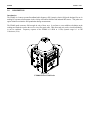
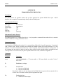
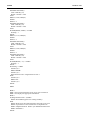
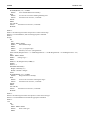
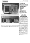
The FP4000 is a battery-operated broadband radio frequency (RF) isotropic electric field probe designed for use in
making RF exposure measurements in the vicinity of broadcast facilities and industrial RF sources. This probe uses
optical isolation to minimize field perturbation during measurements.
The FP4000 probe measures field strength in each of three axes. It performs a vector addition calculation on the
readings and sends the result to the receiver via a fiber optic cable. Data from each axis can be viewed individually,
or can be combined. Frequency response of the FP4000 is 10 KHz to 1 GHz; dynamic range is 1 to 300
Volts/meter (V/m).
Figure 1-1
FP4000 Electric Field Probe
FP4000
2.0
PAGE 2 of 30
FP4000 SPECIFICATIONS
Dynamic Range:
Ranges:
1 to 300 Volts/meter (V/m)
10, 30, 100, 300 Volts/meter full scale
Frequency Response:
10 KHz to 250 MHz ± 0.5 dB
250 MHz to 1.0 GHz ± 1.0 dB
Linearity:
± 0.5 dB full scale (F.S.): ± 2 least significant bits (LSBs) of A/D converter
Isotropicity:
± 0.5 dB
Overload Withstand:
1000 Volts/meter maximum, all ranges
Environmental:
Operating
Temperature:
Humidity:
10 ºC to 40 ºC (+50 ºF to +104 ºF)
5% to 95% relative humidity, non- condensing
Fiber Optic Cable
Connector:
Standard FSMA
Battery:
3.6 VDC, 1400 mA-h rechargeable Nickel-Cadmium (NiCd)
Battery Charger:
110/220 VAC, 16 hour
Probes:
64 mm (2.5 in) cube with probe shields on three sides
Probe Mount
¼ - 20 UNC tapped hole (internal thread) in base of probe
Weight:
0.4 Kg (14 oz.)
Optional Equipment:
See Table 5-1
FP4000
3.0
PAGE 3 of 30
ACCEPTANCE AND CONTROLS
Introduction
This section contains information on: unpacking and acceptance of the FP4000 probe; probe controls; probe
connectors; the battery, and; bench testing the battery charger.
Unpacking and Acceptance
Step 1.
Upon delivery of your order, inspect the shipping container(s) for evidence of damage. Record any
damage on the delivery receipt before signing. In case of concealed damage or loss, retain the
packing materials for inspection by the carrier.
Step 2.
Remove the probe from its shipping containers.
materials for future use.
Save the boxes and any protective packing
Step 3.
Check all materials against the packing list to verify that the equipment received matches that which
was ordered. If you find any discrepancies, note them and call Amplifier Research Customer
Service for further instructions.
Be sure that you are satisfied with the contents of your order and the condition of your equipment before installing
the probe.
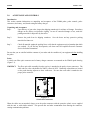
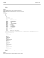
Probe
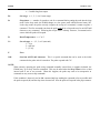
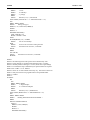
A switch, two fiber optic connectors and a battery charger connector are mounted on the FP4000 probe housing
(Figure 3-1).
XMIT/RCV
The fiber optic cable assembly from the receiver is attached to the probe via two connectors. The
cable ends are color-coded-white for XMIT, yellow for RCV. Identically-colored dots are located
on the probe housing adjacent to these connectors. Be sure that each cable is attached to the
proper probe connector.
Figure 3-1
Switch and Connectors
When the cables are not attached, always cover the probe connectors with the protective plastic covers supplied
with the unit, or with similar material. This prevents dirt and other contaminants from entering the connector,
causing communication problems.
FP4000
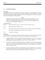
ARM/OFF
CHARGER
PAGE 4 of 30
The ARM/OFF switch activates and deactivates the probe. In the ARM position, the probe is
powered by its internal 3.6 VDC NiCd battery: in the OFF position, the probe is inactive. To
prolong battery life, set this switch to OFF when the probe is not in use.
An Amplifier Research BC2002 1 hour Fast Charger is supplied with the FP4000. The Amplifier
Research BC2002 manual details the specifications and use of this product.
Battery
The NiCd battery provides up to 40 hours of probe operation when fully charged.
FP4000
4.0
PAGE 5 of 30
BATTERY CHARGING
Introduction
Each FP4000 probe contains a rechargeable nickel-cadmium (NiCd) battery. A fully-charged battery (nominal
output voltage of 3.6 VDC) provides up to 40 hours of operation. When the battery has discharged to 3.3 VDC, the
probe is still operational, but its battery needs charging: when the voltage drops below 3.18 VDC, measurement
accuracy will be compromised by further operation.
NOTE
Amplifier Research charges the internal NiCd battery of the FP4000 at the factory in order to
calibrate the probe prior to shipment. While every effort is made to ensure that your probe arrives
ready to use, we cannot guarantee that this will be the case. Always check the condition of the
probe's battery prior to making any measurements.
Charging Procedure
Step 1.
Verify that the battery charger is set correctly for the AC voltage in your area.
Step 2.
Plug the charger into a suitable AC source.
Step 3.
Set the probe switch to OFF. Insert the plug on the charger cable into the probe's CHARGER jack.
The indicator on the charger lights up only when a probe is connected.
Step 4.
The battery is now charging.
Battery Tips
NiCd batteries have several characteristics that can affect both their performance and operating life. The following
tips advise you how to take advantage of these characteristics to get the most out of your probe's battery.
•
Although NiCd batteries are rated for operation in temperatures from -20 ºC to +65 ºC (-4 ºF to +140ºF),
operating the probe in extreme temperatures will reduce operating time significantly. The optimum
operating temperature range for these batteries is +20 ºC to +30 ºC (+68 ºF to +86 ºF).
•
The battery in the FP4000 does not require periodic "deep discharges" to reverse the capacity-depleting
"memory effect" caused by repeated shallow discharges; however, undercharging can reduce battery
capacity. Therefore, after the charging procedure is complete, be sure that the battery is fully charged
before resuming field operation.
•
If the battery exhibits low terminal voltage during charging, or if it appears unable to acquire or maintain an
appreciable charge, individual cells in the battery may be shorted or damaged. If, for any reason, your
battery needs replacement, contact Amplifier Research Customer Service for assistance.
FP4000
5.0
PAGE 6 of 30
MAINTENANCE
Introduction
This section explains which maintenance tasks can be performed by the user. It also provides information regarding
replacement and optional parts. If you have any questions concerning probe maintenance, consult Amplifier
Research Customer Service.
Maintenance Recommendations
Maintenance of the FP4000 is limited to external components such as cables or connectors.
Any calibration or maintenance task which requires probe disassembly should be performed at the factory. Check
with Amplifier Research Customer Service (215-723-0275) before opening the unit to avoid problems with your
probe's warranty.
NOTE
Opening the probe enclosure may void your warranty. If your system is under warranty, contact
Amplifier Research Customer Service before performing any maintenance inside the probe.
Return Procedures
To return a probe to Amplifier Research, use the following procedure:
Step 1.
Briefly describe the problem in writing. Give details regarding the observed symptom(s), and
whether the problem is constant or intermittent in nature. If you have talked previously to Amplifier
Research Customer Service about the problem, provide the date(s), the name of the service
representative you spoke with, and the nature of the conversation. Include the serial number of the
item being returned.
Step 2.
Package the probe carefully. Use the original boxes and packing materials, if possible.
NOTE
If your probe is calibrated in accordance with MIL-Std-45662A, it is greatly to your benefit to retain
the original shipping box and packing materials. One of the criteria for certifying a calibration to
MIL standards requires Amplifier Research to always ship equipment in the specified packaging.
When a MIL Standard instrument is sent to Amplifier Research in other packaging, we must
replace it with the specified packaging materials for return shipment. YOU WILL BE BILLED
FOR THE NEW PACKAGING.
If the probe is still under warranty, refer to the Limited Warranty in this manual for additional information about your
return.
Periodic/Preventive Maintenance
Amplifier Research recommends an annual calibration check of the FP4000 probe to verify that it is performing
within specifications. This calibration check may be performed by Amplifier Research. Contact Amplifier Research
Customer Service (215-723-0275) for price, scheduling and shipping information.
FP4000
PAGE 7 of 30
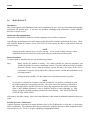
Parts Information
Use the following table (Table 5-1) for ordering replacement or optional parts for the FP4000.
Table 5-1. Replacement/Optional Parts List
Part Description (Replacement
Parts)
Universal 3.6V Fast Charger
(110/240 Volt) (BC2002)
FP4000 User's Manual
Cable, Fiber Optic, Glass, 10 Meter
(FP2010)
Probe Stand Assembly (PS2000)
Fiber Optic / RS232 Interface (IF4000)
Part Number
1010956-501
1007506
1004602-501
1005800-501
1007449-501
FP4000
6.0
PAGE 8 of 30
THEORY OF OPERATION
Introduction
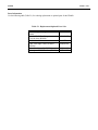
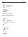
This section discusses the theory of operation and the functions of the FP4000 Isotropic Electric Field Probe. A
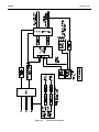
high-level block diagram (Figure 6-1) is included to aid the discussion. The objective is to provide information that
enhances the user's understanding of the design of this probe.
For detailed information on specific circuits, refer to the schematic diagram at the back of this manual.
System Theory
The FP4000 Isotropic Electric Field Probe utilizes a microprocessor for intelligent operation and control. The
probe's self-contained power supply employs a 3.6 VDC NiCd battery, which provides up to 40 hours of continuous
operation.
For each axis, the probe measures the radio frequency signal level and generates a linearized reading of the
measurement. A vector addition is performed on these three readings: the resultant is transmitted to the receiver
over glass fiber optic cables. The probe provides data via either a short form or long form output word. See
Appendix B for details on both output word formats.
Probe Operation
Receiver commands to the probe consist of the following:
• Send reading
• Zero
• Change range
• Enable/disable axis
• Read battery voltage
• Set sleep timer
• Read temperature
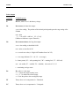
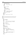
The signal flow within the probe is shown in the block diagram.
FP4000
PAGE 9 of 30
FP4000
PAGE 10 of 30
Figure 6-1
Probe Block Diagram
FP4000
PAGE 11 of 30
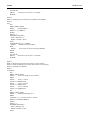
To measure field strength, three sets of mutually orthogonal monopole antennas are used to provide an isotropic
response to the ambient field. The probe uses two antennas per axis-one each for high and low frequencies-to
receive RF signals. The signals are fed to a Schottky diode detector (low frequency signals are preamplified first).
After filtering and amplification, the high and low frequency signals generated by each axis (a total of six signals)
are fed into the multiplexer.
The microprocessor instructs the multiplexer to look at each of the six axis signals sequentially. A time-division
output signal from the multiplexer is fed into the programmable gain stage.
The programmable gain stage provides the required amplification factors for the high and low frequency signals on
each range. The system uses four ranges (10, 30, 100, and 300 V/m): each range requires both a high and low
frequency gain setting-eight amplification factors in all.
For example, assume the probe is making measurements using the 100 V/m range. When the multiplexer selects the
low frequency X axis signal, the microprocessor directs the programmable gain stage to use the appropriate
amplification factor for this signal. This process is repeated for the next signal sample (X high) as well as for the
four remaining axis signals. The output of the gain stage feeds the multiplexed front end of the analog-to-digital
(A/D) converter.
After stepping through all six axis signals, the microprocessor commands the multiplexed A/D front end to read the
battery voltage and temperature sensing lines. An entire A/D cycle, therefore, consists of eight readings.
The eight readings from the A/D converter are input to the microprocessor, which performs a vector sum
calculation on the X, Y and Z channels. This data is transmitted.
Probe Power Supply
The probe is powered by a sealed rechargeable 3.6 VDC NiCd battery, which drives both the analog and digital
power supplies; the FP4000 employs separate power sources to provide isolation between the analog and digital
circuitry. With the probe switch in the ARM position, voltage from the battery is applied to the power switch. This
switch routes the battery voltage to the power supply, enabling the microprocessor. The power switch is controlled
by a timer circuit. The timer monitors the fiber optic connector input line to determine whether the probe has
received a command during a specified period (several seconds). If no command is received during this period, the
timer signals the power switch to disable the power supply and the microprocessor. In essence, the probe goes
dormant to conserve battery power: only the fiber optic input circuitry remains active in order to detect new
commands. When the next command reaches the probe, power is reapplied automatically and the processor is
reactivated, "waking up" the probe.
NOTE
The probe uses volatile random access memory (RAM). If, for any reason, power to the probe is
lost, the probe must be re-zeroed.
Zeroing
When the zero command is sent, the probe must be in a zero field environment. This is because the zero command
causes the multiplexer (via the processor) to perform a normal read cycle on all axis signals. This procedure is
executed for all 24 ranges (four ranges, three axes per range, two antennas per axis). When the processor receives
all the zero-field signal values, it stores them in a special register; these values are subtracted from all subsequent
measurements. Therefore, a probe which is zeroed while it is not in a zero field environment will give erroneous
readings.
FP4000
7.0
PAGE 12 of 30
APPLICATION CONSIDERATIONS
Introduction
The following subsections contain information designed to help you maximize the effectiveness of the FP4000 probe.
Out-of-Band Considerations
Although the specified operating range of the FP4000 is from 10 KHz to 1 GHz, it responds to signals both above
and below these frequencies. Such responses must be taken into account when performing certain operations, such
as zeroing.
On the low frequency end, the FP4000 is specified to operate down to 10 KHz; however, the probe can exhibit
some response to frequencies as low as 50/60 Hz. Such an out-of-band response poses a problem when zeroing the
unit, since this operation obviously assumes a zero field condition. Therefore, when zeroing, the user must
compensate accordingly for any low frequency out-of-band response.
At the upper end, similar problems can occur. The specified upper operating limit is 1 GHz. Above this frequency,
the dimensions of the probe body itself become appreciable in relation to wavelength: this makes the behavior of the
FP4000 unpredictable above 1 GHz. Responses to frequencies up to 6 GHz must be compensated for when zeroing
the probe.
Resolution Limitations
Limitations in system resolution may result in a non-zero reading when the receiver is zeroed. If this occurs, it does
not necessarily mean that your readings are inaccurate. Probe linearity is specified as ± 0.5 dB full scale: in addition,
the variance of the probe's A/D converter is ± 2 least significant bits. When using the most sensitive range (10
V/m), these specifications create the possibility that, under zero field conditions, the receiver may display a non-zero
value.
Probe Support Structures
It is very important to keep conductive objects away from the FP4000. Any such objects in the proximity of the
probe may distort the near field and compromise measurement accuracy. If your application requires measurements
from a fixed position, always mount the probe on a non-metallic platform, using non-metallic screws.
FP4000
PAGE 13 of 30
APPENDIX A
FP4000 ERROR CODES
Probe Error Output
If an error occurs, the probe will respond with one of the following strings. These strings begin with a colon and end
with a carriage return.
E01
Communication error (e.g., overflow).
E02
Buffer full error. Too many characters contained between the Start Character/Carriage Return sequence.
E03
The received command is not valid.
E04
The received parameter is not valid.
E05
Hardware error (e.g., EEPROM failure).
E06
Parity error.
FP4000
PAGE 14 of 30
APPENDIX B
FP4000 OPERATING PROTOCOLS
Introduction
The information in this appendix assumes that you have purchased the optional IF4000 Fiber Optic / RS232
Interface, and are capable of communicating directly with the FP4000 probe.
Communication Protocol
Data Type:
Data Mode:
Word Length:
Parity:
Stop Bits:
Data Rate:
RS-232 Serial
Asynchronous
7 bit
Odd
1
9600 baud
Information Transfer Protocol
The FP4000 operates as a Controller Mode device. It only responds to commands from another device; it transmits
no data without first receiving instructions to do so.
Command Structure
A command to an FP4000 probe consists of 1) a command letter, followed by 2) possible parameters, 3) terminated
with a carriage return. When it completes the command, the FP4000 responds with a string consisting of 1) a start
character (":"), 2) the command letter, followed by 3) data, if required, and terminated with 4) a carriage return. If
the command does not require the probe to return any data, the probe simply responds with the command letter and
a carriage return. If an error occurs, the probe responds with an error code, as detailed in Appendix A.
Commands
Command
Description
Axxx
Axis enable/disable. x = "E" means enable, x = "D" means disable. xxx order is X axis, Y
axis, Z axis
B
Read battery voltage.
Cx
Dx
Set baud rate.
x = 1 sets rate to 2400 baud
x = 2 sets rate to 9600 baud
Note that the baud rate does not change until the FP4000 has been powered down (turned off), let
sit for at least 10 seconds, and then powered up (turned on) again.
Read probe data.
x = 1 enables short form output
FP4000
PAGE 15 of 30
x = 2 enables long form output
Rx
Set range. x = 1, 2, 3, 4 or N (next range)
Sx
Sleep timer. x = number of seconds to wait for a command before putting the probe into the sleep
mode. In the sleep mode, the FP4000 changes to a low power mode which increases battery life.
In the sleep mode, the probe can only recognize the receipt of a command; it cannot recognize a
command. The first command sent when the probe could be in a sleep mode may be an ASCII null
character or any command. Following the receipt of this "wakeup" character, a command can be
sent to which the probe will respond.
Tx
Read Temperature. x = C or F
Ux
Set unit type. x = 1, 2, 3, or N (next unit)
1 = V/m
2 = mW/cm²
3 = [V/m]²
Z
Zero.
Null
Send the ASCII null character. This is a special command that can be used as the initial
command to the probe after it is turned on. The probe responds with "N".
NOTE:
When remotely operating the probe using commands manually entered from a computer keyboard, the
FP4000 may "go to sleep" between commands. This may be noted when the Sleep Timer is set to a short
interval such as one or two seconds. When this happens, the probe may seem to be unresponsive to
commands or may seem to skip commands.
If this condition is observed, send an S0 command and keep sending the command as fast as possible until
the probe responds (:S) and the sleep timer is turned off. Now the probe will respond in the proper manner.
FP4000
PAGE 16 of 30
Probe Output
Command
FP4000 Response
B
Bxx.xx, where xx.xx is the battery voltage.
D1
Dxx.xxuuu, the short form output.
xx.xx is the reading. The position of the decimal point depends upon the range setting of the
FP4000.
uuu = units
_V_ = V/m, mW2 = mW/cm², _V2 = [V/m]²
(underscore indicates a space character).
D2
Dxx.xxuuurrrobaaat, the long form output.
xx.xx = the reading, as described for D1.
uuu = units, as describe for D1.
rrr = recorder out value (A 3-digit ASCII number from 0 to 255).
o = over range indicator ("N" = ok, "O" = over range).
b = battery status ("N" = safe operating level, "W" = warning level, "F" = fail level).
aaa = axis enable ("E" = enabled, "D" = disabled). Axis order is X, Y, Z.
t = terminating carriage return.
Rx
Rx, where x is the range.
x = "" returns the range currently in use
x = 1, 2, 3, 4 enables the selected range
x = N sets the probe to the next (higher) range.
TF
Txxx, where xxx is temperature in º Fahrenheit.
TC
Txxx, where xxx is temperature in º Centigrade.
FP4000
PAGE 17 of 30
NOTE: "Compiled executable version available upon request"
APPENDIX C
FP4000 QUICKBASIC EXAMPLE COMMUNICATIONS PROGRAM
QuickBasic Code
'FP4000 Driver
'Version 1.0
REM **
REM ** the next lines open RS-232 for communication with FP4000
REM ** either on com1 or com2
REM **
DO
CLS
PRINT : PRINT : PRINT
PRINT "
Com port configuration for FP4000"
PRINT
PRINT "
1. COM1"
PRINT "
2. COM2"
PRINT
INPUT "
Selection (1-2)? ", ComSelect$
LOOP UNTIL (ComSelect$ = "1" OR ComSelect$ = "2")
SELECT CASE ComSelect$
CASE "1"
OPEN "COM1:9600,O,7,1,RS,CS0,DS0" FOR RANDOM AS #1
CASE "2"
OPEN "COM2:9600,O,7,1,RS,CS0,DS0" FOR RANDOM AS #1
END SELECT
REM
REM ** the next lines wake the FP4000 if it is currently in sleep
REM ** mode, and set the sleep timer to zero, which disables
REM ** the sleep timer.
REM **
PRINT : PRINT : PRINT
PRINT "
Setting up FP4000..."
PRINT
PRINT #1, "S0"; CHR$(13)
SLEEP 1
PRINT #1, "S0"; CHR$(13)
SLEEP 1
PRINT #1, "S0"; CHR$(13)
SLEEP 1
Result$ = ""
DO WHILE NOT EOF(1)
Sleep$ = INPUT$(1, #1)
Result$ = Result$ + Sleep$
FP4000
PAGE 18 of 30
LOOP
WIDTH #1, 255
REM **
REM ** The main menu lets you choose from the diagnostic routine or
REM ** the simple driver that takes data, etc.
REM **
MainMenu:
DO
DO
CLS
PRINT : PRINT : PRINT
PRINT "
FP4000 Main Menu"
PRINT
PRINT "
1. Diagnostics"
PRINT "
2. FP4000 Driver"
PRINT
INPUT "
Selection (1-2) or (Q)uit? ", MainChoice$
LOOP UNTIL ((MainChoice$ = "1") OR (MainChoice$ = "2") OR (MainChoice$ = "Q") OR (MainChoice$ = "q"))
SELECT CASE MainChoice$
CASE "1"
GOSUB Diagnostics
CASE "2"
GOSUB DriverMenu
CASE "Q"
GOTO Quit
CASE "q"
GOTO Quit
END SELECT
LOOP UNTIL (MainChoice$ = "Q" OR MainChoice$ = "q")
REM **
REM ** The diagnostic routine sends various commands and requests
REM ** responses to ensure that the FP4000 is working correctly, and
REM ** if errors are encountered, provides information about where
REM ** the problem may be occurring.
REM **
Diagnostics:
CLS
DiagnosticErrorCount = 0
PRINT
PRINT "Testing.........."
REM ** The next lines sends the command to receive battery
REM ** voltage and reads the serial port to ensure that the
REM ** correct response was given by the FP4000.
REM **
PRINT #1, "B"; CHR$(13)
PRINT "Battery Voltage: ";
SLEEP 1
Result$ = ""
DO WHILE NOT EOF(1)
Voltage$ = INPUT$(1, #1)
Result$ = Result$ + Voltage$
LOOP
IF INSTR(Result$, ":B") = 0 THEN
FP4000
COLOR 4, 0, 0
PRINT "ERROR"
COLOR 7, 0, 0
DiagnosticErrorCount = DiagnosticErrorCount + 1
ELSE
COLOR 2, 0, 0
PRINT "OK"
COLOR 7, 0, 0
END IF
REM **
REM ** The next lines test the temperature request command
REM **
PRINT #1, "TC"; CHR$(13)
PRINT "Temperature:
";
SLEEP 1
Result$ = ""
DO WHILE NOT EOF(1)
Temperature$ = INPUT$(1, #1)
Result$ = Result$ + Temperature$
LOOP
IF INSTR(Result$, ":T") = 0 THEN
COLOR 4, 0, 0
PRINT "ERROR"
COLOR 7, 0, 0
DiagnosticErrorCount = DiagnosticErrorCount + 1
ELSE
COLOR 2, 0, 0
PRINT "OK"
COLOR 7, 0, 0
END IF
REM **
REM ** The next lines test the zeroing command.
REM **
PRINT #1, "Z"; CHR$(13)
PRINT "Zero:
";
SLEEP 1
Result$ = ""
DO WHILE NOT EOF(1)
Zero$ = INPUT$(1, #1)
Result$ = Result$ + Zero$
LOOP
IF INSTR(Result$, ":E") <> 0 THEN
COLOR 4, 0, 0
PRINT "ERROR"
COLOR 7, 0, 0
DiagnosticErrorCount = DiagnosticErrorCount + 1
ELSE
COLOR 2, 0, 0
PRINT "OK"
COLOR 7, 0, 0
END IF
REM **
REM ** The following lines set the X, Y, and Z axis to a
PAGE 19 of 30
FP4000
REM ** particular setting, then checks to see if what was
REM ** expected happened. This is then repeated with a
REM ** different value and rechecked.
REM **
ErrorFlag = 0
AxisSend$ = "ADDD" + CHR$(13)
PRINT "Axis:
";
PRINT #1, AxisSend$
SLEEP 1
Result$ = ""
DO WHILE NOT EOF(1)
Axis$ = INPUT$(1, #1)
Result$ = Result$ + Axis$
LOOP
PRINT #1, "D2"; CHR$(13)
SLEEP 1
Result$ = ""
DO WHILE NOT EOF(1)
Axis$ = INPUT$(1, #1)
Result$ = Result$ + Axis$
LOOP
IF INSTR(Result$, "DDD") = 0 THEN
ErrorFlag = 1
END IF
AxisSend$ = "AEEE"
PRINT #1, AxisSend$; CHR$(13)
SLEEP 1
Result$ = ""
DO WHILE NOT EOF(1)
Axis$ = INPUT$(1, #1)
Result$ = Result$ + Axis$
LOOP
PRINT #1, "D2"; CHR$(13)
SLEEP 1
Result$ = ""
DO WHILE NOT EOF(1)
Axis$ = INPUT$(1, #1)
Result$ = Result$ + Axis$
LOOP
IF INSTR(Result$, "EEE") = 0 THEN
ErrorFlag = 1
END IF
IF ErrorFlag = 1 THEN
COLOR 4, 0, 0
PRINT "ERROR"
COLOR 7, 0, 0
DiagnosticErrorCount = DiagnosticErrorCount + 1
ELSE
COLOR 2, 0, 0
PRINT "OK"
COLOR 7, 0, 0
END IF
REM **
REM ** These next lines checks the range setting capability
REM ** with a similar method to the above routine for the axes.
PAGE 20 of 30
FP4000
REM **
PRINT #1, "R2"; CHR$(13)
PRINT "Range:
";
SLEEP 1
ErrorFlag = 0
Result$ = ""
DO WHILE NOT EOF(1)
Range$ = INPUT$(1, #1)
Result$ = Result$ + Range$
LOOP
PRINT #1, "R"; CHR$(13)
SLEEP 1
Result$ = ""
DO WHILE NOT EOF(1)
Range$ = INPUT$(1, #1)
Result$ = Result$ + Range$
LOOP
IF INSTR(Result$, "R2") = 0 THEN
ErrorFlag = 1
END IF
PRINT #1, "R1"; CHR$(13)
SLEEP 1
Result$ = ""
DO WHILE NOT EOF(1)
Range$ = INPUT$(1, #1)
Result$ = Result$ + Range$
LOOP
PRINT #1, "R"; CHR$(13)
SLEEP 1
Result$ = ""
DO WHILE NOT EOF(1)
Range$ = INPUT$(1, #1)
Result$ = Result$ + Range$
LOOP
IF INSTR(Result$, "R1") = 0 THEN
ErrorFlag = 1
END IF
IF ErrorFlag = 1 THEN
COLOR 4, 0, 0
PRINT "ERROR"
COLOR 7, 0, 0
DiagnosticErrorCount = DiagnosticErrorCount + 1
ELSE
COLOR 2, 0, 0
PRINT "OK"
COLOR 7, 0, 0
END IF
REM **
REM ** These next lines check the unit type setting command.
REM **
ErrorFlag = 0
PRINT #1, "U2"; CHR$(13)
PRINT "Unit Type:
";
SLEEP 1
Result$ = ""
PAGE 21 of 30
FP4000
DO WHILE NOT EOF(1)
Unit$ = INPUT$(1, #1)
Result$ = Result$ + Unit$
LOOP
PRINT #1, "D2"; CHR$(13)
SLEEP 1
Result$ = ""
DO WHILE NOT EOF(1)
Unit$ = INPUT$(1, #1)
Result$ = Result$ + Unit$
LOOP
IF INSTR(Result$, "MW2") = 0 THEN
ErrorFlag = 1
END IF
PRINT #1, "U1"; CHR$(13)
SLEEP 1
Result$ = ""
DO WHILE NOT EOF(1)
Unit$ = INPUT$(1, #1)
Result$ = Result$ + Unit$
LOOP
PRINT #1, "D2"; CHR$(13)
SLEEP 1
Result$ = ""
DO WHILE NOT EOF(1)
Unit$ = INPUT$(1, #1)
Result$ = Result$ + Unit$
LOOP
IF INSTR(Result$, " V ") = 0 THEN
ErrorFlag = 1
END IF
IF ErrorFlag = 1 THEN
COLOR 4, 0, 0
PRINT "ERROR"
COLOR 7, 0, 0
DiagnosticErrorCount = DiagnosticErrorCount + 1
ELSE
COLOR 2, 0, 0
PRINT "OK"
COLOR 7, 0, 0
END IF
PRINT
REM **
REM ** the next lines determines if any errors were encountered
REM ** and displays the appropriate information.
REM **
IF (DiagnosticErrorCount = 0) THEN
PRINT "This FP4000 appears to be working normally."
ELSE
PRINT "Please write down this information and contact your local"
PRINT "representative or the Customer Service department at"
PRINT "Amplifier Research. Refer to your FP4000 manual for that"
PRINT "information."
END IF
PAGE 22 of 30
FP4000
PAGE 23 of 30
PRINT
INPUT "Press Enter to return to the Main Menu.", Continue$
RETURN
REM **
REM ** the following lines display the choices available if the
REM ** selection for the driver was chosen, and processes the chosen
REM ** selection.
REM **
DriverMenu:
DO
DO
CLS
GOSUB InitVar
PRINT : PRINT : PRINT
PRINT "
FP4000 Driver Menu"
PRINT
PRINT "
1. Read battery voltage"
PRINT "
2. Read temperature"
PRINT "
3. Zero"
PRINT "
4. Axis enable/disable"
PRINT "
5. Set range"
PRINT "
6. Set unit type"
PRINT "
7. Read probe data"
PRINT "
8. Set sleep timer"
PRINT "
9. Set baud rate"
PRINT "
Q. Quit"
PRINT
INPUT "
Selection (1-9)? ", DriverChoice$
LOOP UNTIL (DriverChoice$ >= "1" AND DriverChoice$ <= "9" OR DriverChoice$ = "Q" OR DriverChoice$ = "q")
SELECT CASE DriverChoice$
CASE "1"
GOSUB Battery
CASE "2"
GOSUB Temperature
CASE "3"
GOSUB Zero
CASE "4"
GOSUB AxisEnable
CASE "5"
GOSUB Range
CASE "6"
GOSUB Unit
CASE "7"
GOSUB ReadData
CASE "8"
GOSUB SleepTimer
CASE "9"
GOSUB BaudRate
END SELECT
LOOP UNTIL (DriverChoice$ = "Q" OR DriverChoice$ = "q")
RETURN
REM **
REM ** the following lines request and display the battery voltage
FP4000
REM **
Battery:
CLS
PRINT : PRINT : PRINT
PRINT "
Requesting battery voltage from FP4000..."
PRINT
'Send battery volt request to FP4000
PRINT #1, "B"; CHR$(13)
SLEEP 1
PRINT "
Battery Voltage: ";
Result$ = ""
DO WHILE NOT EOF(1)
Voltage$ = INPUT$(1, #1)
Result$ = Result$ + Voltage$
LOOP
PRINT Result$: PRINT
PRINT
LOCATE 24, 1
INPUT "
Press Return to continue ", Continue$
RETURN
REM **
REM ** the following lines request and display the temperature
REM **
Temperature:
DO
CLS
PRINT : PRINT : PRINT
PRINT "
Request temperature"
PRINT
PRINT "
1. Temperature in Celsius"
PRINT "
2. Temperature in Fahrenheit"
PRINT
INPUT "
Selection (1-2)? ", TempChoice$
LOOP UNTIL (TempChoice$ = "1" OR TempChoice$ = "2")
CLS
PRINT : PRINT : PRINT
PRINT "
Requesting temperature from FP4000..."
PRINT
'Send temperature request to FP4000
SELECT CASE TempChoice$
CASE "1"
PRINT #1, "TC"; CHR$(13)
SLEEP 1
CASE "2"
PRINT #1, "TF"; CHR$(13)
SLEEP 1
END SELECT
PRINT "
Temperature: ";
Result$ = ""
DO WHILE NOT EOF(1)
Temperature$ = INPUT$(1, #1)
Result$ = Result$ + Temperature$
LOOP
PRINT Result$: PRINT
PRINT
PAGE 24 of 30
FP4000
LOCATE 24, 1
INPUT "
Press Return to continue ", Continue$
RETURN
REM **
REM ** the following lines send the zero command to the FP4000
REM **
Zero:
CLS
PRINT : PRINT : PRINT
PRINT "
Zeroing FP4000..."
PRINT #1, "Z"; CHR$(13)
SLEEP 1
Result$ = ""
DO WHILE NOT EOF(1)
Zero$ = INPUT$(1, #1)
Result$ = Result$ + Zero$
LOOP
IF INSTR(Result$, ":E") = 0 THEN
PRINT "
FP4000 zeroed successfully"
ELSE
PRINT "
An error has occurred in zeroing the FP4000"
END IF
PRINT
LOCATE 24, 1
INPUT "
Press Return to continue ", Continue$
RETURN
REM **
REM ** the following lines allow the operator to enter enable or
REM ** disable commands for each axis and sends the corresponding
REM ** command to the FP4000
REM **
AxisEnable:
CLS
PRINT : PRINT : PRINT
PRINT "
Type 'E' for enable or 'D' for disable"
PRINT
INPUT "
X axis: ", XAxis$
XAxis$ = UCASE$(XAxis$)
INPUT "
Y axis: ", YAxis$
YAxis$ = UCASE$(YAxis$)
INPUT "
Z axis: ", ZAxis$
ZAxis$ = UCASE$(ZAxis$)
CLS
PRINT : PRINT : PRINT
PRINT "
Enabling/disenabling axes..."
PRINT
AxisSend$ = "A" + XAxis$ + YAxis$ + ZAxis$
PRINT #1, AxisSend$; CHR$(13)
SLEEP 1
Result$ = ""
DO WHILE NOT EOF(1)
Axis $ = INPUT$(1, #1)
Result$ = Result$ + Axis$
LOOP
PAGE 25 of 30
FP4000
PAGE 26 of 30
IF INSTR(Result$, ":E") = 0 THEN
PRINT "
Axes enabled/disabled successfully"
ELSE
PRINT "
An error has occurred in enabling/disabling axes"
INPUT "
Press Return to continue ", Continue$
END IF
PRINT
LOCATE 24, 1
INPUT "
Press Return to continue ", Continue$
RETURN
REM **
REM ** the following lines allows the operator to choose which range
REM ** to set the FP4000 to, and sends the appropriate command.
REM **
Range:
DO
CLS
PRINT : PRINT : PRINT
PRINT "
Select FP4000 range"
PRINT
PRINT "
1, 2, 3, 4, or [N]ext range"
INPUT "
Selection (1-4 or N)? ", RangeChoice$
LOOP UNTIL (RangeChoice$ >= "1" AND RangeChoice$ <= "4" OR RangeChoice$ = "n" OR RangeChoice$ = "N")
CLS
PRINT : PRINT : PRINT
PRINT "
Setting range..."
PRINT
PRINT #1, "R"; RangeChoice$; CHR$(13)
SLEEP 1
Result$ = ""
DO WHILE NOT EOF(1)
Range$ = INPUT$(1, #1)
Result$ = Result$ + Range$
LOOP
IF INSTR(Result$, ":E") = 0 THEN
PRINT "
Range selected successfully"
ELSE
PRINT "
An error has occurred in selecting the range"
INPUT "
Press Return to continue ", Continue$
END IF
PRINT
LOCATE 24, 1
INPUT "
Press Return to continue ", Continue$
RETURN
REM **
REM ** the following lines allows the operator to select which unit type
REM ** to set the FP4000 to and sends the appropriate command.
REM **
Unit:
DO
CLS
PRINT : PRINT : PRINT
PRINT "
Select a unit type"
PRINT
FP4000
PRINT "
1. V/m"
PRINT "
2. mW/cmý"
PRINT "
3. [V/m]ý"
PRINT
INPUT "
Selection (1-3)? ", UnitChoice$
LOOP UNTIL (UnitChoice$ >= "1" AND UnitChoice$ <= "3")
CLS
PRINT : PRINT : PRINT
PRINT "
Setting unit type..."
PRINT #1, "U"; UnitChoice$; CHR$(13)
SLEEP 1
Result$ = ""
DO WHILE NOT EOF(1)
Unit$ = INPUT$(1, #1)
Result$ = Result$ + Unit$
LOOP
IF INSTR(Result$, ":E") = 0 THEN
PRINT "
Unit set successfully"
ELSE
PRINT "
An error has occurred in setting the unit"
INPUT "
Press Return to continue ", Continue$
END IF
PRINT
LOCATE 24, 1
INPUT "
Press Return to continue ", Continue$
RETURN
REM **
REM ** the following lines let the operator select whether they want
REM ** single readings or continuous data from the probe. Currently,
REM ** the delay between readings is 1 second, but if more rapid readings
REM ** are needed, the sleep command may be replaced with a for loop like
REM ** this: FOR I = 1 to X : NEXT I
REM ** where "X" is some number which may vary. Note that too short of a
REM ** delay will cause erratic program behavior and possible buffer
REM ** overflow.
REM **
ReadData:
DO
CLS
PRINT : PRINT : PRINT
PRINT "
1. Single sample"
PRINT "
2. Continuous samples"
PRINT
INPUT "
Selection (1-2)? ", ReadChoice$
LOOP UNTIL (ReadChoice$ = "1" OR ReadChoice$ = "2")
CLS
PRINT : PRINT : PRINT
PRINT "
Reading field measurement from FP4000..."
PRINT
SELECT CASE ReadChoice$
CASE "1"
PRINT #1, "D2"; CHR$(13)
SLEEP 1
Result$ = ""
DO WHILE NOT EOF(1)
PAGE 27 of 30
FP4000
ReadData$ = INPUT$(1, #1)
Result$ = Result$ + ReadData$
LOOP
PRINT "
Reading from FP4000: ", Result$
CASE "2"
DO
PRINT #1, "D2"; CHR$(13)
SLEEP 1
Result$ = ""
DO WHILE NOT EOF(1)
ReadData$ = INPUT$(1, #1)
Result$ = Result$ + ReadData$
LOOP
LOCATE 6, 1
PRINT "
Reading from FP4000: "; Result$
PRINT "
Press ESC to stop readings."
LOOP UNTIL INKEY$ = CHR$(27)
END SELECT
PRINT
LOCATE 24, 1
INPUT "
Press Return to continue ", Continue$
RETURN
REM **
REM ** the following lines allow the operator to type a number (in seconds)
REM ** of inactivity that the FP4000 will wait before entering sleep mode.
REM **
SleepTimer:
CLS
PRINT : PRINT : PRINT
PRINT "
Sleep Timer"
PRINT
PRINT "
Enter time in seconds to wait for a command before"
INPUT "
putting the probe into sleep mode: ", SleepTime$
CLS
PRINT : PRINT : PRINT
PRINT "
Setting sleep timer..."
PRINT
PRINT #1, "S"; SleepTime$; CHR$(13)
SLEEP 1
Result$ = ""
DO WHILE NOT EOF(1)
Sleep$ = INPUT$(1, #1)
Result$ = Result$ + Sleep$
LOOP
IF INSTR(Result$, ":E") = 0 THEN
PRINT "
Sleep timer set successfully"
PRINT "
A setting that is too low will cause erratic "
PRINT "
program behavior. A reccommended setting is"
PRINT "
around 100."
ELSE
PRINT "
An error has occurred in seeting the sleep timer"
INPUT "
Press Return to continue ", Continue$
GOTO SleepTimer
END IF
PRINT
PAGE 28 of 30
FP4000
LOCATE 24, 1
INPUT "
Press Return to continue ", Continue$
RETURN
REM **
REM ** the following lines allow the operator to choose between a baud
REM ** rate of 2400 or 9600 for the next power up. Note that this program
REM ** opens the serial port for 9600 baud, so if 2400 is desired, the
REM ** OPEN statement in the setup routine at the beginning of this
REM ** program must be modified to accomodate for the baud rate change.
REM **
BaudRate:
DO
CLS
PRINT : PRINT : PRINT
PRINT "
Select a baud rate"
PRINT
PRINT "
1. 2400"
PRINT "
2. 9600"
PRINT
INPUT "
Selection (1-2)? ", BaudChoice$
LOOP UNTIL (BaudChoice$ >= "1" AND BaudChoice$ <= "2")
CLS
PRINT : PRINT : PRINT
PRINT "
Setting baud rate..."
PRINT #1, "C"; BaudChoice$; CHR$(13)
Result$ = ""
DO WHILE NOT EOF(1)
Baud$ = INPUT$(1, #1)
Result$ = Result$ + Baud$
LOOP
IF INSTR(Result$, ":E") = 0 THEN
PRINT "
Baud rate set successfully."
PRINT "
Note that the baud rate does not change until the"
PRINT "
FP4000 has been powered down (turned off), let sit"
PRINT "
for at least 10 seconds, and then powered up again."
PRINT "
Also note that this program configures the serial "
PRINT "
port to communicate at 9600 baud. If you wish to "
PRINT "
operate the FP4000 at 2400 baud, you will need to "
PRINT "
Change the OPEN statement to be as follows"
PRINT "
OPEN 'COM1:2400,O,7,1,RS,CD0,DS0'"
ELSE
PRINT "
An error has occurred in setting the baud rate"
INPUT "
Press Return to continue ", Continue$
GOTO BaudRate
END IF
PRINT
LOCATE 24, 1
INPUT "
Press Return to continue ", Continue$
RETURN
REM **
REM ** the following lines initialize sever program variables
REM **
InitVar:
MainChoice$ = ""
PAGE 29 of 30
FP4000
Result$ = ""
Voltage$ = ""
TempChoice$ = ""
Temperature$ = ""
Zero$ = ""
XAxis$ = ""
YAxis$ = ""
ZAxis$ = ""
AxisSend$ = ""
Axis$ = ""
RangeChoice$ = ""
Range$ = ""
UnitChoice$ = ""
Unit$ = ""
ReadChoice$ = ""
ReadData$ = ""
SleepTime$ = ""
Sleep$ = ""
BaudChoice$ = ""
Baud$ = ""
RETURN
REM **
REM ** the following lines close the serial port and end the program
REM **
Quit:
CLS
CLOSE
END
PAGE 30 of 30
FP4000
8.0
PAGE 31 of 30
SCHEMATICS