1
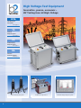
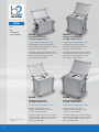
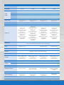
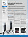
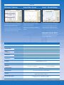
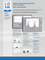
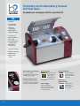
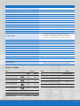
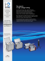
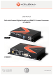
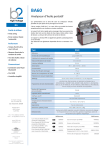
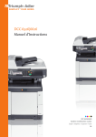
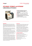
High Voltage Test Equipment Product Catalogue High Voltage Test Equipment Innovative, proven, economic – HV Testing from b2 High Voltage HVA VLF-High Voltage Test Systems from page 3… TD Tan Delta Diagnostic System from page 6… PD Partial Discharge Diagnostic System from page 8… BA Oil Tester – Breakdown Analyzer from page 10… HVA 30 HVA 60 Tan Delta Diagnostic Systems 2 Breakdown Analyzer BA75 Partial Discharge Diagnostic System VLF High Voltage Test Equipment – the HVA-Series The most sold, advanced, safest, smallest and lightest – a class of its own ! b2 electronic GmbH is a globally represented company based in Austria specialising in high voltage test and diagnostic products for the world’s electricity distribution network companies and their supporting industries such as generation and construction. b2 electronic incorporates several decades of experience in developing and producing high voltage test sets and diagnostic systems for MV cables. Several hundred “Very Low Frequency” (VLF – 0.1 Hz) test sets sold into the global market provide us with an impressive reference. b2 electronic is the most successful European manufacturer of sine wave VLF test sets by a significant margin. More efficiency through VLF It is well known that DC testing of aged extruded cable such as XLPE and EPR is potentially damaging to the cable insulation, causing premature failure of the cable under service conditions, thus leading to major costs and CML (customer minutes lost). In addition, DC “proof” or “hipot” testing has been found to be largely ineffective in detecting serious defects in cables. Since this is a primary objective of any hipot test, and also due to the negative side effects of DC, VLF AC waveform testing is now recommended by almost all new cable testing policies and standards. Acceptance or maintenance hipot / proof testing using VLF high voltage sinusoidal AC allows the operator to efficiently detect serious cable insulation defects before they result in an in-service failure, without affecting those healthy sections of the cable that still have remaining service life. Very low frequency (VLF) AC (0.1 Hz) voltage testing is now the recommended and required method of test for medium-voltage cables. (e.g. CENELEC HD620 S1, IEEE 400.2, VDE 0276, …) HVA advantages at a glance • VLF (0.1Hz), DC (±), Cable Fault Conditioning (Burning), and Sheath/Jacket Testing modes all included. • Vacuum Bottle Test • Fully automatic or manual cable test sequences complying with international standards & guides such as IEEE 400.2, VDE 0276, CENELEC, HD620 S1, NEN 3620, SANS 10198 and IEC 60060-3 (draft). • True symmetrical sinusoidal, load independent output waveform across the full load range. • RMS digital metering of current and voltage and measuring of resistance and capacitance. • Storage of test results for later retrieval or download to a PC/Laptop. • No oil filled devices, or arcing contactors that require routine maintenance. • Large output load capability. • Short circuit protected with active arc management regulation that avoids the tripping of conventional HV test equipment when a dielectric failure occurs. • Automatic and integrated. load capacitance measurement with optimum frequency selection. • Upgradeable to a Cable Diagnostic System, such as Tan Delta (TD) and Partial Discharge. HVA safety features HVA Applications • Short circuit protected • Cables: XLPE, PE, EPR, PILC etc. • Solid and fully integrated discharge circuit to safely ground the DUT (Device Under Test) after testing • Capacitors • Unique and essential real-time display of actual output waveform. HVA: VLF Testing – fully equipped ! The HVA series are the most advanced HV VLF AC/DC test sets in the world. They are the lightest and most compact instruments of their kind. The HVA models also have the highest power to weight ratio of any comparable units. Apart from their variable frequency VLF output, the operator can also select dual polarity DC and cable jacket or sheath testing output modes. The applied test voltage, current, capacitance, resistance and time are both displayed and recorded. The instruments are easily programmable allowing the operator to set up or select test sequences in either automatic or manual mode. To assist the operator, the instruments will automatically calculate the optimum frequency to be selected for larger loads. Their load independent, symmetrical output waveform avoids the potentially destructive space charge effects caused by DC polarization that occur in aged extruded cables such as XLPE / PE / EPR, causing them to fail prematurely after exposure to conventional high voltage DC or from a test instrument with large non-symmetrical output waveforms. Should a breakdown occur during testing, the actual voltage at which it occurred is displayed and recorded. If cable burning (fault conditioning) mode is activated, the fault resistance can be conditioned to allow easier and less stressful fault location techniques to be applied. The test results are stored in the instrument’s internal memory allowing easy retrieval and download to a PC via cable or via USB memory stick. • Status display of all important safety functions and messages • 12kV feedback protection (HVA30, HVA60, HVA90) • Switchgear • Transformers • Rotating Machines (IEEE 433) • Insulators • Bushings • Safe, easy to use operation with emergency off and key switch lock-out • Zero start interlock • Zero voltage switching 3 HVA • VLF • DC • Jacket/Sheath • Fault conditioning * at lower frequency and voltage 4 HVA30 HVA30-5 Portable and universal VLF High Voltage Test Set Portable and high power VLF High Voltage Test Set • Large output load capability up to 12 µF* • Large output load capability up to 15 µF* The ultra light HVA30 Test System with only 19.5 kg is capable of testing cables up to 1,500 m (0.5 µF at 0.1 Hz and 23 kV rms). The high power HVA30-5 Test System is capable of testing cables up to 10,000m (3.4 µF at 0.1 Hz and 23 kV rms). The variable output frequency allows the testing of even much longer cables. At 2.5 µF – 0.01 Hz and 23 kV rms a length of approx. 8,000 m can be tested (see technical data). The variable output frequency allows the testing of even much longer cables. At 15 µF – 0.02 Hz and 23 kV rms a length of approx. 45,000 m can be tested (see technical data). HVA60 HVA90 Portable and universal VLF High Voltage Test Set Compact and universal VLF High Voltage Test Set • Large output load capability up to 10 µF* • Large output load capability up to 10 µF* The high power HVA60 Test System is capable of testing cables up to 3,000 m (1 µF at 0.1 Hz and 44 kV rms). The high power HVA90 Test System is capable of testing cables up to 3,300m (1 µF at 0.1 Hz and 64 kV rms). The variable output frequency allows the testing of even much longer cables. At 5 µF – 0.01 Hz and 44 kV rms a length of approx. 15,000 m can be tested (see technical data). The variable output frequency allows the testing of even much longer cables. At 5 µF – 0.01 Hz and 64 kV rms a length of approx. 33,000 m can be tested (see technical data). Type HVA30 HVA30-5 HVA60 HVA90 Article number SH0201 SH0206 SH0203 SH0209 110 - 230 V 50 / 60 Hz (400 VA) 110 - 240 V 50 / 60 Hz (1.5 kVA) 110 - 240 V 50 / 60Hz (1.5 kVA) 210 - 265 V 50 Hz (3.0 kVA) 0 - 33 kV peak, 23 kV rms 0 - 33 kV peak, 23 kV rms 0 - 62 kV peak, 44 kV rms 0 - 90kV peak, 64 kV rms ± 0 - 30 kV ± 0 - 30 kV ± 0 - 60 kV ± 0 - 90 kV Squarewave 30 kV 30 kV 60 kV 90 kV Accuracy ±1% ±1% ±1% ±1% Resolution 0.1 kV 0.1 kV 0.1 kV 0.1 kV 0 - 15 mA (Resolution 1 µA) Accuracy: ± 1 % 0 - 85 mA (Resolution 1 µA) Accuracy: ± 1 % 0 - 40 mA (Resolution 1 µA) Accuracy: ± 1 % 0 - 60 mA (Resolution 1 µA) Accuracy: ± 1 % Input Voltage Sinusoidal DC Output Voltage Output Current Resistance Range 0.1 MΩ ….5 GΩ Output Frequency 0.01 … 0.1 Hz in steps of 0.01 Hz (default 0.1 Hz) – auto frequency selection 0.5 µF @ 0.1 Hz @ 23 kV rms (Approx 1.5 km of cable)* 1.0 µF @ 0.05 Hz @ 23 kV rms (Approx 3 km of cable)* Output Load 2.5 µF @ 0.02 Hz @ 23 kV rms (Approx 8 km of cable)* 12.0 µF maximum Capacitance 3.4 µF @ 0.1 Hz @ 23 kV rms (Approx 11 km of cable) 5 µF @ 0.1 Hz @ 19 kV rms (Approx 17 km of cable)* 6.25 µF @ 0.08 Hz @ 19 kV rms (Approx 20 km of cable)* 10 µF @ 0.05 Hz @ 19 kV rms (Approx 33 km of cable)* 15 µF maximum Capacitance 1.0 µF @ 0.1 Hz @ 44 kV rms (Approx 3 km of cable)* 1.0 µF @ 0.1 Hz @ 64 kV rms (Approx 3.3 km of cable)* 2.0 µF @ 0.05 Hz @ 44 kV rms (Approx 6 km of cable)* 1,2 µF @ 0.1 Hz @ 57 kV rms (Approx 3.6 km of cable)* 5.0 µF @ 0.02 Hz @ 44 kV rms (Approx 15.5 km of cable)* 10 µF @ 0.01 Hz @ 64 kV rms (Approx 33 km of cable)* 10 µF Maximum Capacitance 11 µF Maximum Capacitance AC (VLF) Symmetrical and load independent across full range, DC (plus or negative polarity), Burn / Fault Condition or Fault Trip Mode, Jacket / Sheath Testing Output Modes 50 Hz 12 kV Feedback Protection Safety 50 Hz 12 kV Feedback Protection – Memory 50 Test Records Stored Metering Voltage and Current (True rms and/or peak), Capacitance, Resistance, Time, Flashover Voltage Duty Continuous! No thermal limitation for operating time. 4.5 m (15’) with Alligator clamps on end (other options available on request) HV Cable 4.5 m (15’) with Alligator clamps on end (other options available on request) Software Computer interfaces 50 Hz 12 kV Feedback Protection 5 m (15’) with Alligator clamps on end (other options available on request) 7.5 m (15’) with Alligator clamps on end (other options available on request) “HVA Control Center” RS232 USB Flash Drive Optional Optional Optional Environmental conditions Dimensions L x W x H Weight Upgrades (Optional) Storage: -25 °C to +70 °C, Operating: -5 °C to +45 °C 430 x 250 x 360 mm 450 x 340 x 520 mm (Excludes Carry Handle) 450 x 340 x 520 mm 545 x 445 x 610 mm (Excludes Carry Handle), also as 19" version available 19,5 kg 45 kg 57 kg 127 kg Tan Delta System TD30 and Partial Discharge System PD30 Tan Delta System TD30 and Partial Discharge System PD30 Tan Delta System TD60 and Partial Discharge System PD60 Partial Discharge System PD90 * Based on a typical cable: 300 pF / m 5 Tan Delta Test System High Voltage Cable Diagnostic Systems TD30 and TD60 TD • Tan Delta • Ultra light and compact design • Easy handling • Testing and diagnostics simultaneously • Transfer of test results via Bluetooth • Fully automatic reporting • No complicated wiring Tan Delta measurement is a proven, simple and reliable test method for confirming the dielectric condition of cables or other electrical plant and infrastructure. “Water-tree” damaged cables can be easily and clearly be identified. The ease of use, low weight and the compact elegant design is truly impressive. The HVA series vlf test sets serve as the ideal high voltage source for these TD units. Applications Benefits Design The TD30 and TD60 provide the testing and commissioning engineer with versatile high voltage tan delta measurement systems suitable for testing XLPE, PE, EPR and PILC cables plus other electrical equipment such as capacitors, switchgear, transformers and rotating machines. TD testing enables the cable test engineer to detect insulation defects before the cable fails in service. It is far more informative than pressure testing alone and adds even more value to the market leading HVA series AC test sets. b2 electronic produce two models, the TD30 for measurements up to max voltage of 23 kV rms (33 kV peak), and the TD60 for measurements up to a max voltage of 44 kV rms (or 62 kV peak). Description Tan Delta (also referred to as “Power Factor”) is the ratio of the Resistive Power versus the Capacitive Power dissipated in the dielectric material during testing or when in actual service. It is possibly the single most reliable and sensitive measurement of the quality of the insulation medium available. As TD is an AC test all the benefits of VLF testing are inherent and the test is very quick as there are no DC charging times, or problems with dielectric absorption etc. The Tan Delta of the test object can be measured quickly and the results stored, thus providing a “signature” of the cable being tested. This enables the cables engineer to make a routine test and combine this diagnostic test with the normal over voltage pressure “testing” to provide a truly “smart” VLF test. When carried out at fixed intervals TD testing can be the basis of predictive maintenance program for your HV cables. Transportbox TD30 6 The system is battery powered and directly connected to an HVA series of VLF test sets. The TD30 / TD60 use standard C type alkaline batteries which last for 10 hours thus providing the capacity for many tests. The TD30 / TD60 are supplied with 5 / 7 metres of test lead which is terminated to suit the HVA30 / HVA60 units. It also comes with complete operating software which gives an immediate and comprehensive picture of the tan delta measurement together with a real time waveform display of the HV test voltage and current. The data transmission to a laptop PC is via Bluetooth™ wireless communication thus eliminating data cables or fibre optic links, minimising the connection time and possible operator errors. Transportbox TD60 Software TD Analysis Soware Output Wave Screen Graph – TD and Voltage The diagnostic report of the analysing software “TD Control Centre” presents a comprehensive and clear record of the individual measurements made during a TD test cycle. In the waveform screen both the output voltage and output current are displayed simultaneously in real time. In the TD graph the Tan Delta values at the corresponding voltage levels are displayed. An easy to interpret graphical display of the values offers a fast and accurate assessment of the dielectric condition of the cable. In addition to the status of the voltage and current waveforms, the Tan Delta value is also displayed. The TD values plotted against the HV test voltage values give an indication of the specific problems the cable insulation has. Automatic Report Writer At the click of your mouse the full Tan Delta report with all values, mean values and TD profile graph is printed. Type TD30 TD60 Article number SH0207 SH0208 Input Voltage 2 type “C” alkaline cells or NiMH batteries Sinusoidal 1 - 23 kV rms 1- 44 kV rms Frequency 0.1 Hz 0.1 Hz Operating Voltage Voltage measurement Resolution 0.1 kV rms Accuracy 1 % of reading Current measurement Resolution 1µA rms Accuracy 1 % of reading Tan delta measurement Resolution 1 x 10⁻⁵ Accuracy ± 1 x 10⁻⁴ (load > 15 nF), ± 3 x 10⁻⁴ (load < 15 nF) Standard: 15 nF to 5 µF; Lower Accuracy: 1 nF to 15 nF Load range Weight Dimensions Computer interface Delivery includes Standards Environmental conditions 3 kg (7 lbs) 5 kg (11 lbs) 240 mm long x 80 mm in diameter (9.5” long x 3.2” in diameter) 450 mm long x 120 mm in diameter (18” long x 5” in diameter) Bluetooth™ HV connection cable, transit case, Bluetooth™ Dongle, Earth cable, TD Control Center Software, Operating manual EMC: IEC6100-4-2, IEC6100-4-4, EN55011; Safety: EN60950, EN50191, EN61010-1 Storage: -25 °C to +70 °C, Operating: -5 °C bis +45 °C; Humidity max. 80 % R.H. (non-condensing) 7 Partial Discharge Detection and Location PD30, PD60 and PD90 PD • Comprehensive PC software Partial Discharge measurements have traditionally been carried out in a noise free environment such as a Faraday Cage. In the past this made on site P.D. measurement impossible. With the advent of modern electronics and digital filtering, it is now possible to effectively carry out Partial Discharge measurements in an electrical substation. • Complete cable length display with PD activities • High noise reduction • PD location – PD map • PD magnitude Today P.D. diagnostics provides the technician with a nondestructive means of evaluating the cable and the accessories. By locating these P.D. sites promptly, corrective measures can be taken before the cable fails thus avoiding power failures and customer minutes lost. P.D. Detection includes the following: • PD discharge metering • Phase position of discharges indicated • Scope display – sine wave superimposed • PD mapping – actual locations of partial discharges. • Locates sites using TDR principles The soware will record: • pC magnitude over time • Plot the P.D. map (location) • Plot the P.D. intensity The following parameters are recorded: • Calibration Pulse and End Detection (in accordance with IEC60270) • Voltage measurement circuit • Background Noise • PDIV (Partial Discharge Inception Voltage) • Partial Discharge level at 1.7 U0 • PDEV Partial Discharge Extinction Voltage 8 Type Rated Voltage kV peak HV Filter and Coupling Capacitor PD30 PD60 PD90 33 62 90 Rated Current (amps) Filter Capacitance (nF) Dimension L x H x B (mm) Weight (kg) 1 20 10 10 550 x 680 x 250 550 x 800 x 360 550 x 900 x 360 30 45 55 Display pC 100 to 10.000 Weight (kg) 1 Calibrator Display / Resolution (Pixel) Partial Discharge Detector Backlit LCD / 128 x 240 Input Impedance 10 kΩ / 50 pF Lower Cut-off (kHz) 40, 80 or 100 Upper Cut-off (kHz) 250, 600 or 800 Synchronisation (Hz) 0.1, 0.05, 0.02 Auto Zero Crossing Triggered Noise Dimensions L x H x B (mm) Yes Manual and Auto 250 x 150 x 300 Weight (kg) Microsoft Windows 3 XP / Windows7 Software PD Mapping and Location Two different models are available, one using a stand-alone independent PD detector/display unit, or the alternative version where signals are displayed and evaluated only on a PC via a Bluetooth connection. Yes The software automatically scans, records, edits, replays and allows the printing of the Partial Discharge screens. Zoom and cursor functions are provided for precision PD location and PD mapping. 9 Portable and laboratory based Oil Test Sets Breakdown Analyzer BA75 and BA100 BA Usability • Low weight and compact design • Ultra bright colour display • Internal battery, external 12V Supply Technology • Ultra fast switch-off time (< 5µS) • Direct measurement of output voltage • Measurement of silicone oils Communications • Bluetooth connection • USB flash drive • Intuitive control concept Ultra Bright Colour Display BA Technology The 2,8“ colour display is very bright and offers optimal readability and mobility. Ultra fast switch-off time at flash over (<5μs). Direct measurement of output voltage Measurement of silicon oils. Weight and Dimensions The BA Breakdown Analyzer is the smallest and lightest portable oil test set of its rating available. Power supply Besides main supply, the BA Series has a built-in battery pack and an external 12 V power supply. 10 Direct evaluation The built-in printer offer a direct evaluation and reporting of the results. Bluetooth / USB Flash Drive Communications via Bluetooth and/or USB Flash Drive possible. Type BA75 BA100 Article number SB0001 SB0005 Output Voltage Up to 75 kV rms symetrical Up to 100 kV rms symetrical Voltage measurement accuracy 0 … 75 kV } ±1 kV Voltage rise rate 0.5…10 kV/s Resolution (displayed) 0.1 kV Power supply 85 V … 264 V (47 Hz … 63 Hz) and 12 V external supply Power consumption 60 VA 75 VA Internal rechargeable battery 1 x 12V / 7,2Ah Switch-off time on flashover < 5 μs Measurement of oil temperature 0 … 100 °C Temperature resolution 1 °C Display 2,8” colour (ultra bright) VDE370-5/96, ÖVE EN60156, IEC 60156/95, ASTM1816-04-1, ASTM1816-04-2, ASTM877-02A, ASTM877-02B, AS1767.2.1, BS EN60156, NEN 10 156, NF EN60156, PA SEV EN60156, SABS EN60156, UNE EN60156, single measurement, other standards possible Selectable programs Customer-specific programs unlimited PC Software “BA75 Control Center” included Printer graphical output 44 mm (dot matrix) Interface Bluetooth USB USB memory stick Operating temperature -5° … 45 °C Storage temperature -20 … +60 °C Relative humidity Non condensing Dimensions W x H x D 430 x 280 x 250 mm 521 x 343 x 300 mm Weight 22 kg including batteries 32 kg including batteries Delivery includes Breakdown Analyzer BA, Lifting stick for magnetic stirrer, Printer, Magnetic oil stirrer, Setting gauge 2.5 mm IEC, User manual Scope of supply Article for Test vessel IEC 60 156 with cover and electrodes Test vessel IEC 60 156 with cover and electrodes number Article BA75 BA100 GB0050 GB0058 for Setting gauge 1 or 2 or 2,5 or 4 or 5 mm GB0051 GB0055 Test vessel ASTM D 877 with cover and electrodes GB0052 GB0056 Test vessel ASTM D 1816-04 with cover and electrodes GB0053 GB0057 Transport bag VKR0011 VKR0014 Dust cover VKR0016 VKR0017 Rugged Transport box VKR0010 VKR0015 number BA75 and BA100 GB0110-0114 Ring nut wrench (test vessel) GB0106 Lead for connecting vehicle cigarette lighter socket (12V, 5m) GB0120 Ribbon cartridge for printer GB0103 Paper roll for printer GB0102 11 The experts in high voltage testing b2 High-Voltage is a business division of b2 electronic GmbH Riedstraße 1 6833 Klaus AUSTRIA Tel. +43 (0)5523 57373 Fax +43 (0)5523 57373-5 www.b2hv.at [email protected] Norsk importør: www.Detektor.no DHV1200 Rev01 Names of goods are used without guarantee of free usage keeping to the manufacturer’s syntax. The names of goods used are registered and should be considered as such. EN ISO 9001 Zertifikat Nr. 20 100 92003758 Electricity means energy security – anytime and anywhere: Health, transport, security, manufacturing, telecommunications, infrastructure, logistics, research and entertainment – without continuous and failure resistant energy supplies around the clock, our modern civilization is hardly imaginable. With our high voltage test equipment products we support the electrical utilities maintenance of their electrical networks, so that whenever and wherever the energy is required it will be delivered. From portable High Voltage Test Systems to insulating oil testers – our test technology product solutions are first choice with customers worldwide who need to ensure a fail-safe power supply.