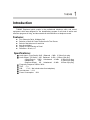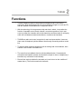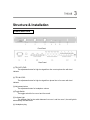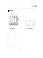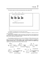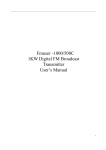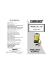
1
Operating Manual
Telephone Hybrid
F U TH804B (2010)
Broadcast System Equipment
Version 2.0
Attention!!
Thank you for purchasing our product!
Please read through this manual before the appliance is operated in order to know how
to use the appliance correctly. The manual should be retained for further reference.
Suzhou Fortune Technology Co., Ltd persists in sustainable strategy. Part of the
additional or revised functions does not included in the manual; please pay attention to
additional announcement.
Please refer to the latest user manual in the following website:
http://www.fmuser.net
Service Hotline:
Model:
Description:
Software Version:
Hardware Version:
Product No.:
Safety Instructions
Please read the following simple rules.
Breaking these rules will probably lead to
risk and violation laws. This manual
provides detail information about safety
instructions.
Caution: To reduce the risk of electrical
shock, do not remove cover. No
user serviceable parts inside.
Refer servicing to qualified
service personnel.
Warning: To reduce the risk of fire or
electrical shock, do not expose
this appliance to rain or moisture.
Symbol Illustration
The lightning flash with
arrowhead
symbol,
within an equilateral
triangle is intended to
alert the user to the
presence
of
non-insulated dangerous voltage within the
product’s enclosure that may be of sufficient
magnitude to constitute a risk of electric
shock to persons.
The exclamation point
within an equilateral
triangle is intended to
alert the user to the
presence of important
operating
and
maintenance (servicing)
instructions in the literature accompanying
the appliance.
Important Notice
All the safety and operating instructions should be read before the appliance is operated.
The safety and operating instruction should be retained for further reference.
Warning
To reduce the risk of electrical shock, short circuit, damage, fire and
other dangers, make sure to follow the following instructions which may
not cover all.
Important Safety Instructions
●
●
All the safety and operating
instructions should be read and
followed before the appliance is
operated and retained for future
reference.
Pay attention to all the warnings in
the operating manual.
Power & Power Cord
●
●
●
●
●
The appliance should be operated
under the power supply only of the
voltage described in the operating
instructions or as marked in the
power connector.
Do not plug or unplug the power
plug with wet hands.
Only use the qualified fuse.
Use the cable only of the type
described
in
the
operating
instructions.
Do not touch the bare cable or
circuit.
●
Please unplug the application if not
using it for a long time
Operation/ Location
●
●
●
●
Do not remove cover (or back). No
user serviceable parts inside.
Refer servicing to qualified service
personnel for abnormal situation.
Do not operate the application on
the inflammable or explosive
condition
Do not operate the application
without cover.
Water & Moisture
●
●
The appliance should not be used
under the moisture condition. Do
not put the container full of water
near the appliance in case the water
being splashed into the appliance.
Cleaned only with a dry cloth.
Fortune Professional Audio Coupler Website
Http:// www.fmuser.net
Contents of the Package
The Package consists of the following components:
●TH804B Hotline access and control device (Master equipment)
●TH804B Telephone Control box
●Control Cable (2.5M &7.5M)
●Power Cord
●Operating and User Manual
1 set
2 sets
2 pcs
1 pc
1 pc
Use the cables provided by the manufacturer ONLY
About the Operating Manual
The Operating manual introduces how to use TH804B Telephone Hybrid Coupler.
Content helps you familiar with the manual.
It is advised to read the section of “Operation” before the appliance is operated.
Every section in the manual will discuss one function of TH804B. You can find detail
information about Input & Output in the section of “Structure & Installation”.
Content
1. Introduction………………………………………………………………………………1
Features………………………………………………………………………….…...1
Specifications………….…...…………………………………………………………1
2. Function……………………….…………………………………………………………2
3. Structure & Installation………………………………………………………………….3
Front & Rear Panel………..………………………………………………………….3
Control box……………….………………………………………….………………...5
4. Operation…………………………………………………………….………..…………6
Installation Setting……………………………………………………………………...6
Function Operation…….…………………………………………………………….…8
Introduction
TH804B Telephone hybrid coupler is the professional telephone call-in and control
equipment, which was designed for live broadcasting program on all kinds of radios and
television programs in living, and also suitable for teleconference or telephone record.
Features:
z
z
z
z
z
z
Four Channels Call-in, Multiparty Call
Selection of Audio & Control Connection for Two Rooms
Switch of Anti-side tone for each line
Auto-direct Model
Display of Power Saving on Panel
Dimension: 19-inch, 1U
Specifications:
● Audio Input:: (From Studio) 10kΩ Balanced 0 dBu 6.35mm 3-pin plug
● Audio Output:: (To Studio) 20Ω Balanced 0 dBu 6.35mm 3-pin plug
(Hybrid Output)
600Ω
Unbalanced -10 dBu
6.35mm 3-pin plug
(Headphone)
16Ω
6.35mm 3-pin plug
(Intercom Output)
8Ω Unbalanced -10 dBu
6.35mm 3-pin plug
● Frequency Response: 300Hz~3KHz
● THD:
≤1%
● S/N:
≥70dB (Not include noise from telephone)
● Anti-side tone: ≥45dB
● Power Consumption: 10W
Functions
◇ TH804B Telephone Hybrid is the professional telephone call-in and control
equipment, which was designed for the live broadcasting program on radio and TV,
and also suitable for teleconference or telephone record.
◇ With the technology of microprocessor chip and electric switch, it can realize the
function of separate control of each channel, convenient operation of cut-in and
cut-out, at most four channels call-in at the same time and the module of multi-party
call & call hold between master and audience, or audience and audience.
◇ TH804B has audio and control connection for main and spare studios. Users can
share a set of telephone hybrid at different time through connecting another control
box.
◇ To achieve better telephone signals as well as avoiding bad noise feedback, each
channel is set a button of anti-side tone.
◇ The control box has talkback function with the talkback button. Connected with
microphone and speaker (master can allocate the output to mixer or headphone), it
becomes very convenient to talk internally.
◇ Director-free mode is suitable for automatic cut-in and cut-out on the condition of
master alone. ( The function needs to be tailored)
Structure & Installation
Front & Rear Panel
Front Panel
Rear Panel
(1)TEL OUT LEVEL
The adjustment button for high-low signal from live room to phone line with level
indicator.
(2) TEL IN LEVEL
The adjustment button for high-low signal from phone line to live room with level
indicator.
(3) Adjustment button
The adjustment button for headphone volume
(4)Toggle Switch
The toggle switch for live room1 and live room2.
(5) Indicator light
The indicator light for the switch between live room 1 and live room 2, the red light for
automatically directed model
(6) Headphone plug
(7) Power switch
(8) Power plug
(9) Fuse block (0.25A)
(10) Control cable interface
The control cable interfaces are connected with studio, live room2 and live room2
from left to right.
(11) Audio in-out interface
The audio in-out interfaces are hybrid input, to live room1, to live room2,.from live
room2,and from live room2 from left to right.
(12) Call interface
LINE for the call from outside; PHONE for the interface of telephone.
(13) Protected interface for ground wire
Control Box
Control box panel
Rear panel interface
(1)Loudspeaker
(2)Interphone
(3)Volume adjustment for loudspeaker
(4)Power indicator light
(5)Interphone indicator light
(6)Interphone button
(7)Indicator light for status of hotline call
(8)Out-in switch for hotline call
(9)Control cable interface
(10)Interface for output of external loudspeaker
Interphone signal will be output after plugging in a 6.35mm three-pin plug and
disconnecting the loudspeaker. For connection details, please refer the below instruction.
Operation
Installation Setting
1. Proposed to install the master equipment in the major studio, LINE for call from outside
and PHONE for call from instructors.
2. Connect the studio box to the “DIRECTOR” interface of master equipment; connect the
living box to live ROOM1 and ROOM2 interface of master equipment. (Remark: The boxes for
studio and living are the same, just with the different interfaces connected to master
equipment.)
3. Connect the master equipment’s audio Room1 out and Room2 out to the live audio’s
input of the module on a line (balanced or unbalanced Connection); But the master
equipment’s audio Room1 in and Room2 in should be taken from the live audio’s AUX OUT,
meanwhile, the related AUX OUT‘s volume of the live audio’s hotline input module should be
the lowest. It could avoid the noise. If the live audio has the telephone module, it could be
connected to the telephone module’s in-out.
Remark: Mix out is for studio’s monitor if connect the amplifier.
4. Level adjustment
If live audio’ broadcasts the normal range for the signal, adjust the panel‘s Tel Out Level
button to its normal level instructions, then hotline audience will get the right program signal.
Then adjust the Tel in Level button to 5.
Remark: If you find the audience voices is too low or too high, adjust the Tel in Level
button to its normal level indicating during the actual operation.
5. Anti-side tone test
Do the anti-side tone test before operation.
Add the audio testing signal through the line-input to the hotline device, and connect the
Room Out of the hotline device to the mill voltmeter. Then there is a mill volt reading after
getting through and cut-in one line. Open the case and then adjust the each anti-side tone
matched resistance and capacitor according to below location map to reach the lowest mill
volt reading.
Remark: There are 64 mill volt readings from 2000PF to 0.2uF through adjusting the
switch. The reading is high-to-low from left to right according to the location map below.
The location map for Anti-side tone adjusted-switch and adjusted-POT
6. Installation and adjustment for internal communication
The internal communication can be used after the installation for director’s and live
room’s control box.
Method: Press “TALKBACK”, speak to microphone, if the local box is green light and red
light for other side box, internal communication is getting through. Use the screwdriver into
SPK LEVEL to adjust the loudspeaker volume.
The loudspeaker should be mute in live room. It need put-in 6.35mm 3-pin plug into rear
panel of box, then link loudspeaker signal to audio or headphone distributor via headphone
monitor. Notice that as it is BTL amplifier output which can connect to headphone or
loudspeaker directly. When connecting the amplifier, it should isolate the DC signal through
capacitor and no ground connection for hot side & cold side.
7. Thunder precaution
As the device is connected with the local telephone line, in the spring and summer it is
vulnerable by thunder and lightning. TH804B has the lightning protection device inside, in
order to protection better, the case should be ground protected well with a 3-pin cable ground
connection. It is better to insert the port of rear panel ground with big copper cable directly
connected to the entrance of machine room’s ground protected.
Function Operation
● INCOMING CALL
When the call is incoming from one line, the related phone is ringing. The control box in
studio will be luminous when there is one incoming call. Then the director could get through
the phone from that line.
● WAITING BROADCAST
When director decides to cut-in one call from one line, presses the related button of
control box, if green light is on, audience from call could only hear live broadcasting without
participating in. If director wants to quit out for one call, press again, if green light is out, it is
out of waiting broadcast.
● IN BROADCAST
When the radio host presses the related button of control box in live room, if the green
light turns red, audience from call could participate in program.
● QUIT OUT
When the communication is over, radio host should press again, if red light turns flicker
green light, it quits out from broadcasting. When director has seen the flicker green light,
presses again, then the call is cut-out. Or radio host presses the button until the red light is out,
then the call is cut-out automatic.
● MULTILATERAL CALL
When the call from one line is under the broadcasting, if one or more calls are cut-in, it
can be multilateral call that for multi-discussion. It is the same operation like single line.
● CONNECTED CALL
When radio host is calling with one audience, if it need stop for a while and get through
other calls, put the call into quitting out status temporary (flicker green light displaying), if want
to come back, press again.
● CUT-OUT URGENTLY
Press the button for more than one second by director or radio host, and then the call is
cut-out automatic.
Auto-direct Model
Auto-direct Model is suitable for calls cut-in and cut-out automatic if the radio host is in
live broadcast only. Press the button1# and 3# of control box in studio, at the same time open
the equipment and then turn into the Auto-direct Model. The AUTO light is on; If press the
button2# and open the equipment, it will quit out from Auto-direct Model and AUTO light is out.
The default model is Director Model from factory.
In the Auto-direct Model, when one call is incoming, cut-in automatic after ringing for 5
seconds and into waiting broadcast status without the control of director.
ATTENTION
In order to avoid the result of accident in the different models setting, make sure it is in the
required model before broadcasting!
ORDER INFORMATION
● Interview & Edit System and Coupler
◎ DJ200+ Digital Audio Interview Recorder
◎ Best Edit nonlinear Audio Editor
● Broadcast Control System and Coupler
◎ RadioPro2.0 Digital Audio Workstation System
◎ DY3000 Professional Radio Broadcast Digital Audio Delayer
◎ DY2300 Professional Radio Broadcast Digital Audio Delayer
◎ DY2200 Professional Radio Broadcast Audio Delayer
◎ DY3000U Nanosecond Digital Audio Delayer
◎ TH804B Telephone Hybrid
◎ ABS Automatic Broadcast Controller
● Center Control System and Coupler
◎ ASW104 Analog Audio Intelligent Emergency Switcher
◎ DSW104 Digital Audio Intelligent Emergency Switcher
◎ ADS208 Analog Audio Distributor for eight Channels
◎ DDS208 Digital Audio Distributor for eight Channels
◎ AM-16 Multi-channel Audio Monitor
◎ AM-32 Multi-channel Audio Monitor
◎ DAD104 Analog to Digital Converter for four Channels
◎ DDA104 Digital to Analog Converter for four Channels
◎ DAD101 Analog to Digital Converter
◎ DDA101 Digital to Analog Converter
◎ M2 Matrix Manage Software
● Standard Time System and Coupler
◎ JD-3 GPS Master Clock
◎ JD 3-inch Secondary Clock
◎ JD 5-inch Secondary Clock
◎ JD 8-inch Secondary Clock