1
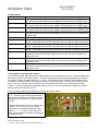
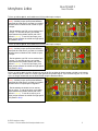
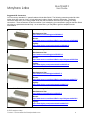
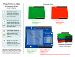
Mayhew Labs
Mux Shield II
User Guide
Table Of Contents:
Introduction
1
Hardware Description
1
Pin Descriptions
2
Freeing up Pins by Using Solder Jumpers
2
Suggested I/O Connectors
4
MuxShield Library for Arduino
5
_________________________________________
Introduction
Sometimes you need extra inputs and outputs on your Arduino; maybe you’re taking readings from dozens of
sensors or controlling a bunch of LEDs. Whatever it is, the Mux Shield will help you out. Stack it onto your Arduino
and you’ve just added 48 extra I/O pins. You can select whether the pins are analog inputs, digital inputs, or digital
outputs. The Mux Shield uses a clever combination of multiplexers, shift registers, and control signals to
accomplish this but don’t worry - it’s all wrapped up in a simple-to-use library that comes with examples.
This guide will help you get up and running and also explain how the shield works. If you want to skip the details
and get down to business, install the library and run the demo examples (see the MuxShield Library for Arduino
section).
_________________________________________
Hardware Description
The Mux Shield is an input and output (I/O) expander for Arduino platforms. It contains 48 connections for
increasing the number of analog inputs, digital inputs, and digital outputs. These 48 connections are split up into
three 16-pin rows: I/O1, I/O2, and I/O3. Each of these rows may be independently set as analog inputs, digital
inputs, or digital outputs in firmware or by using solder jumpers. That means you could have 16 analog inputs, 16
digital inputs, and 16 digital outputs simultaneously, or 32 digital outputs and 16 analog inputs simultaneously, or 48
digital outputs simultaneously, etc. Each 16-pin row cannot have split functionality - i.e. having 3 analog inputs and
13 digital outputs on row I/O1 is not possible. The Mux Shield uses Arduino digital pins 2, 4, 6, 7, analog input pins
A0, A1, A2, and optionally uses digital pins 8, 10, 11, 12.
The Mux Shield uses TI 74HC4067 analog multiplexers (mux’s) for input functionality and TI 74HC595 shift
registers for output functionality. Control lines are used in different ways depending on whether the I/O row is to be
an input or an output. If the I/O row is set as an input, the control lines are used as address lines to the mux’s. If
the row is an output, the control lines are used as clock and latch lines to the shift registers. See the Pin
Descriptions section for more details on how these lines are used.
© 2013 Mayhew Labs
Contact: [email protected]
1
Mayhew Labs
Pin Descriptions
Name
Pin
S0
2
S1
4
S2
6
S3
7
OUT MODE
IOS1
8
10
IOS2
11
IOS3
12
I/O1
A0
I/O2
A1
I/O3
A2
Mux Shield II
User Guide
Description
Select 0: Acts as address input S0 for multiplexers IC7, IC8, IC11 when OUT MODE is
low; acts as serial clock SCLK for shift registers IC3 and IC4 when OUT MODE is high
Select 1: Acts as address input S1 for multiplexers IC7, IC8, IC11 when OUT MODE is
low; acts as serial clock SCLK for shift registers IC5 and IC6 when OUT MODE is high
Select 2: Acts as address input S2 for multiplexers IC7, IC8, IC11 when OUT MODE is
low; acts as serial clock SCLK for shift registers IC9 and IC10 when OUT MODE is high
Select 3: Acts as address input S2 for multiplexers IC7, IC8, IC11 when OUT MODE is
low; acts as latch clock LCLK for shift registers IC3, IC4, IC5, IC6, IC9, IC10 when OUT
MODE is high
Pulled high to communicate with shift registers, pulled low to communicate with mux’s
In/Out Select 1: Pulled low when row I/O1 connections are to be used as inputs to
Arduino; pulled high when row I/O1 connections are to be used as outputs from Arduino
In/Out Select 2: Pulled low when row I/O2 connections are to be used as inputs to
Arduino; pulled high when row I/O2 connections are to be used as outputs from Arduino
In/Out Select 3: Pulled low when row I/O3 connections are to be used as inputs to
Arduino; pulled high when row I/O3 connections are to be used as outputs from Arduino
In/Out 1: Common input or output signal for row I/O1; used as a serial output to shift
registers IC3 and IC4 when IOS1 is high; used as common input from multiplexer IC7
when IOS1 is low
In/Out 2: Common input or output signal for row I/O2; used as a serial output to shift
registers IC5 and IC6 when IOS2 is high; used as common input from multiplexer IC8
when IOS1 is low
In/Out 3: Common input or output signal for row I/O3; used as a serial output to shift
registers IC9 and IC10 when IOS3 is high; used as common input from multiplexer IC11
when IOS1 is low
Freeing up Pins by Using Solder Jumpers
If you’re thinking, “Man, this shield uses too many Arduino pins!” then this section is for you. On the backside of the
Mux Shield, you’ll find some solder jumpers. These can be used to sever the connection between the shield and
your Arduino, freeing up Arduino pins 8, 10, 11, and 12. Here’s the basic idea behind the solder jumpers: One of
the features of the Mux Shield is its flexibility to be used for inputs and outputs – and this can be controlled in your
code. If you don’t need this control in software, you can ‘hardwire’ the I/O as input or output using the solder
jumpers. You can still change the configuration later on, but you’ll have to put new solder jumpers on the board.
See the instructions below for each pin:
To free up Arduino pin 10, and hardwire row I/O1 as either input or output:
1. Cut the trace between the pads of SJ2 (shown
in red). A solder jumper can be placed between
these pads at a later time if you want to re-enable
software control of whether I/O1 is used as input
or output.
2. Decide whether row I/O1 is to be used as input
or output. To use I/O1 as input, put a solder
jumper between the middle and left pad of SJ6
(shown in yellow). To use I/O1 as output, put a
solder jumper between the middle and right pad of
SJ6 (shown in blue).
© 2013 Mayhew Labs
Contact: [email protected]
2
Mayhew Labs
Mux Shield II
User Guide
To free up Arduino pin 11, and hardwire row I/O2 as either input or output:
1. Cut the trace between the pads of SJ3 (shown
in red). A solder jumper can be placed between
these pads at a later time if you want to re-enable
software control of whether I/O2 is used as input
or output.
2. Decide whether row I/O2 is to be used as input
or output. To use I/O2 as input, put a solder
jumper between the middle and left pad of SJ7
(shown in yellow). To use I/O2 as output, put a
solder jumper between the middle and right pad of
SJ7 (shown in blue).
To free up Arduino pin 12, and hardwire row I/O3 as either input or output:
1. Cut the trace between the pads of SJ4 (shown
in red). A solder jumper can be placed between
these pads at a later time if you want to re-enable
software control of whether I/O3 is used as input
or output.
2. Decide whether row I/O3 is to be used as input
or output. To use I/O3 as input, put a solder
jumper between the middle and left pad of SJ8
(shown in yellow). To use I/O3 as output, put a
solder jumper between the middle and right pad of
SJ8 (shown in blue).
To free up Arduino pin 8, the Mux Shield must use all 48 I/O’s as either all inputs (analog or digital) or all outputs.
This is because pin 8 is used as a control signal gate and chip enable signal. If pin 8 is freed up, pins 10, 11, and
12 are no longer needed and can be disconnected using the directions above.
1. Cut the trace between the pads of SJ1 (shown
in red). A solder jumper can be placed between
these pads at a later time if you want to re-enable
software control of input/output configuration.
2. Decide whether the shield is to be used as
input or output. To use all as input, put a solder
jumper between the middle and left pad of SJ5
(shown in yellow). To use all as output, put a
solder jumper between the middle and right pad of
SJ5 (shown in blue).
© 2013 Mayhew Labs
Contact: [email protected]
3
Mux Shield II
Mayhew Labs
User Guide
Suggested I/O Connectors
You can use any standard 0.1” spaced headers with the Mux Shield. The following connectors make life a little
easier since they come as 3-row x 16-pin packages in male or female, vertical or right angle. The female
connectors work well if you’re using jumper wires; the male connectors work well if you’re using wire wrap
connections. These connectors are also convenient if you’re designing your own board to plug into the Mux Shield
since they are polarized and mate firmly. As an extra bonus, you may able to get free samples from the
manufacturer.
Female, Right Angle
TE Connectivity 5650868-5
Manufacturer’s Site:
http://www.te.com/catalog/pn/en/5650868-5
Mouser:
http://www.mouser.com/Search/Refine.aspx?Keyword=5650868-5
DigiKey:
http://www.digikey.com/product-detail/en/5650868-5/
Female, Vertical
TE Connectivity 5535070-4
Manufacturer’s Site:
http://www.te.com/catalog/pn/en/5535070-4
Mouser:
http://www.mouser.com/Search/Refine.aspx?Keyword=5535070-4
DigiKey:
http://www.digikey.com/product-detail/en/5535070-4/
Male, Vertical
TE Connectivity 650477-5
Manufacturer’s Site:
http://www.te.com/catalog/pn/en/650477-5
Mouser:
http://www.mouser.com/Search/Refine.aspx?Keyword=650477-5
DigiKey:
http://www.digikey.com/product-detail/en/650477-5/
Male, Right Angle
TE Connectivity 650478-5
Manufacturer’s Site:
http://www.te.com/catalog/pn/en/650478-5
Mouser:
http://www.mouser.com/Search/Refine.aspx?Keyword=650478-5
DigiKey:
http://www.digikey.com/product-detail/en/650478-5/
© 2013 Mayhew Labs
Contact: [email protected]
4
Mayhew Labs
Mux Shield II
User Guide
MuxShield Library for Arduino
The MuxShield library is used to make controlling the Mux Shield hardware more straightforward than hardcoding
each control signal in every sketch. It wraps up all of the control logic into functions that make your code cleaner.
How to install the library:
1. Quit the Arduino application if it’s running
2. Download MuxShield.zip and unzip it.
3. Move the MuxShield folder to your Arduino libraries folder:
a. Windows: My Documents\Arduino\libraries
b. Mac: Documents/Arduino/libraries
c. Linux: the “libraries” folder in your sketchbook
4. Restart the Arduino application
How to Use the library:
1. Start the Arduino application
2. Begin with a demo:
a. File > Examples > MuxShield > Examples > (choose one of the following demos)
i. MuxShieldAnalogIn: an example of how to use the shield for 48 analog inputs
ii. MuxShieldComboIO: an example of how to use the shield for a combination of inputs
(analog and digital) and digital outputs
iii. MuxShieldDigitalIn: an example of how to use the shield for 48 digital inputs
iv. MuxShieldDigitalOut: an example of how to use the shield for 48 digital outputs
3. Add the MuxShield library to an existing sketch:
a. Sketch > Import Library > MuxShield
b. See the function reference below
Function Reference:
MuxShield()
Description: Use this to create an instance of the MuxShield library
Parameters: None
Return Value: None
MuxShield(int S0, int S1, int S2, int S3, int OUTMD,int IOS1, int IOS2, int IOS3,
int IO1, int IO2, int IO3)
Description: Create an instance of the MuxShield library with user-defined pins
Parameters: Arduino pin numbers that correspond to Mux Shield pins (see pin definitions section)
Return Value: None
void setMode(int io, int mode)
Description: Set the mode of a I/O row as analog in, digital in, or digital out
Parameters:
- io: 1, 2, or 3 corresponding to which row you want to set
- mode: DIGITAL_IN, DIGITAL_OUT, ANALOG_IN, or DIGITAL_IN_PULLUP (digital input with
internal pull up resistors enabled)
Return Value: None
© 2013 Mayhew Labs
Contact: [email protected]
5
Mayhew Labs
Mux Shield II
User Guide
void digitalWriteMS(int io, int chan, int val)
Description: Set the output state of one of the shield’s I/O pins
Parameters:
- io: 1, 2, or 3 corresponding to which row you want to set
- chan: 0 to 15 corresponding to which pin you want to set (for the row given)
- val: 0 or 1 (LOW or HIGH) corresponding to whether the pin should be logic GND or VCC
Return Value: None
int digitalReadMS(int io, int chan)
Description: Read the low/high state of one of the shield’s I/O pins
Parameters:
- io: 1, 2, or 3 corresponding to which row you want to get
- chan: 0 to 15 corresponding to which pin you want to get (for the row given)
Return Value: LOW or HIGH (integer 0 or 1)
int analogReadMS(int io, int chan)
Description: Read the analog value of one of the shield’s I/O pins
Parameters:
- io: 1, 2, or 3 corresponding to which row you want to get
- chan: 0 to 15 corresponding to which pin you want to get (for the row given)
Return Value: value of analog input (0 to 1023)
© 2013 Mayhew Labs
Contact: [email protected]
6