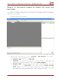
1
User’s Manual of Board Microcontroller “ET-EASY AVR LCD”
ET-EASY AVR LCD
ET-EASY AVR LCD is AVR Microcontroller Board that includes 16Character 2-Line Character LCD and Controller Circuit on board. The
board size is equal to LCD Display and there are 3 Connectors 10PIN
I/O. This Board uses AVR Microcontroller No.ATMEGA88 from ATMEL that
is contained in 28PIN DIP TYPE to be MCU on board. Its
characteristic feature is to be mini size Microcontroller but it is
full of the basic resources perfectly that is suitable to apply to
many projects easily. MCU internal board runs by the frequency
19.6608MHz; moreover, there are full of basic devices that are
necessary to use such as 512Byte E2PROM to store data and 1K Byte
SRAM. Furthermore, their Peripherals are suitable to apply for
controlling and processing data well because there is Hardware
System of SPI, UART, I2C, Watchdog, Timer/Counter, PWM and ADC.
It designs the structure of board as mini size because it is
easier to apply and develop program. The board is suitable to apply
for work that needs to use LCD Display; moreover, it is able to
transmit/receive data with the external device through RS232 Serial
Port Communication instantly. For the I/O, it is connected through
Connector 10PIN IDE; it is able to connect signal through Pair Cable
or it can connect with external I/O Board easily.
ETT CO., LTD
-1-
WWW.ETT.CO.TH
User’s Manual of Board Microcontroller “ET-EASY AVR LCD”
Specifications of Board
Use AVR MCU No.ATMEGA88 from ATMEL to be MCU on board and use
19.6608MHz Crystal Oscillator to be Clock Generator; so, it is
able to use with RS232 Serial Port Communication perfectly.
Can change and install other numbers of 28PIN AVR MCU in the
same serial such as ATMEGA8, ATMEGA48, ATMEGA168 and ATMEGA328.
Pin positions of these MCUs are compatible and are able to
install with board instantly without any circuit’s modification.
Has 8 KByte Flash/ 512 Byte EEPROM/ 1024 Byte SRAM
Has 3 of 20BIT I/O Port (PB(6BIT), PC(6BIT), PD(8BIT))
1 UART Serial Port Communication
1 SPI Port Communication
1 I2C Port Communication
1 of 16BIT Timer/Counter and 2 of 8BIT Timer/Counter
6-Channel 10BIT ADC
Has Connector I/O TTL with 3 of Header 2x5 (PB, PC and PD)
Has Switch RESET with circuit External Reset that is RC Reset
internal board
Board has already installed Program BootLoader into MCU; so,
user can develop program of board by Arduino or Program HEX File
into board through Program BootLoader instantly by only adding 1
more Switch BootLoader (Push Button Switch).
Has Connector RS232 that is CPA-4PIN according to the standard
of ETT for receiving-transmitting general data or programming
data into Board through BootLoader.
Has circuit to connect with LCD through IC 74HC595 and use
signal Pin PD4, PD47 and PB0 to control and command LCD.
Moreover, there is circuit to adjust the brightness of display
and circuit to control the Back Light. So, it saves amount of
I/O to connect with LCD and there is more remainder of I/O to
use for other application.
Use +5VDC Power Supply through Connector 2PIN CPA
Mini PCB Size: 8cm. x 3.7cm.
ETT CO., LTD
-2-
WWW.ETT.CO.TH
User’s Manual of Board Microcontroller “ET-EASY AVR LCD”
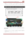
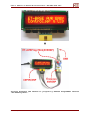
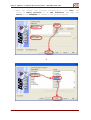
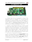
Structure of Board ET-EASY AVR LCD
9
1
2
8
3
4
7
5
Picture displays the structure of Board ET-EASY AVR LCD.
No.1: It is Resistor to adjust the brightness of LCD Display.
No.2: It is Connector Power Supply of board that uses +5VDC
Power Supply.
No.3: It is Switch RESET to reset operation of MCU.
No.4: It is Connector of signal from PC[0..5]; if developing
program by Arduino, it is signal pin of Analog[0..5].
ETT CO., LTD
-3-
WWW.ETT.CO.TH
User’s Manual of Board Microcontroller “ET-EASY AVR LCD”
No.5: It is Connector of signal from PB[0..5]; if developing
program by Arduino, it is signal pin of Digital[8..13].
No.6: It is Connector of signal from PD[0..7]; if developing
program by Arduino, it is signal pin of Digital[0..7].
No.7: It is LED to display status of signal Pin PB[5] or
Digital[13] of Arduino; this LED is driven through Transistor
BC337 as show in the circuit below.
VCC
D13
560
ETT CO., LTD
1K
-4-
BC337
Digital-13
PB5
WWW.ETT.CO.TH
User’s Manual of Board Microcontroller “ET-EASY AVR LCD”
No.8: It is Connector RS232 for general application and Upload
Code into MCU through BootLoader System. Its Pin arrangement
is displayed as below.
RXD
TXD
GND
1
6
2
7
3
8
4
9
5
RS232(PC)
1
2
3
4
CD
DSR
RXD
RTS
TXD
CTS
DTR
RI
GND
DB9(Female)
Figure displays the circuit of Cable RS232 for using with Board.
ETT CO., LTD
-5-
WWW.ETT.CO.TH
User’s Manual of Board Microcontroller “ET-EASY AVR LCD”
No.9: It is Connector of LCD 16-Character 2-Line that is
arranged in the single row from 14PIN to 16PIN. There is
signal pin is above the display as shown in the example below.
1
2
3
4
5
6
7
8
9 10 11 12 13 14 15 16
+5V GND VO RS RW EN D0 D1 D2 D3 D4 D4 D6 D7 A
K
Picture shows the feature of LCD that is installed with Board ETEASY AVR LCD.
No.10: It is MCU on board that is compatible with many numbers
of 28PIN AVR such as ATMEGA8, ATMEGA48, ATMEGA88, ATMEGA168
and ATMEGA328.
No.11: It is 19.6608MHz Crystal Oscillator.
ETT CO., LTD
-6-
WWW.ETT.CO.TH
User’s Manual of Board Microcontroller “ET-EASY AVR LCD”
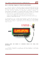
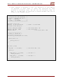
How to Develop Program of Board by BootLoader
If user wants to develop Program of Board ET-EASY AVR LCD by
BootLoader, it needs to interface Push Button Switch between PD2 and
GND to reset MCU to run in BootLoader. Normally, ETT has already
provided Program BootLoader with MCU that is installed with board;
so, user can test operation of BootLoader instantly. However, if
using AVRISP Programmer to program other data instead of Program
BootLoader, user needs to program new BootLoader first. The method
to test operation of Program BootLoader is described below;
- First of all, press and hold Switch PD2 for a while,
- Press Switch RESET while pressing and holding Switch PD2
- Remove Switch RESET but still pressing and holding Switch PD2
- Finally, remove Switch PD2.
If everything is ok, it makes LED blinking 3 times and then ON; it
means that MCU has already been entered and run in BootLoader
successfully. However, if pressing Switch RESET as normal without
pressing Switch PD2, it makes MCU will run according to the written
Code as usual.
Picture shows
BootLoader.
the
method
to
interface
Switch
for
using
with
Program BootLoader is able to develop program of board by
Arduino and is able to program HEX File from external into board
through RS232.
ETT CO., LTD
-7-
WWW.ETT.CO.TH
User’s Manual of Board Microcontroller “ET-EASY AVR LCD”
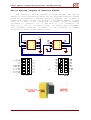
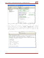
How to Develop Program of Board by AVRISP
The method to develop program of Board ET-EASY AVR LCD by
AVRISP is restricted because Board has not provided Connector inside
board for programming by “AVRISP” directly; however, user is able to
modify and connect signal pin of AVR to program by AVRISP. In this
case, it is able to use “10PIN/ISP” to convert signal of AVRISP
according to Connector I/O of AVR PB[0..5]; so, Connector I/O
PB[0..5] or D[8..13] of board is able to connect with Programmer
that arranges connector according to the standard of AVRISP
instantly as shown in the example below.
VCC
MOSI
RES#
SCK
MISO
1
3
5
7
9
PB0
PB2
PB4
2
4
6
8
10
VCC
AVRISP
1
3
5
7
9
2
4
6
8
10
PB1
PB3
PB5
RESET#
Digital[8..13]
ETT CO., LTD
-8-
WWW.ETT.CO.TH
User’s Manual of Board Microcontroller “ET-EASY AVR LCD”
ETT CO., LTD
-9-
WWW.ETT.CO.TH
User’s Manual of Board Microcontroller “ET-EASY AVR LCD”
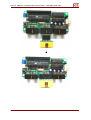
Picture displays the method to program by AVRISP Programmer version
“ET-AVRProg Mini”.
ETT CO., LTD
-10-
WWW.ETT.CO.TH
User’s Manual of Board Microcontroller “ET-EASY AVR LCD”
How to program BootLoader into Board ET-EASY AVR LCD
Normally, Board ET-EASY AVR LCD has already been programmed
BootLoader, so user can use it instantly. However, if user wants to
change BootLoader to the new one; or the mistake occurs and it makes
BootLoader damaged, user can re-program BootLoader into Board. This
Board ET-EASY AVR LCD is designed to have Connector AVRISP to
program Code into MCU directly, so it is compatible with every
Programmer version that has the Connector according to the standard
AVRISP of ATMEL. In this case, we will describe the method to program
BootLoader by ETT Programmer version “ET-AVR ISP USB V1.0” and
Program “AVR Studio 4” of ATMEL to be operator as described below.
1. Interface RS232 Cable from computer into Board ET-EASY AVR LCD
and then supply power into board.
2. Interface USB Cable with Programmer ET-AVR ISP USB V1 and
connect 10PIN Pair Cable between Connector AVRISP of both
Boards.
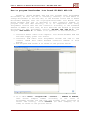
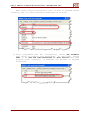
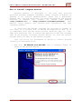
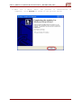
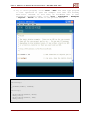
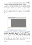
3. Run Program AVR Studio 4 as shown in the picture below.
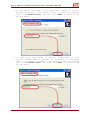
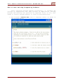
4. Go to Menu Tools → Program AVR → Connect.. → STK500 or AVRISP,
then choose Comport number according to the value of
Programmer ET-AVR ISP USB that has already been installed in
Driver and finally, click Connect (in this example, it is
Com9) as shown in the picture below.
ETT CO., LTD
-11-
WWW.ETT.CO.TH
User’s Manual of Board Microcontroller “ET-EASY AVR LCD”
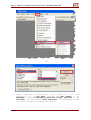
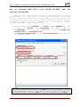
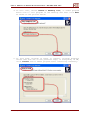
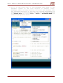
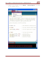
5. After
connected
successfully,
user
needs
to
test
the
connection. go to Tab Main, choose the MCU number to be
ATmega88; choose Programming Mode and target Settings to be
ISP Mode; and then choose Read Signature. If everything is OK,
its result should be displayed as below.
ETT CO., LTD
-12-
WWW.ETT.CO.TH
User’s Manual of Board Microcontroller “ET-EASY AVR LCD”
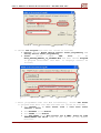
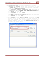
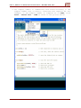
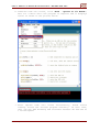
6. Choose Tab Program and then set values as follows;
Device: Choose Erase device before flash programming and
Verify device after programming.
Flash:
Choose
Input
HEX
File
to
be
BOOT_EASY88_MANUAL_19_6608MHZ.HEX and then choose Program
to program BootLoader into MCU. It displays results as
follows;
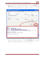
7. After programmed Code into MCU successfully, choose Tab Fuses
to program Fuse Bite into MCU and then set values as follows;
Set BOOTSZ to be Boot Flash size = 1024 word start
address = $0C00
Set BOOTRST to be Enable
Set SPIEN to be Enable
Set SUT_CKSEL to be Ext.Crystal Osc 8.0MHz; Start-up time
PWRDN/RESET:16K CK/14 that is the choice at the lowest
position.
ETT CO., LTD
-13-
WWW.ETT.CO.TH
User’s Manual of Board Microcontroller “ET-EASY AVR LCD”
When chose values successfully, user is able to program values
instantly and its result should be displayed as follows;
8. After programmed Fuse Bit successfully, choose Tab LockBits
and choose to protect only BootLoader. In this case, choose
BLB1 to be LPM and SPM prohibited in Boot Section and then
program value instantly, it finishes the process of Program
BootLoader.
ETT CO., LTD
-14-
WWW.ETT.CO.TH
User’s Manual of Board Microcontroller “ET-EASY AVR LCD”
How to Program HEX
through BootLoader
File
into
Board
ET-EASY
AVR
LCD
Now, we will describe the method to develop program of Board
ET-EASY AVR LCD in the format of AVR Microcontroller; after wrote
program, compiled program and then got HEX File successfully, user
can program the HEX Code of this program through Program BootLoader
of Board. In this case, we recommend user to use Program AVRDude
through AVRDudeGUI as described below;
1. Build Folder name “AVRDUDE” in Drive C (“C:\AVRDUDE\”), copy
Program of avrdude and avrdudeGUI and paste them in
“C:\AVRDUDE\”. In this case, there are 3 files; avrdude.exe,
avrdude.conf and avrdudegui.exe.
2. Run Program AVRDude.EXE, choose Tab Configuration and then set
values as follows.
NOTE: If the Comport number is greater than COM8, user needs to type
the Comport number in the blank of –P Port by self. For example, if the
Comport number has 2 digits, user needs to add sign “\\.\” in front of
the Comport number; if it is Com13, it must be written as “\\.\com13”.
ETT CO., LTD
-15-
WWW.ETT.CO.TH
User’s Manual of Board Microcontroller “ET-EASY AVR LCD”
Set Configuration value into Program AVRDudeGUI as follows;
Location of avrdude: Choose name and location of file
“avrdude.exe” that has already been installed in the step 1
that is “C:\AVRDude\avrdude.exe”.
-C Location of alternate configuration file: Choose name and
location of file “avrdude.conf” that has already been
installed in the step 1 that is “C:\AVRDude\avrdude.conf”.
-p Device: Set it as m88.
-c Programmer: Set it as stk500.
-p Port: Choose Comport number according to the value that
is exactly connected with computer PC.
-b Baudrate: Set it as 19200.
3. Go to Tab File, choose Write and Verify in the part of Flash
and then specify the HEX File name to program as required. In
this case, the HEX File in this example is written by C
Language of WinAVR that is in “C:\AVRDude\base88_led.hex” in
as shown in the picture below.
ETT CO., LTD
-16-
WWW.ETT.CO.TH
User’s Manual of Board Microcontroller “ET-EASY AVR LCD”
4. When set values into program successfully, choose Execute in
Tab Files and it makes Program avrdude start programming HEX
File into board instantly. User needs to wait for a while
until it is complete as shown in the picture below.
5. After programmed successfully. Press Switch RESET and it makes
board start running instantly. In this case, we can see LED
blinking alternate between ON and OFF continuously.
ETT CO., LTD
-17-
WWW.ETT.CO.TH
User’s Manual of Board Microcontroller “ET-EASY AVR LCD”
How to Develop Program of ET-EASY AVR LCD by Arduino
Normally, Board ET-EASY AVR LCD has already installed Program
BootLoader;
in
this
case,
it
is
BootLoader
called
“BOOT_EASY88_MANUAL_19_6608MHZ.HEX”. It is the BootLoader that is
the original of Arduino and is edited and improved by ETT,
especially in the part of conditional operations according to the
Hardware System of Board ET-EASY AVR LCD. This Program BootLoader is
used to Upload Code from computer PC to MCU on board without using
any external Programmer. The additional specifications of BootLoader
that is edited and improved by ETT are described below.
- Communicate with external Program by Protocol STK500
(STK500V1)
- Use 19200 Baudrate at 19.6608MHz XTAL
- 2KByte Program BootLoader runs at position 0x1800 - 0x1FFF
- Use LED that is connected at Pin Digital-13(PB5) to display
the status while BootLoader is running.
- Program in BootLoader always runs automatically after
resetting, MCU always starts running in this BootLoader first.
Then, it checks Logic status of Pin PD2; it status of Pin PD2
is HIGH, it exits from BootLoader and starts following the
user’s command automatically; on the other hand, if status of
Pin PD2 is LOW, it starts running in BootLoader Programming
Mode. While BootLoader Programming Mode is running, user will
see LED that is connected at Pin Digital-13(PB5) blinking 3
times and then ON because it waits for the communication from
the program to Upload Code into MCU until it is reset.
Board ET-EASY AVR LCD uses Switch BL(PD2) and Switch RESET to
choose the operation of BootLoader. If user sets MCU to run by the
written Code, it needs to press Switch RESET only; on the other
hand, if user sets MCU to run in BootLoader Programming Mode, user
needs to follows these instructions;
- Press and hold Switch BL(PD2) for a while,
- Press Switch RESET while pressing and holding Switch BL(PD2),
- Remove Switch RESET but still pressing and holding Switch
BL(PD2),
- Finally, remove Switch BL(PD2).
We can see the LED that is connected at Pin PB5 blinking 3 times and
then ON, it means that MCU has already run in BootLoader
successfully.
ETT CO., LTD
-18-
WWW.ETT.CO.TH
User’s Manual of Board Microcontroller “ET-EASY AVR LCD”
How to Install Program Arduino
Program Arduino is developed to use with many Platform
Operating Systems; nowadays (December, 2008), Program of Arduino is
updated to be version “Arduino-0012”. There are 4 Platforms;
Windows, Mac, OSx and Linux. User can check and download new program
versions
of
Arduino
free
without
any
charge
from
website
“http://arduino.cc/” or “http://arduino.cc/en/Main/Software”. This
website always updates and contains more information and news
regarding Arduino.
If using with ETT Boards, programs are provided in CD-ROM; in
this case, it is program that is edited and improved by ETT, so it
is compatible with new ETT Board version. Moreover, ETT Co., Ltd.
adds more Libraries that is edited and improved by ETT and includes
them in the program, including Install Shield. So, user can install
program easily as same as the general program.
User can follow the procedures of Wizard to install program
instantly as described below;
1. Run File “ET-ARDUINO-0012-WIN.EXE” and it displays result as
shown in the picture below;
ETT CO., LTD
-19-
WWW.ETT.CO.TH
User’s Manual of Board Microcontroller “ET-EASY AVR LCD”
2. In this
program
that is
picture
step, user needs to set position of folder to install
according to the Default value of installing program
“C:\Arduino-0012” and then click Next as shown in the
below.
3. In this step, user needs to specify Folder name to call
program through Menu of Windows. In this case, we recommend
user to set value according to the Default values of program
that is “C:\Arduino-0012” and then click Next as shown in the
picture below.
ETT CO., LTD
-20-
WWW.ETT.CO.TH
User’s Manual of Board Microcontroller “ET-EASY AVR LCD”
4. In this case, choose Create a desktop icon, it makes program
build Icon to call program on the Desktop and then click Next
as shown in the picture below.
5. In this step, program is ready to install. Program displays
values that are set in the previous step; if everything is OK,
click Install and it makes program start installing instantly.
ETT CO., LTD
-21-
WWW.ETT.CO.TH
User’s Manual of Board Microcontroller “ET-EASY AVR LCD”
6. Wait for a while until the process of installation
complete, click Finish as shown in the picture below.
ETT CO., LTD
-22-
is
WWW.ETT.CO.TH
User’s Manual of Board Microcontroller “ET-EASY AVR LCD”
How to test writing Program by Arduino
After installed Program Arduino successfully, it finishes the
process of preparation; the next process is application, writing
program and learning the operation as required. First of all, user
needs to install Program Arduino to learn as described below.
1. Run Program “arduino.exe” and it displays result as shown in
the picture below.
ETT CO., LTD
-23-
WWW.ETT.CO.TH
User’s Manual of Board Microcontroller “ET-EASY AVR LCD”
2. If it is the first time to call program, user needs to set
Hardware System to use with Program of Arduino first.
Nowadays, there are many versions of circuit and Hardware that
are designed and built to use with the Program Development of
Arduino. If it is Board ET-EASY AVR LCD, set the name of Board
as “EASY88 BASE” by click “Tools → Board → “ET-EASY88 BASE” as
shown in the picture below.
ETT CO., LTD
-24-
WWW.ETT.CO.TH
User’s Manual of Board Microcontroller “ET-EASY AVR LCD”
3. Set Comport number to communicate with board according to the
Comport number that is exactly connected with computer PC. For
example, if the Comport number of computer PC is COM5, click
Tools → Serial Port → COM5 as shown in the picture below.
ETT CO., LTD
-25-
WWW.ETT.CO.TH
User’s Manual of Board Microcontroller “ET-EASY AVR LCD”
4. Try to write program, click “File → New” and then type program
to test operation or open the example file that has already
been built instead. In this case, we recommend user to test
program by blinking light, click “File → sketchbook → Examples
→ Digital → Blink” as shown in the picture below.
int ledPin = 13;
void setup()
{
pinMode(ledPin, OUTPUT);
}
void loop()
{
digitalWrite(ledPin, HIGH);
delay(1000);
digitalWrite(ledPin, LOW);
delay(1000);
}
ETT CO., LTD
-26-
WWW.ETT.CO.TH
User’s Manual of Board Microcontroller “ET-EASY AVR LCD”
5. Compile the program, click “Sketch → Verify/Compile” as shown
in the example below.
ETT CO., LTD
-27-
WWW.ETT.CO.TH
User’s Manual of Board Microcontroller “ET-EASY AVR LCD”
6. Download Code into board, click “File → Upload to I/O Board”;
wait for a while until the program is complete and it displays
result as shown in the picture below.
7. After Upload Code into board successfully, board starts
running follow the written program instantly. In this case,
user can see LED blinking and alternate between ON and OFF at
1 second speed.
ETT CO., LTD
-28-
WWW.ETT.CO.TH
User’s Manual of Board Microcontroller “ET-EASY AVR LCD”
How to develop program of ET-EASY AVR LCD as AVR
Microcontroller
If user wants to develop program into Board ET-EASY AVR LCD as
usual in the format of AVR Microcontroller, user can choose the
required language to write program by self. In this case, user can
choose any language that supports the application of AVR MCU
No.ATmega88; moreover, user can manage all resources internal
ATmega88 by self. There are 2 methods as described below;
Using External Programmer to develop program: It is good
because user dose not loss any resource, so user can use and
set specification of resources in MCU as required. However,
user has to use the external Programmer to program code into
MCU. In this case, user can use any programmer version that
supports the application of MCU No.ATmega88 and it has
Connector according to the standard of AVRISP of ATMEL.
Using BootLoader to develop program: It is good because user
can program code into MCU through Program BootLoader instantly
without using any external programmer after wrote program
successfully. However, it needs to loss 2 KByte Flash Memory
that is used to store Code Program (0x1800 – 0x1FFF) to
install Program BootLoader; normally, Board ET-EASY AVR LCD
has already been installed Program BootLoader. In this case,
there are totally 6 KByte from 8KByte that user is able to
write program, user needs to write Code Program in the
specific address between 0x0000 to 0x17FF (0x0C00 – 0x0FFF K
Word). For SRAM, EEPROM and other resources internal MCU, user
can use them completely.
ETT CO., LTD
-29-
WWW.ETT.CO.TH
User’s Manual of Board Microcontroller “ET-EASY AVR LCD”
Example of Developing Program by WinAVR and using with
BootLoader
This example shows how to develop program into ATmega88 with C
Language by using Program AVR Studio4 of ATMEL and C Language
Compiler of WinAVR.
1. Run Program AVR Studio4.
2. Build the new project, click “project → New project” and then
set values into program as follows;
Project type: Set it as AVR GCC.
Location: It stores the project, user needs to specify the
required location of Folder to store File and Code of
project; in this example, it is “C:\test_easy88\”.
Project name: Specify the project name as required; in this
example, it is “led_blink” and then choose Create initial
file. When we have already specified the project name
successfully, the program will build the file name that has
the same as the user's project name automatically.
ETT CO., LTD
-30-
WWW.ETT.CO.TH
User’s Manual of Board Microcontroller “ET-EASY AVR LCD”
3. When set values into program successfully; click Next; set
value in Debug platform to be AVR Simulator and then set
Device to be ATmega88 as shown in the picture below.
ETT CO., LTD
-31-
WWW.ETT.CO.TH
User’s Manual of Board Microcontroller “ET-EASY AVR LCD”
4. Type command of program to test its operation in Text Editor
of program; in this case, it tests the operation by Code
program of blinking light. We can see the blinking light at
PB5, it is LED that is installed on Board ET-EASY AVR LCD as
shown in the example below.
/******************************/
/* Program Test LED Blinking */
/* Board : ET-EASY AVR LCD */
/* MCU
: ATmega88
*/
/* X-TAL : 19.6608MHz
*/
/******************************/
#include <avr/io.h>
#define F_CPU 19660800UL
#include <util/delay.h>
// X-TAL = 19.6608 MHz
#define PORT_LED PORTB
#define DIR_LED DDRB
#define LED 5
// Port Drive LED = PB
// Port Direction
// Pin Drive LED = PB5
/********************/
/* Delay 1..65535 mS */
/********************/
void delay_ms(unsigned int time)
{
while(time-->0)
{
_delay_ms(1.0);
}
}
int main (void)
{
DIR_LED |= (1<<LED);
while(1)
{
PORT_LED &= ~(1<<LED);
delay_ms(200);
PORT_LED |= (1<<LED);
delay_ms(200);
// Pin Drive LED = Out
// Pin LED = 0
// Pin LED = 1
}
}
ETT CO., LTD
-32-
WWW.ETT.CO.TH
User’s Manual of Board Microcontroller “ET-EASY AVR LCD”
5. After typed Code Program successfully, user can
program instantly; go to Menu “build → rebuild all”.
case, the code that is compiled will be HEX File that
name as same as the project that is built as shown
picture below;
ETT CO., LTD
-33-
compile
In this
has the
in the
WWW.ETT.CO.TH