1
User’s
Manual
EJX210B
Flange Mounted Differential
Pressure Transmitter
IM 01C27C01-01EN
IM 01C27C01-01EN
Yokogawa Electric Corporation
8th Edition
i
EJX210B
Flange Mounted Differential Pressure Transmitter
IM 01C27C01-01EN 8th Edition
Contents
1.
2.
Introduction................................................................................................ 1-1
1.1
Safe Use of This Product ................................................................................. 1-2
1.2
Radio Wave......................................................................................................... 1-3
1.3
Warranty.............................................................................................................. 1-3
1.4
Trademarks......................................................................................................... 1-3
1.5
ATEX Documentation........................................................................................ 1-4
Handling Cautions..................................................................................... 2-1
2.1
Model and Specifications Check...................................................................... 2-1
2.2
Unpacking........................................................................................................... 2-1
2.3
Storage................................................................................................................ 2-1
2.4
Selecting the Installation Location ................................................................. 2-2
2.5
Pressure Connection......................................................................................... 2-2
2.6
Restrictions on Use of Radio Transceivers.................................................... 2-3
2.7
Insulation Resistance and Dielectric Strength Test....................................... 2-3
2.8
Installation of an Explosion-Protected Instrument........................................ 2-4
2.8.1
FM Approval........................................................................................ 2-4
2.8.2
CSA Certification................................................................................. 2-5
2.8.3
ATEX Certification............................................................................... 2-5
2.8.4
IECEx Certification.............................................................................. 2-7
2.9
EMC Conformity Standards.............................................................................. 2-7
2.10
Pressure Equipment Directive (PED).............................................................. 2-7
2.11
Low Voltage Directive........................................................................................ 2-8
2.12
Regulatory Compliance for Radio and Telecommunication......................... 2-8
2.12.1
Radio and Telecommunications Terminal Equipment Directive (R&TTE)
..................................................................................................... 2-8
2.12.2
FCC compliance................................................................................. 2-8
2.12.3
Industry Canada (IC) compliance....................................................... 2-9
3.
Component Names................................................................................... 3-1
4.
Installation.................................................................................................. 4-1
4.1
Precautions ....................................................................................................... 4-1
4.2
Mounting ............................................................................................................ 4-1
4.3
Rotating Transmitter Section............................................................................ 4-1
4.4
Changing the Direction of Integral Indicator ................................................. 4-2
4.5
Changing the direction of the antenna............................................................ 4-2
8th Edition: Jan. 2014 (YK)
All Rights Reserved, Copyright © 2010, Yokogawa Electric Corporation
IM 01C27C01-01EN
ii
4.6
4.7
5.
5.2
6.2
8.
Mounting to Pressure Detector Section.............................................. 4-3
4.6.2
Mounting to Process Flange............................................................... 4-3
Affixing the Teflon Film..................................................................................... 4-4
Impulse Piping Installation Precautions......................................................... 5-1
5.1.1
Connecting Impulse Piping to the Transmitter.................................... 5-1
5.1.2
Routing the Impulse Piping................................................................. 5-1
Impulse Piping Connection Examples............................................................ 5-2
Wiring.......................................................................................................... 6-1
6.1
7.
4.6.1
Installing Impulse Piping.......................................................................... 5-1
5.1
6.
Mounting the Flushing Connection Ring........................................................ 4-3
Mounting Antenna and Wiring.......................................................................... 6-1
6.1.1
Mounting the antenna......................................................................... 6-1
6.1.2
Mounting External Antenna and Wiring Antenna Extension Cable.... 6-2
6.1.2.1
Mounting of External Antenna............................................................. 6-2
6.1.2.2
Wiring of Antenna Extension Cable.................................................... 6-2
6.1.2.3
Mounting of Arrester and Wiring......................................................... 6-4
Grounding........................................................................................................... 6-4
Operation.................................................................................................... 7-1
7.1
Preparation for Starting Operation.................................................................. 7-1
7.2
Zero Point Adjustment...................................................................................... 7-2
7.3
Starting Operation............................................................................................. 7-3
7.4
Connecting to the Field Wireless Network...................................................... 7-3
7.5
Shutting Down The Transmitter....................................................................... 7-5
7.6
Venting or Draining Transmitter Pressure-detector Section........................ 7-5
7.6.1
Draining Condensate (low pressure side).......................................... 7-5
7.6.2
Venting Gas (low pressure side)......................................................... 7-6
7.6.3
Draining Condensate for Flushing Connection Ring.......................... 7-6
7.6.4
Venting Gas for Flushing Connection Ring......................................... 7-7
Setting Parameters.................................................................................... 8-1
8.1
Environment for parameter setting.................................................................. 8-1
8.2
Preparing Software............................................................................................ 8-1
8.3
8.2.1
Softwares for the Field Wireless Configuration Tool and the Device
Configuration Tool............................................................................... 8-1
8.2.2
Software Download............................................................................. 8-1
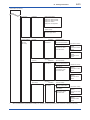
Setting Parameters............................................................................................ 8-2
8.3.1
Parameter Usage and Selection......................................................... 8-2
8.3.2
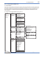
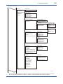
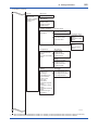
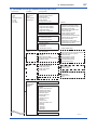
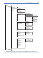
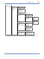
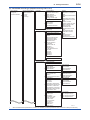
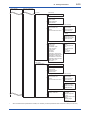
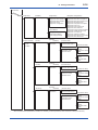
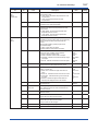
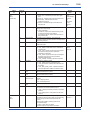
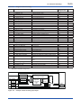
Function Block and Menu Tree........................................................... 8-3
8.3.3
Parameters for Wireless Communication......................................... 8-17
8.3.4
Tag and Device Information.............................................................. 8-18
8.3.5
Unit.................................................................................................... 8-18
8.3.6
Range Change.................................................................................. 8-18
8.3.7
Output Signal Low Cut Mode Setup................................................. 8-19
IM 01C27C01-01EN
iii
8.4
9.
8.3.8
Integral Indicator Setup..................................................................... 8-19
8.3.9
Unit for Displayed Temperature........................................................ 8-20
8.3.10
Unit for Displayed Static Pressure.................................................... 8-20
8.3.11
Zero Point Adjustment and Span Adjustment................................... 8-20
8.3.12
Software Write Protection................................................................. 8-23
8.3.13
Switching to Deep Sleep Mode......................................................... 8-23
8.3.14
Switching to Silence Mode................................................................ 8-23
Self-Diagnostics............................................................................................... 8-24
8.4.1
Identify Problems by Using the Device Configuration Tool............... 8-24
8.4.2
Alert Report....................................................................................... 8-25
8.4.3
Checking with Integral Indicator........................................................ 8-27
Maintenance............................................................................................... 9-1
9.1 Overview............................................................................................................. 9-1
9.2
Calibration Instruments Selection................................................................... 9-1
9.3
Calibration.......................................................................................................... 9-1
9.4
Disassembly and Reassembly......................................................................... 9-3
9.5
9.4.1
Replacing the Integral Indicator.......................................................... 9-3
9.4.2
Replacing the RF Assembly................................................................ 9-4
9.4.3
Replacing the CPU Assembly............................................................. 9-4
9.4.4
Replacing the Process Connector Gaskets........................................ 9-5
9.4.5
Replacing the Battery Pack................................................................ 9-5
9.4.6
Replacing the Batteries....................................................................... 9-5
9.4.7
Handling Batteries............................................................................... 9-6
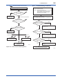
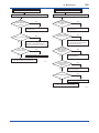
Troubleshooting................................................................................................. 9-7
9.5.1
Basic Troubleshooting........................................................................ 9-7
9.5.2
Troubleshooting Flowcharts................................................................ 9-8
9.5.3
Errors and Countermeasures........................................................... 9-10
10.
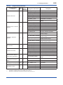
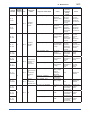
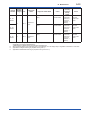
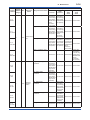
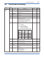
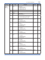
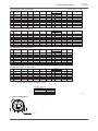
Parameter Summary............................................................................... 10-1
11.
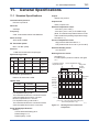
General Specifications........................................................................... 11-1
11.1
Standard Specifications.................................................................................. 11-1
11.2
Model and Suffix Codes.................................................................................. 11-4
11.3
Optional Specifications................................................................................. 11-10
11.4
Dimensions..................................................................................................... 11-12
Revision Information................................................................................................i
IM 01C27C01-01EN
1.
1-1
<1. Introduction>
Introduction
Thank you for purchasing the DPharp EJX
Differential Pressure transmitter.
• Yokogawa assumes no responsibilities for this
product except as stated in the warranty.
Your EJX Pressure Transmitter was precisely
calibrated at the factory before shipment. To ensure
both safety and efficiency, please read this manual
carefully before you operate the instrument.
• If the customer or any third party is harmed by
the use of this product, Yokogawa assumes
no responsibility for any such harm owing to
any defects in the product which were not
predictable, or for any indirect damages.
NOTE
This manual covers the EJX210B Flange
Mounted differential pressure transmitter
and describes how to use for not only the
integral antenna type transmitters but also the
detachable antenna ones.
Unless otherwise stated, the illustrations in
this manual are of the integral antenna type
transmitter. Users of the other models and
specifications should bear in mind that certain
features of their instrument will differ from those
shown in the illustrations of the EJX210B.
Regarding This Manual
• This manual should be provided to the end
user.
• The contents of this manual are subject to
change without prior notice.
• All rights reserved. No part of this manual may
be reproduced in any form without Yokogawa’s
written permission.
• Yokogawa makes no warranty of any kind with
regard to this manual, including, but not limited
to, implied warranty of merchantability and
fitness for a particular purpose.
• If any question arises or errors are found, or if
any information is missing from this manual,
please inform the nearest Yokogawa sales
office.
• The specifications covered by this manual are
limited to those for the standard type under the
specified model number break-down and do not
cover custom-made instruments.
• Please note that changes in the specifications,
construction, or component parts of the
instrument may not immediately be reflected
in this manual at the time of change, provided
that postponement of revisions will not cause
difficulty to the user from a functional or
performance standpoint.
• The following safety symbols are used in this
manual and on the product:
WARNING
Indicates a potentially hazardous situation which,
if not avoided, could result in death or serious
injury.
CAUTION
Indicates a potentially hazardous situation which,
if not avoided, may result in minor or moderate
injury or physical damage. It may also be used to
alert against unsafe practices.
IMPORTANT
Indicates that operating the hardware or software
in this manner may damage it or lead to system
failure.
NOTE
Draws attention to information essential for
understanding the operation and features.
Functional grounding terminal
Caution
This symbol indicates that the operator
must refer to an explanation in the user’s
manual in order to avoid the risk of injury
or death of personnel or damage to the
instrument.
IM 01C27C01-01EN
1.1 Safe Use of This Product
For the safety of the operator and to protect the
instrument and the system, please be sure to follow
this manual’s safety instructions when handling this
instrument. If these instructions are not heeded,
the protection provided by this instrument may be
impaired. In this case, Yokogawa cannot guarantee
that the instrument can be safely operated. Please
pay special attention to the following points:
(a) Installation
• This instrument may only be installed by an
engineer or technician who has an expert
knowledge of this device. Operators are not
allowed to carry out installation unless they
meet this condition.
• With high process temperatures, care must
be taken not to burn yourself by touching the
instrument or its casing.
• Never loosen the process connector nuts when
the instrument is installed in a process. This can
lead to a sudden, explosive release of process
fluids.
1-2
<1. Introduction>
(d) Explosion Protected Type Instrument
• Users of explosion proof instruments should
refer first to section 2.8 (Installation of an
Explosion Protected Instrument) of this manual.
• The use of this instrument is restricted to those
who have received appropriate training in the
device.
• Take care not to create sparks when accessing
the instrument or peripheral devices in a
hazardous location.
• Repair or modification to this instrument by
customer will cause malfunction of explosion
protect function and hazardous situation. If you
need to repair or modification, please contact
the nearest Yokogawa office.
(e) Modification
• Yokogawa will not be liable for malfunctions or
damage resulting from any modification made
to this instrument by the customer.
• When draining condensate from the pressure
detector section, take appropriate precautions
to prevent the inhalation of harmful vapors and
the contact of toxic process fluids with the skin
or eyes.
• When removing the instrument from a
hazardous process, avoid contact with the fluid
and the interior of the meter.
• All installation shall comply with local installation
requirements and the local electrical code.
(b) Wiring
• The instrument must be installed by an
engineer or technician who has an expert
knowledge of this instrument. Operators are not
permitted to carry out wiring unless they meet
this condition.
(c) Maintenance
• Please carry out only the maintenance
procedures described in this manual. If you
require further assistance, please contact the
nearest Yokogawa office.
• Care should be taken to prevent the build up of
dust or other materials on the display glass and
the name plate. To clean these surfaces, use a
soft, dry cloth.
IM 01C27C01-01EN
1.2 Radio Wave
IMPORTANT
-
-
-
This instrument is equipped with a wireless
module which is designated as a certification
of construction type as a wireless
facility for 2.4 GHz band low-power data
communication system of the Radio Act.
Refer to 2.12 “Regulatory Compliance for
Radio and Telecommunication” for detail.
Due to the designated certification of
construction type, users may be subject to
legal punishment in case of:
- Disassembling or modifying the wireless
module or antenna in this instrument
- Peeling off the certification label attached
to the wireless module in this instrument
Preventing interference with other wireless
stations
The operating frequency bandwidth of this
instrument may overlap the same range
as industrial devices, scientific devices,
medical devices, microwave ovens, licensed
premises radio stations and non-licensed
specified low-power radio stations for mobile
object identification systems used in factory
production lines.
Before using this instrument, ensure that
neither a premises radio station nor specified
low power radio station for mobile object
identification systems is in use nearby.
If this instrument causes radio wave
interference to a wireless station for mobile
object identification systems, promptly
change the frequency being used or turn
off the source of radio wave emissions.
Then, contact a Yokogawa office regarding
countermeasures to prevent interference,
such as setting up partitions.
1.3 Warranty
• The warranty shall cover the period noted on
the quotation presented to the purchaser at the
time of purchase. Problems occurring during
the warranty period shall basically be repaired
free of charge.
<1. Introduction>
1-3
• If any problems are experienced with this
instrument, the customer should contact the
Yokogawa representative from which this
instrument was purchased or the nearest
Yokogawa office.
• If a problem arises with this instrument,
please inform us of the nature of the problem
and the circumstances under which it
developed, including the model specification
and serial number. Any diagrams, data and
other information you can include in your
communication will also be helpful.
• The party responsible for the cost of fixing the
problem shall be determined by Yokogawa
following an investigation conducted by
Yokogawa.
• The purchaser shall bear the responsibility for
repair costs, even during the warranty period, if
the malfunction is due to:
- Improper and/or inadequate maintenance by
the purchaser.
- Malfunction or damage due to a failure
to handle, use, or store the instrument in
accordance with the design specifications.
- Use of the product in question in a location
not conforming to the standards specified by
Yokogawa, or due to improper maintenance
of the installation location.
- Failure or damage due to modification or
repair by any party except Yokogawa or an
approved representative of Yokogawa.
- Malfunction or damage from improper
relocation of the product in question after
delivery.
- Reason of force majeure such as fires,
earthquakes, storms/floods, thunder/
lightening, or other natural disasters, or
disturbances, riots, warfare, or radioactive
contamination.
1.4 Trademarks
In this document, trademarks or registered
trademarks are not marked with “™” or “®”.
Product names and company names in this
document are trademarks or registered trademarks
of the respective companies.
IM 01C27C01-01EN
<1. Introduction>
1-4
1.5 ATEX Documentation
This is only applicable to the countries in European Union.
GB
DK
SK
CZ
I
LT
E
LV
NL
EST
PL
SF
SLO
P
H
F
BG
D
RO
S
M
GR
IM 01C27C01-01EN
2.
2-1
<2. Handling Cautions>
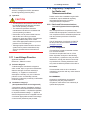
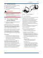
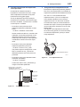
Handling Cautions
This chapter provides important information on how
to handle the transmitter. Read this carefully before
using the transmitter.
EJX Series transmitters are thoroughly tested at the
factory before shipment. When taking delivery of an
instrument, visually check them to make sure that
no damage occurred during shipment.
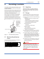
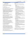
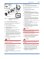
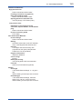
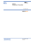
Also check that all transmitter mounting hardware
shown in figure 2.1 is included. If the transmitter
is ordered without the process connector, the
transmitter mounting hardware will not be included.
After checking the transmitter, carefully repack it in
its box and keep it there until you are ready to install
it.
Antenna
The antenna is a
detachable type
when Amplifier
housing code 8 is
selected, and no
antenna is
provided for
Amplifier
housing code 9.
Process connector
2.2 Unpacking
Keep the transmitter in its original packaging to
prevent it from being damaged during shipment.
Do not unpack the transmitter until it reaches the
installation site.
2.3 Storage
The following precautions must be observed when
storing the instrument, especially for a long period.
(a) Select a storage area which meets the following
conditions:
• It is not exposed to rain or subject to water
seepage/leaks.
• Vibration and shock are kept to a minimum.
• It has an ambient temperature and relative
humidity within the following ranges.
Ambient temperature:
–40 to 85°C
–30 to 80°C LCD visible range
Relative humidity:
0% to 100% R.H.
Preferred temperature and humidity:
approx. 25°C and 65% R.H.
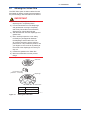
(b) When storing the transmitter, repack it carefully in
the packaging that it was originally shipped with.
Process connector gasket
Bolt
F0201.ai
Figure 2.1
Transmitter Mounting Hardware
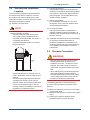
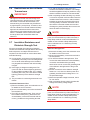
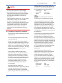
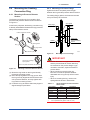
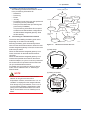
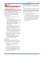
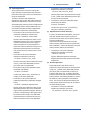
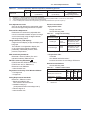
2.1 Model and Specifications
Check
The model name and specifications are written on
the name plate attached to the case.
MODEL
SUFFIX
SUPPLY
OUTPUT
MWP
STYLE
mA DC
V DC
NO.
: Refer to USER'S MANUAL.
F0202.ai
Figure 2.2
Name Plate
(d) Preferably remove the batteries for storage. For
maximum battery life, the storage temperature
should not exceed 30°C.
NOTE
CAL
RNG
Made in Japan
TOKYO 180-8750 JAPAN
(c) If the transmitter has been used, thoroughly
clean the chambers inside the cover flanges, so
that there is no process fluid remaining inside.
Before placing it in storage, also make sure that
the pressure-detector is securely connected to
the transmitter section.
When storing the instrument with a battery
pack, it is recommended to put the instrument in
Deep Sleep mode to conserve the batteries. For
details on how to switch to Deep Sleep mode,
refer to subsection 8.3.13 “Switching to Deep
Sleep Mode”.
IM 01C27C01-01EN
2-2
<2. Handling Cautions>
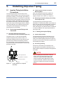
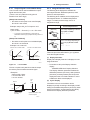
2.4 Selecting the Installation
Location
The transmitter is designed to withstand severe
environmental conditions. However, to ensure
that it will provide years of stable and accurate
performance, take the following precautions when
selecting the installation location.
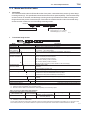
(a) Wireless Communication
NOTE
The installation location of this transmitter must
meet the following conditions:
- Adjust the direction of the antenna to be
in the upright position regardless of the
orientation of this transmitter. See section 4
for adjusting the antenna.
- Install the transmitter at least 1.5m above
the ground or floor.
(b) Ambient Temperature
Avoid locations subject to wide temperature
variations or a significant temperature gradient.
If the location is exposed to radiant heat from
plant equipment, provide adequate thermal
insulation and/or ventilation.
(c) Ambient Atmosphere
Do not install the transmitter in a corrosive
atmosphere. If this cannot be avoided, there
must be adequate ventilation.
(d) Shock and Vibration
Although the transmitter is designed to be
relatively resistant to shock and vibration, an
installation site should be selected where this is
kept to a minimum.
(e) Installation of Explosion-protected Transmitters
An explosion-protected transmitters is
certified for installation in a hazardous area
containing specific gas types. See subsection
2.8 “Installation of an Explosion-Protected
Transmitters.”
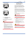
2.5 Pressure Connection
WARNING
at least
1.5m
F0203.ai
-
-
Ensure that there are no obstacles such as
walls or pipes within a 30-cm radius of each
antenna.
Confirm that each field wireless equipment
compliant with ISA100.11a can see the
antenna of other devices which locate within
its own communication range. In the star
topology network, the visibility to the antenna
of gateway is a mandatory clause.
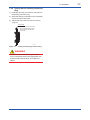
• Never loosen the process connector bolts
and flange bolts when an instrument is
installed in a process. The device is under
pressure, and a loss of seal can result in a
sudden and uncontrolled release of process
fluid.
• When draining toxic process fluids that have
condensed inside the pressure detector,
take appropriate steps to prevent the contact
of such fluids with the skin or eyes and the
inhalation of vapors from these fluids.
The following precautions must be observed
in order to safely operate the transmitter under
pressure.
(a) Make sure that all the process connector bolts
are tightened firmly.
(b) Make sure that there are no leaks in the impulse
piping.
(c) Never apply a pressure higher than the
specified maximum working pressure.
IM 01C27C01-01EN
2.6 Restrictions on Use of Radio
Transceivers
IMPORTANT
Although the transmitter has been designed to
resist high frequency electrical noise, if a radio
transceiver is used near the transmitter or its
external wiring, the transmitter may be affected
by high frequency noise pickup. To test this, start
out from a distance of several meters and slowly
approach the transmitter with the transceiver
while observing the measurement loop for noise
effects. Thereafter use the transceiver outside
the range where the noise effects were first
observed.
2.7 Insulation Resistance and
Dielectric Strength Test
Since the transmitter has undergone insulation
resistance and dielectric strength tests at the factory
before shipment, normally these tests are not
required. If the need arises to conduct these tests,
heed the following:
(a) Do not perform such tests more frequently than
is absolutely necessary. Even test voltages that
do not cause visible damage to the insulation
may degrade the insulation and reduce safety
margins.
(b) Never apply a voltage exceeding 500 V DC
(100 V DC with an internal lightning protector)
for the insulation resistance test, nor a voltage
exceeding 500 V AC (100 V AC with an internal
lightning protector) for the dielectric strength
test.
(c) The procedure for conducting these tests is as
follows:
• Insulation Resistance Test
1)Remove the battery pack. See subsection 9.4.5
for details on how to remove it.
2)Short-circuit the battery connection terminals in
the terminal box.
3)Turn OFF the insulation tester. Then connect
the insulation tester plus (+) lead wire to the
shorted battery connection terminals and the
minus (–) leadwire to the grounding terminal.
<2. Handling Cautions>
2-3
4)Turn ON the insulation tester power and
measure the insulation resistance. The voltage
should be applied as briefly as possible to verify
that the insulation resistance is at least 20 MΩ.
5)After completing the test and being very careful
not to touch exposed conductors disconnect the
insulation tester and connect a 100 kΩ resistor
between the grounding terminal and the shortcircuiting battery connection terminals. Leave
this resistor connected at least one second to
discharge any static potential. Do not touch the
terminals while it is discharging.
NOTE
When storing the instrument with a battery
pack, it is recommended to put the instrument in
Deep Sleep mode to conserve the batteries. For
details on how to switch to Deep Sleep mode,
refer to subsection 8.3.13 “Switching to Deep
Sleep Mode”.
• Dielectric Strength Test
1)Remove the battery pack. See subsection 9.4.5
for details on how to remove it.
2)Short-circuit the battery connection terminals in
the terminal box.
3)Turn OFF the dielectric strength tester. Then
connect the tester between the shorted battery
connection terminals and the grounding
terminal. Be sure to connect the grounding lead
of the dielectric strength tester to the ground
terminal.
4)Set the current limit on the dielectric strength
tester to 0.1 mA, then turn ON the power and
gradually increase the test voltage from ‘0’ to
the specified voltage.
5)When the specified voltage is reached, hold it
for one minute.
6)After completing this test, slowly decrease the
voltage to avoid any voltage surges.
NOTE
When storing the instrument with a battery
pack, it is recommended to put the instrument in
Deep Sleep mode to conserve the batteries. For
details on how to switch to Deep Sleep mode,
refer to subsection 8.3.13 “Switching to Deep
Sleep Mode”.
IM 01C27C01-01EN
2.8 Installation of an ExplosionProtected Instrument
If a customer makes a repair or modification to an
intrinsically safe instrument and the instrument is
not restored to its original condition, its intrinsically
safe construction may be compromised and the
instrument may be hazardous to operate. Please
contact Yokogawa before making any repair or
modification to an instrument.
CAUTION
This instrument has been tested and certified
as being intrinsically safe. Please note that
severe restrictions apply to this instrument’s
construction, installation, external wiring,
maintenance and repair. A failure to abide by
these restrictions could make the instrument a
hazard to operate.
<2. Handling Cautions>
2-4
Groups IIC, in Hazardous Locations.
• Enclosure: NEMA 4X (Indoors and outdoors).
• Temperature Class: T4
• Ambient temperature: -50 to 70°C
Note 2. Installation
• Installation should be in accordance with
ANSI/ISA-RP12.06.01 and the National
Electric Code (NFPA 70).
• Dust-tight conduit seal must be used when
installed in a Class II, III, Group E, F and G
environments.
• Note a warning label worded
“SUBSTITUTION OF COMPONENTS MAY
IMPAIR INTRINSIC SAFETY,” and “INSTALL
IN ACCORDANCE WITH DOC. NO.
IFM037-A20”.
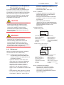
[Installation Diagram]
Amplifier housing code 7
Hazardous Location
Transmitter
WARNING
The battery pack may be replaced in a
hazardous area. The battery pack has
surface resistivity greater than 1G ohm and
must be properly installed in the enclosure
of the transmitter. Care must be taken during
transportation to and from the point of installation
to prevent electrostatic charge build-up.
Battery Pack
[Intrinsically Safe]
Class I, II, III, Division 1,
Groups A,B,C,D,E,F,G
Class I, Zone 0
in Hazardous (Classified)
Locations
AEx ia IIC
Amplifier housing codes other than 7
Hazardous Location
Arrester
(*1, *2)
2.8.1 FM Approval
Caution for FM intrinsically safe type. (Following
contents refer “DOC. No. IFM037-A20”)
Note 1. Model EJX Series Differential, gauge
and absolute pressure transmitters with
optional code /FS17 are applicable for use
in hazardous locations.
• Applicable Standard: Class 3600, Class
3610, Class 3611, Class 3810, NEMA 250,
ANSI/ISA-60079-0, ANSI/ISA-60079-11
• Intrinsically Safe for Class I, Division 1,
Groups A, B, C & D, Class II, Division 1,
Groups E, F & G and Class III, Division 1,
Class I, Zone 0, in Hazardous Locations, AEx
ia IIC
• Nonincendive for Class I, Division 2, Groups
A, B, C & D, Class II, Division 2, Groups F &
G and Class III, Division 1, Class I, Zone 2,
[Nonincendive]
Class I, II, Division 2,
Groups A,B,C,D,F,G
Class III, Division 1.
Class I, Zone 2, Group IIC,
in Hazardous (Classified)
Locations
Antenna
(*1)
Antenna Connector
Transmitter
Battery Pack
*1: These apparatus are simple apparatus.
*2: Arrester may not be connected.
[Intrinsically Safe]
Class I, II, III, Division 1,
Groups A,B,C,D,E,F,G
Class I, Zone 0
in Hazardous (Classified)
Locations
AEx ia IIC
[Nonincendive]
Class I, II, Division 2,
Groups A,B,C,D,F,G
Class III, Division 1.
Class I, Zone 2, Group IIC,
in Hazardous (Classified)
Locations
F0210.ai
Note 3. Maintenance and Repair
• The instrument modification or parts
replacement by other than authorized
representative of Yokogawa Electric
Corporation is prohibited and will void FM
Approvals approval.
IM 01C27C01-01EN
Note 4. Battery Pack
USE ONLY BATTERY PACK YOKOGAWA
F9915MA OR F9915NS.
Note 5. Special Conditions for safe use
POTENTIAL ELECTROSTATIC CHARGING
HAZARD-SECURE DISTANCE OF 100MM
FROM ANTENNA.
DO NOT OPEN WHEN CL II, III, DIV 1,2
ATMOSPHERE IS PRESENT.
2.8.2 CSA Certification
Caution for CSA Intrinsically safe type. (Following
contents refer to “DOC No. ICS030”)
Note 1. Model EJX Series differential, gauge,
and absolute pressure transmitters with
optional code /CS17 are applicable for use
in hazardous locations
Certificate: 2325443
• Applicable standard: CAN/CSA-C22.2 No.0,
CAN/CSA-C22.2 No.0.4, C22.2 No.25,
CAN/CSA-C22.2 No.94,
CAN/CSA-C22.2 No.157, C22.2 No.213,
CAN/CSA-C22.2 No.61010-1,
CAN/CSA- C22.2 No.60079-0,
CAN/CSA-E60079-11, IEC60529
• Ex ia IIC T4
• Intrinsically Safe for Class I, Division 1,
Groups A, B, C & D, Class II, Division 1,
Groups E, F & G, Class III, Division 1
• Nonincendive for Class I, Division2,
Groups A, B, C & D, Class II, Division2,
Groups F & G, Class III, Division1
• Enclosure: IP66/IP67 and Type 4X
• Temperature Code: T4
• Ambient Temperature: –50 to 70°C
• Max. Process Temp.: 120°C
Note 2. Installation
• Installation should be in accordance with
Canadian Electrical Code Part I and Local
Electrical Code.
• Do not alter drawing without authorization
from CSA.
• The instrument modification or parts
replacement by other than authorized
representative of Yokogawa Electric
Corporation is prohibited and will void
Canadian Standards Intrinsically safe and
nonincendive Certification.
2-5
<2. Handling Cautions>
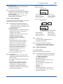
[Installation Diagram]
Amplifier housing code 7
Hazardous Area
Transmitter
Battery Pack
[Intrinsically Safe]
Group IIC, Zone 0
Class I, II, III, Division 1,
Groups A,B,C,D,E,F,G
[Nonincendive]
Class I, II, Division 2,
Groups A,B,C,D,F,G
Class III, Division 1
Amplifier housing code 8 and 9
Hazardous Area
Arrester
(*1, *2)
Antenna
(*1)
Antenna Connector
Transmitter
Battery Pack
*1: These apparatus are simple apparatus.
*2: Arrester may not be connected.
[Intrinsically Safe]
Group IIC, Zone 0
Class I, II, III, Division 1,
Groups A,B,C,D,E,F,G
[Nonincendive]
Class I, II, Division 2,
Groups A,B,C,D,F,G
Class III, Division 1
F0205.ai
Note 3. Battery Pack
• Use only YOKOGAWA battery pack
F9915MA or F9915NS.
Note 4. Special Conditions for safe use
• Potential electrostatic charging hazard secure distance of 100mm from antenna.
2.8.3 ATEX Certification
(1) Technical Data
Caution for ATEX Intrinsically safe type.
Note 1. Model EJX Series pressure transmitters
with optional code /KS27 for potentially
explosive atmospheres:
• No. KEMA 10ATEX0164 X
• Applicable Standard:
EN 60079-0:2009, EN 60079-11:2012,
EN 60079-26:2007
• Type of Protection and Marking code:
Ex ia IIC T4 Ga
• Group: II
• Category: 1 G
• Ambient Temperature: –50°C to 70°C
• Process Temperature (Tp.): 120°C max.
• Enclosure: IP66/IP67
IM 01C27C01-01EN
2-6
<2. Handling Cautions>
Note 2. Installation
• Installation should be in accordance with
local installation requirements. (Refer to the
Control Drawing)
(2) Operation
WARNING
Take care not to generate mechanical sparking
when access to the instrument and peripheral
devices in a hazardous location.
[Control Drawing]
Amplifier housing code 7
Hazardous Area
Transmitter
(3) Maintenance and repair
Battery Pack
WARNING
Amplifier housing code 8 and 9
Hazardous Area
Arrester
(*1, *2)
The instrument modification or parts replacement
by other than an authorized Representative of
Yokogawa Electric Corporation is prohibited and
will void the certification.
Antenna
(*1)
Antenna connector
Transmitter
Battery Pack
*1: These apparatus are simple apparatus.
*2: Arrester may not be connected.
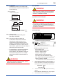
(4) Name Plate
• Name Plate
F0206.ai
Note 3. Battery Pack
• Use only YOKOGAWA battery pack
F9915MA or F9915NS.
Note 4. Special conditions for Safe Use
• In case the enclosure of the Pressure
Transmitter is made of aluminum, if it
is mounted in an area where the use of
category 1 G apparatus is required, it must
be installed such, that, even in the event of
rare incidents, ignition sources due to impact
and friction sparks are excluded.
MODEL
SUFFIX
SUPPLY
OUTPUT
MWP
mA DC
V DC
NO.
Made in Japan
TOKYO 180-8750 JAPAN
: Refer to USER'S MANUAL.
F0207.ai
• Tag plate for intrinsically safe type
KS27
*3
WARNING
No. KEMA 10ATEX0164 X
Ex ia IIC T4 Ga
ENCLOSURE: IP66/IP67
Tamb.: -50 TO 70°C
MAX PROCESS TEMP.: 120°C
POTENTIAL ELECTROSTATIC CHARGING HAZARD - SECURE DISTANCE
OF 100MM FROM ANTENNA.
USE ONLY BATTERY PACK YOKOGAWA F9915MA OR F9915NS.
POTENTIAL ELECTROSTATIC CHARGING HAZARD - SEE USER'S MANUAL.
F0208.ai
MODEL: Specified model code.
STYLE: Style code.
SUFFIX: Specified suffix code.
SUPPLY: Supply voltage.
OUTPUT: Output signal.
MWP: Maximum working pressure.
CAL RNG: Specified calibration range.
NO.: Serial number and year of production *1.
TOKYO 180-8750 JAPAN:
The manufacturer name and the address *2.
• For applications in explosive atmospheres
caused by gases, vapors or mists and
where category 1 G apparatus is required,
electrostatic charges on the non-metallic
parts of the Pressure Transmitter shall be
avoided.
WARNING
Potential electrostatic charging hazard - secure
distance of 100mm from antenna.
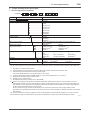
CAL
RNG
STYLE
*1:
The first digit in the final three numbers of the serial
number appearing after “NO.” on the nameplate indicates
the year of production. The following is an example of a
serial number for a product that was produced in 2010:
91K819857 032
↑
The year 2010
*2:
“180-8750” is a zip code which represents the following
address.
2-9-32 Nakacho, Musashino-shi, Tokyo Japan
*3: The identification number of Notified Body.
IM 01C27C01-01EN
2-7
<2. Handling Cautions>
2.8.4 IECEx Certification
Caution for IECEx Intrinsically safe type.
Note 1. Model EJX Series pressure transmitters
with optional code /SS27 for potentially
explosive atmospheres:
• No. IECEx KEM 10.0074X
• Applicable Standard:
IEC 60079-0:2011, IEC 60079-11:2011,
IEC 60079-26:2006
• Type of Protection and Marking code:
Ex ia IIC T4 Ga
• Ambient Temperature: –50°C to 70°C
• Process Temperature (Tp.): 120°C max.
• Enclosure: IP66/IP67
Note 2. Installation
• Installation should be in accordance with
local installation requirements.
(Refer to the Control Drawing)
Note 4. Battery Pack
• Use only YOKOGAWA battery pack
F9915MA or F9915NS.
Note 5. Special conditions for Safe Use
• In case the enclosure of the Pressure
Transmitter is made of aluminum, if it
is mounted in an area where the use of
apparatus of equipment protection level Ga
is required, it must be installed such, that,
even in the event of rare incidents, ignition
sources due to impact and friction sparks are
excluded.
• For applications in explosive atmospheres
caused by gases, vapors or mists and
mounted in an area where the use of
apparatus of equipment protection level Ga
is required, electrostatic charges on the nonmetallic parts of the Pressure Transmitter
shall be avoided.
[Control Drawing]
WARNING
Amplifier housing code 7
Hazardous Area
•
Transmitter
•
Battery Pack
Amplifier housing code 8 and 9
Hazardous Area
Arrester
(*1, *2)
Potential electrostatic charging hazard secure distance of 100mm from antenna.
Take care not to generate mechanical
sparking when access to the instrument and
peripheral devices in a hazardous location.
Antenna
(*1)
2.9 EMC Conformity Standards
Antenna connector
EN61326-1 Class A, Table 2 (For use in
industrial locations), EN61326-2-3
Transmitter
Battery Pack
*1: These apparatus are simple apparatus.
*2: Arrester may not be connected.
F0209.ai
Note 3. Maintenance and Repair
• The instrument modification or parts
replacement by other than authorized
representative of Yokogawa Electric
Corporation is prohibited and will void IECEx
Intrinsically safe Certification.
WARNING
The instrument modification or parts replacement
by other than an authorized Representative of
Yokogawa Electric Corporation is prohibited and
will void the certification.
CAUTION
This instrument is a Class A product, and it is
designed for use in the industrial environment.
Please use this instrument in the industrial
environment only.
2.10 Pressure Equipment
Directive (PED)
(1) General
• EJX Series pressure transmitters are
categorized as piping under the pressure
accessories section of directive 97/23/EC,
which corresponds to Article 3, Paragraph 3 of
PED, denoted as Sound Engineering Practice
(SEP).
IM 01C27C01-01EN
(2) Technical Data
Article 3, Paragraph 3 of PED, denoted as
Sound Engineering Practice (SEP).
(3) Operation
CAUTION
• The temperature and pressure of fluid should
be maintained at levels that are consistent
with normal operating conditions.
• The ambient temperature should be
maintained at a level that is consistent with
normal operating conditions.
• Please take care to prevent water hammer
and the like from inducing excessive
pressures in pipes and valves. If phenomena
are likely, install a safety valve or take
some other appropriate measure to prevent
pressure from exceeding PS.
• Take appropriate measures at the device or
system level to protect transmitters if they
are to be operated near an external heat
source.
2.11 Low Voltage Directive
Applicable standard:
EN61010-1, EN61010-2-030
(1) Pollution Degree 2
"Pollution degree" describes the degree to
which a solid, liquid, or gas which deteriorates
dielectric strength or surface resistivity is
adhering. " 2 " applies to normal indoor
atmosphere. Normally, only non-conductive
pollution occurs. Occasionally, however,
temporary conductivity caused by condensation
must be expected.
(2) Installation Category I
(Anticipated transient overvoltage 330 V)
2-8
<2. Handling Cautions>
2.12 Regulatory Compliance
for Radio and
Telecommunication
Please confirm that a installation region fulfils
a standards, require additional regulatory
information and approvals, contact to
Yokogawa Electric Corporation.
2.12.1 Radio and Telecommunications
Terminal Equipment Directive (R&TTE)
We, Yokogawa Electric Corporation hereby
declare that this equipment, model EJX-L series
is in compliance with the essential requirements
and other relevant provisions of Directive
1999/5/EC.
The CE declaration of conformity for R&TTE
for this product can be found at http://www.
yokogawa.com/fld/
2.12.2 FCC compliance
This equipment contains transmitter module
FCC ID: SGJ-WFC001.
This device complies with Part 15 of FCC
Rules. Operation is subject to the following
two conditions: (1) this device may not cause
interference, and (2) this device must accept
any interference, including interference that
may cause undesired operation of this device.
Co-located:
This transmitter must not be co-located or
operated in conjunction with any other antenna
or transmitter.
FCC WARNING:
Changes or modifications not expressly
approved by the party responsible for
compliance could void the user’s authority to
operate the equipment.
"Overvoltage category (Installation category)"
describes a number which defines a transient
overvoltage condition. It implies the regulation
for impulse withstand voltage. " I " applies to
electrical equipment which is supplied from the
circuit when appropriate transient overvoltage
control means (interfaces) are provided.
IM 01C27C01-01EN
NOTE
This equipment has been tested and found
to comply with the limits for a Class A digital
device, pursuant to part 15 of the FCC Rules.
These limits are designed to provide reasonable
protection against harmful interference when
the equipment is operated in a commercial
environment.
This equipment generates, uses, and can radiate
radio frequency energy and, if not installed
and used in accordance with the instruction
manual, may cause harmful interference to radio
communications. Operation of this equipment
in a residential area is likely to cause harmful
interference in which case the user will be
required to correct the interference at his own
expense.
2.12.3 Industry Canada (IC) compliance
This equipment contains transmitter module IC:
8999A-WIC001.
This Class A digital apparatus complies with
Canadian ICES-003.
This device complies with Industry Canada
license-exempt RSS standard(s). Operation is
subject to the following two conditions: (1) this
device may not cause interference, and (2) this
device must accept any interference, including
interference that may cause undesired,
operation of the device.
Under Industry Canada regulations, this
radio transmitter may only operate using an
antenna of a type and maximum (or lesser)
gain approved for the transmitter by Industry
Canada. To reduce potential radio interference
to other users, the antenna type and its gain
should be so chosen that the equivalent
isotropically radiated power (e.i.r.p.) is not
more than that necessary for successful
communication.
This radio transmitter IC Number
8999A-WIC001 has been approved by Industry
Canada to operate with the antenna types
listed below with the maximum permissible
gain and required antenna impedance for each
<2. Handling Cautions>
2-9
antenna type indicated. Antenna types not
included in this list, having a gain greater than
the maximum gain indicated for that type, are
strictly prohibited for use with this device.
Antenna type:
Gain:
COLLINEAR
9 dBi, 50 Ω
Sleeve
2.14 dBi, 50 Ω
French:
Cet appareil numérique de la classe A est
conforme à la norme NMB-003 du Canada.
Le présent appareil est conforme aux CNR
d’Industrie Canada applicables aux appareils
radio exempts de licence. L’exploitation est
autorisée aux deux conditions suivantes : (1)
l’appareil ne doit pas produire de brouillage,
et (2) l’utilisateur de l’appareil doit accepter
tout brouillage radioélectrique subi, même si le
brouillage est susceptible d’en compromettre le
fonctionnement.
Conformément à la réglementation d’Industrie
Canada, le présent émetteur radio peut
fonctionner avec une antenne d’un type et
d’un gain maximal (ou inférieur) approuvé pour
l’émetteur par Industrie Canada. Dans le but de
réduire les risques de brouillage radioélectrique
à l’intention des autres utilisateurs, il faut choisir
le type d’antenne et son gain de sorte que
la puissance isotrope rayonnée équivalente
(p.i.r.e.) ne dépasse pas l’intensité nécessaire
à l’établissement d’une communication
satisfaisante.
Le présent émetteur radio IC Number
8999A-WIC001 a été approuvé par Industrie
Canada pour fonctionner avec les types
d’antenne énumérés ci-dessous et ayant
un gain admissible maximal et l’impédance
requise pour chaque type d’antenne. Les types
d’antenne non inclus dans cette liste, ou dont
le gain est supérieur au gain maximal indiqué,
sont strictement interdits pour l’exploitation de
l’émetteur.
Antenne type:
Gain:
COLLINEAR
9 dBi, 50 Ω
Sleeve
2.14 dBi, 50 Ω
IM 01C27C01-01EN
3.
3-1
<3. Component Names>
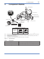
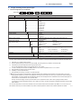
Component Names
Antenna (Note 3)
Ground terminal
Zero-adjustment screw
Process connection
(Low pressure side)
Integral indicator
Cover flange
RF assembly
Slide Mounting
switch screw
Transmitter section
Bolt
CPU assembly
Write protection switch
D
Process connector
E WR
Amplifier Cover
Not in use
Hardware write protection switch (WR)
Write protection
Switch Position
(Note 1)
Write protection
D
E
D
E
L
H
L
H
NO
(Write enabled)
YES (Note 2)
(Write disabled)
F0301.ai
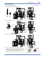
Note 1: Set the switch as shown in the figure above to set the write protection. The hardware write protection switch is set to E side. Set
to H side for the switch of not-in-use.
Note 2: When the switch is D side (write protection setting), provisioning is acceptable. For details of provisioning, refer to section 7.4
“ Connecting to the Field Wireless Network “.
Note 3: The detachable antenna is applied when the amplifier housing code 7 or 8 is specified.
Figure 3.1
Component Names
Table 3.1
Display Symbol
Display Symbol
▲
Meaning of Display Symbol
The output signal being zero-adjusted is increasing.
▼
The output signal being zero-adjusted is decreasing.
Write protect function is enabled.
IM 01C27C01-01EN
4.
<4. Installation>
4-1
Installation
4.1 Precautions
Before installing the transmitter, read the cautionary
notes in Section 2.4, “Selecting the Installation
Location.” For additional information on the
ambient conditions allowed at the installation
location, refer to Subsection 11.1 “Standard
Specifications.”
NOTE
To connect this transmitter to the field wireless
network, the information on connecting to field
wireless devices needs to be set beforehand.
Refer to 7.4 “Connecting to the Field Wireless
Network.”
IMPORTANT
• When welding piping during construction,
take care not to allow welding currents to
flow through the transmitter.
• Do not step on this instrument after
installation.
• Never loosen the four bolts securing the
cover flanges (Refer to figure 3.1.) If the seal
liquid leaks, the transmitter cannot be used.
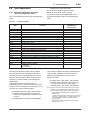
4.2 Mounting
The transmitter is mounted on a process using its
high-pressure side flange as shown in Figure 4.1.
The mating flange, gasket, stud bolts and nuts are
to be procured by the customer.
IMPORTANT
Please use a gasket with an inside diameter
(ød) that is greater than the diameter of the
diaphragm seal. If a gasket with a smaller
inside diameter is used, the diaphragm may
not function correctly. (Refer to Subsection 11.4
‘Dimensions’)
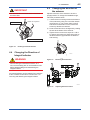
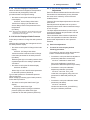
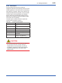
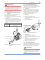
4.3 Rotating Transmitter Section
WARNING
Intrinsic safe type transmitters must be, as a rule,
do not rotate transmitter section if it is powered.
In case you need to rotate when the transmitter
is powered, using gas detector and confirm no
existence of explosive gas before rotating.
The transmitter section can be rotated in either
direction to any desired position. Note that there is
a stopper which prevents the transmitter from being
rotated more than 360°.
1) Using the Allen wrench, remove the five
setscrews securing the transmitter section to
the capsule assembly.
2) Rotate the transmitter section slowly to the
desired position.
3) Tighten the five setscrews to a torque of 1.5
N·m {15 kgf·cm}.
Gasket
Stud bolt
Nut
Figure 4.1
F0401.ai
Transmitter Mounting
IM 01C27C01-01EN
4-2
<4. Installation>
4.5 Changing the direction of
the antenna
IMPORTANT
Do not rotate the transmitter section more than
the above limit.
Transmitter section
Rotate 180° segments
Pressure-detector section
Adjust the direction of the antenna to be in the
upright position. To change the installation angle,
follow the procedure below.
1) Loosen the two mounting screws at the bottom
of the antenna by using a 2.5 mm Allen wrench
(see Figure 4.3). The screws might come off
and be lost if loosened too much; loosen the
screws by about three rotations.
2) Press forward and down 90 degrees by rotating
the axis at the bottom of the antenna.
3) Tighten the two screws to a torque of 1.5 N·m
by using a torque wrench. When doing this, be
careful not leave a gap between the antenna
and housing.
F0402.ai
Figure 4.2
Rotating Transmitter Section
4.4 Changing the Direction of
Integral Indicator
WARNING
F0403.ai
Figure 4.3
Mounting Screw Position
Figure 4.4
Adjusting Antenna Position
Intrinsic safe type transmitters must be, as a
rule, remove battery pack in non-hazardous area
before disassembling and reassembling the
integral indicator.
An integral indicator can be rotated in four positions
at 90°. Follow the instructions in section 9.4.1 for
removing and attaching the integral indicator.
F0404.ai
IM 01C27C01-01EN
4-3
<4. Installation>
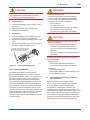
4.6 Mounting the Flushing
Connection Ring
4.6.2 Mounting to Process Flange
Tighten the bolts to completely close the gap
between the ring and the pressure detector section.
4.6.1 Mounting to Pressure Detector
Section
The flushing connection ring is mounted to high
pressure side pressure detector section as shown
in Figure 4.5.
At the factory shipment, the flushing connection ring
is already assembled and attached to high pressure
side process detector section.
The mating flange, gasket, stud bolts and nuts are
to be procured by the customer.
Spiral gasket
Mating flange
Ring
Pressure-detector section
Diaphragm
Gasket
Ring
Pressure-detector
section
Spiral gasket
Ring holder
Drain/vent plug
F0406.ai
Figure 4.6
IMPORTANT
Groove for installing
spiral gasket
View from pressure detector section side
F0405.ai
Figure 4.5
Mounting to Process Flange
Mounting to Pressure Detector Section
(1) Mount the ring holder on the ring and loosely
tighten the mounting screws.
(2) Place the spiral gasket in the ring groove. With
the ring correctly aligned and flush with the face
of the pressure detector, securely tighten each
ring holder’s mounting screws.
(3) Position the ring so that the drain/vent plugs are
aligned straight up and down.
• Confirm that there is no gap between the ring
and the process-detector section after they
are mounted on the process flange. A gap
can lead to a sudden, explosive release of
process fluids.
• When mounting or removing the ring,
take care not to tilt the pressure detector
downward as the ring can slip off and cause
injury.
• When re-mounting the ring, use the new
spiral gasket as shown in below table.
Table 4.1
Part number
F9350SV
F9970XF
F9350ST
F9970XD
F9346ZH
F9970XB
*:
**:
Spiral Gasket for Pressure Detector
Section Side*
Size
ø100×ø120×t4.5
ø100×ø120×t4.5
ø70×ø90×t4.5
ø70×ø90×t4.5
ø60×ø75×t4.5
ø60×ø75×t4.5
Description
For 3-inch flange
For 3-inch flange**
For 2-inch flange
For 2-inch flange**
For 1 1/2-inch flange
For 1 1/2-inch flange**
Material; 316SST (Hoop), PTFE Teflon (Filler)
For oil-prohibited use (Option code: /K1, /K5)
IM 01C27C01-01EN
<4. Installation>
4-4
4.7 Affixing the Teflon Film
The FEP Teflon option includes a teflon film and
fluorinated oil. Before mounting the transmitter to
the process flange, affix the teflon film as follows:
IMPORTANT
1) Position the diaphragm so that the
diaphragm is in a upward position.
2) Pour the fluorinated oil on the diaphragm
and gasket area covering it completely
and evenly. Be careful not to scratch the
diaphragm or change the its shape.
3) Affix the teflon film over the diaphragm and
gasket area.
4) Next, carefully inspect the cover and try
to identify any entrapped air between
the diaphragm and the teflon film. The
air must be removed to ensure optimum
performance. If air pockets are present, use
your fingers to remove the air by starting at
the center of the diaphragm and work your
way out.
5) Position the gasket on the Teflon film.
6) Mount the transmitter onto the process
flange.
Teflon film
Fluorinated oil
[PART No. : F9145YN]
Diaphragm
Gasket area
Figure 4.7
PART No.
Prosess Flange size
F9347XA
3 inch (80mm)
F9347YD
2 inch (50mm)
F0407.ai
Affixing the Teflon Film
IM 01C27C01-01EN
5.
5-1
<5. Installing Impulse Piping>
Installing Impulse Piping
5.1 Impulse Piping Installation
Precautions
The impulse piping that connects the process
outputs to the transmitter must convey the process
pressure accurately. If, for example, gas collects in
a liquid-filled impulse line, or the drain of a gas-filled
impulse line becomes plugged, it will not convey the
pressure accurately. Since this will cause errors in
the measurement output, select the proper piping
method for the process fluid (gas, liquid, or steam).
Pay careful attention to the following points when
routing the impulse piping and connecting the
impulse piping to a transmitter.
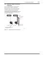
5.1.1 Connecting Impulse Piping to the
Transmitter
(1) Check the High and Low Pressure
Connections on the Transmitter (Figure 5.1)
The letters H and L on the capsule assembly
indicate the high and low pressure sides. For
liquid level measurement in an open tank, the low
pressure side measures atmospheric pressure.
For a closed tank, connect the impulse line to the
low pressure side of the transmitter to measure the
pressure in the tank.
(2) Tightening the Process Connector
Mounting Bolts
After connecting the impulse line, tighten the
process connector mounting bolts uniformly.
( Apply a torque of 39 ~ 49N·m { 4 ~ 5kgf·m} )
(3) Removing the Impulse Piping Connecting
Port Dustproof Cap
The impulse piping connecting port of the
transmitter is covered with a plastic cap to keep out
dust. This cap must be removed before connecting
the line. (Be careful not to damage the threads
when removing this cap. Never insert a screwdriver
or other tool between the cap and port threads to
remove the cap.)
5.1.2 Routing the Impulse Piping
(1) Impulse Piping Slope
The impulse piping must be routed with only an
upward or downward slope. Even for horizontal
routing, the impulse piping should have a slope of
at least 1/10 to prevent condensate (or gases) from
accumulating in the pipes.
(2) Preventing Freezing
If there is any risk that the process fluid in the
impulse piping or transmitter could freeze, use a
steam jacket or heater to maintain the temperature
of the fluid.
NOTE
H and L appear here
Low pressure connection
Process connector
Bolt
Figure 5.1
F0501.ai
H and L Symbols on a Capsule
Assembly
After completing the connections, close the
valves on the process pressure taps (main
valves), the valves at the transmitter (stop
valves), and the impulse piping drain valves,
so that condensate, sediment, dust and other
extraneous material cannot enter the impulse
piping.
IM 01C27C01-01EN
<5. Installing Impulse Piping>
5-2
5.2 Impulse Piping Connection
Examples
Figure 5.2 shows examples of typical impulse
piping connections. Before connecting the
transmitter to the process, study the transmitter
installation location, the process piping layout,
and the characteristics of the process fluid
(corrosiveness, toxicity, flammability, etc.), etc. and
make appropriate changes and additions to the
connection configurations.
Open Tank
Closed Tank
Tap valve
Union or flange
Vent plug
Tee
Drain valve
Drain plug
Pipe (opened to atmosphere
at low pressure side)
F0502.ai
Figure 5.2
Impulse Piping Connection Examples
IM 01C27C01-01EN
6.
<6. Wiring>
6-1
Wiring
6.1 Mounting Antenna and
Wiring
For Amplifier housing code 8 and 9, an antenna
is not attached to the transmitter. The following
provides the instructions for mounting the antenna
and installing the remote antenna and wiring using
antenna extension cable.
IMPORTANT
The antenna connector is covered with a cap
at the time of delivery. Keep the cap attached
until the installation of the antenna or antenna
cables to protect the inside connection part.
The unscrewed cap should be stored in order
to replace it immediately after the antenna or
antenna cables are removed.
Antenna connector
CAUTION
To maintain the ultimate conditions of radiofrequency signal, protect the connectors of
antenna, extension antenna cable, and arrester
from the corrosive atmosphere by the following
treatment.
1. Clean the connection to be protected.
2. Wind the butyl rubber self-bonding tape
around the connection. See the manual of
the tape about the winding.
3. To protect the butyl rubber self-bonding tape
from the environment such as ultraviolet rays
and so on, wind vinyl tape (or a vinyl type
self-bonding tape) on it.
F0601.ai
Figure 6.1
CAUTION
When installing the antenna, screw the antenna
by tightening the lower nut part. Screwing the
antenna by holding the antenna body may cause
failure such as cable disconnection. The same
manner should be taken when unscrewing the
antenna.
Antenna body
6.1.1 Mounting the antenna
Screw the provided antenna into the antenna
connector of the transmitter. The antenna may
be sold as available accessories and supplied
separately.
1.Unscrew the antenna connector cap on the
antenna connector.
2.Screw the provided antenna into the antenna
connector. Tighten the antenna connector with
a torque of 2 to 3 N∙m.
Mounting the antenna
Nut part
F0602.ai
Figure 6.2
Antenna
IM 01C27C01-01EN
6-2
<6. Wiring>
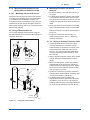
6.1.2 Mounting External Antenna and
Wiring Antenna Extension Cable
6.1.2.1 Mounting of External Antenna
Mount the external antenna at the proper location
according to the wireless environment described
in 2.4 Selecting the Installation Location. The
mounting to the pipe such as 50 mm (2-inch) pipe
needs to secure the enough strength to endure a
strong wind, vibration and so on. The antenna must
be mounted vertically.
Fixing of External Antenna
Fix an external antenna appropriately using the
bracket provided as the external antenna option to
50 mm (2-inch) pipe.
Mounting Procedure of External
Antenna
1.Fix the bracket by U-bolt and nut to 50 mm (2inch) pipe.
2.Fix the antenna extension cable to the bracket
1 using the provided nut with a torque of 6 to 7
N∙m as shown in the Figure 6.3 above. Use the
nut which is attached to the antenna extension
cable.
3.Screw the antenna into the antenna connector
of the antenna extension cable on the bracket
1.
Tighten the antenna connector with a torque of
2 to 3 N∙m.
4.Protect the connection as necessary. For
details of the protection, see “6.1 Mounting
Antenna and Wiring.”
6.1.2.2 Wiring of Antenna Extension Cable
Vertical pipe
mounting
1.Use the provided antenna extension cable
to connect the antenna connector with the
external antenna. Tighten the connector of the
antenna extension cable with a torque of 2
to 3 N∙m. The minimum bending radius while
checking the wiring position should be more
than 200 mm.
2.When using two extension cables, the provided
arrester should be inserted between these
cables.
3.Before the wiring work, confirm the polarities
(male/female) of the connectors of antenna,
extension antenna cable, and arrester. Tighten
the connector of the antenna extension cable
with a torque of 2 to 3 N∙m.
4.Protect the connectors of antenna, extension
antenna cable, and arrester as necessary. See
“6.1 Mounting Antenna and Wiring.”
5.Fix the extension antenna cable to the
appropriate structure to protect the cable from
the vibration, wind, and so on. The minimum
bending radius for fixing in the state maintained
for a long period should be more than 80 mm.
Horizontal pipe
mounting
2-inch pipe
Antenna
Nut
U Bolt
Bracket
Nut
Antenna
Extension Cable
Figure 6.3
F0603.ai
Fixing the remote antenna
IM 01C27C01-01EN
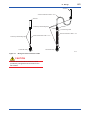
6-3
<6. Wiring>
Antenna
Antenna extension cable 2: 10 m
Antenna
Protect by self-bonding tape
Arrester
Grounding cable
Antenna extension cable 1: 3 m
Protect by self-bonding tape
Antenna extension cable 1: 3 m
Transmitter body
Transmitter body
F0604.ai
Figure 6.4
Wiring the antenna extension cable
CAUTION
Use the dedicated antenna extension cable
provided by Yokogawa as accessories for the
transmitters.
IM 01C27C01-01EN
<6. Wiring>
6-4
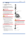
6.1.2.3 Mounting of Arrester and Wiring
6.2 Grounding
Mount an arrester between the extension cables
and connect the grounding cable to the grounding
terminal of the arrester as required.
When using the antenna extension cable with an
arrestor, Class C grounding with the grounding
resistance of 10 Ω is required. Always ground the
transmitter case in accordance with national and
local electrical codes. The most effective transmitter
case grounding method is a direct connection to
earth ground with minimal impedance.
Connect the grounding cable to the grounding
terminal on the transmitter body. Class C grounding
with the grounding resistance of 10 Ω or less is
necessary. Do not share the ground with other
devices.
Antenna side
CAUTION
Grounding is recommended for safe operation.
Antenna extension cable 2
Grounding cable
Ground terminal
F0607.ai
Arrester
Figure 6.7
Ground Terminal
Antenna extension cable 1
Transmitter side
Figure 6.5
F0605.ai
Connection of the arrester and antenna
extension cable
Antenna side
Protect by self-bonding tape
Grounding cable
Transmitter side
Figure 6.6
F0606.ai
Arrester protection by self-bonding
tape
IM 01C27C01-01EN
7.
7-1
<7. Operation>
Operation
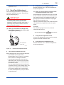
7.1 Preparation for Starting
Operation
Open Tank
The EJX210B flange mounted differential pressure
transmitter measures the levels or densities of
liquids. This section describes the operation
procedure for the EJX210B as shown in Figure 7.1
when measuring a liquid level in an open tank.
NOTE
It is required to set security and network
information to enable the transmitter to be
connected to the Field Wireless Network. For
more details, refer to section 7.4 “Connecting to
the Field Wireless Network”.
(a) Confirm that there is no leak in the connecting
part of the transmitter mounting flange.
Remove the plastic dust cap placed in the
process connector (low pressure side).
(b) Insert batteries into the battery case, and install
to the transmitter. To insert batteries into the
battery case, be careful to polarity of batteries
and battery case. For details of Installation of
battery, refer to section 9.4.6 and 9.4.7.
Battery case is installed in the transmitter when
shipped from the factory, however, batteries are
sold separately and not included.
(c) Using the field wireless configuration tool or
the device configuration tool, confirm that
the transmitter is operating properly. Check
parameter values or change the setpoints as
necessary.
Integral Indicator’s indication can be used
to confirm that the transmitter is operating
properly. For details on how to confirm, refer to
subsection 8.4 “Self-Diagnostics.”
ISA100 devices display self-diagnostic information
in an easy-to-understand manner using four
categories (Check function, Maintenance required,
Failure, and Off specification) according to NAMUR
NE107*.
* NAMUR NE107 [ Self-Monitoring and Diagnosis of Field
Devices ]
F0701.ai
Figure 7.1
Liquid Level Measurement
Confirm that transmitter is operating properly
by integral indicator.
• If the transmitter is faulty, an error code is
displayed.
Self-diagnostic error on integral indicator
(Faulity transmitter)
F0702.ai
Figure 7.2
Integral Indicator with Error Code
NOTE
If any of the above errors are indicated on the
display of the integral indicator or the device
configuration tool, refer to subsection 9.5.3 for
corrective action.
■
Verify and Change Transmitter Parameter
Setting and Values
The parameters related to the following items are
minimum required to be set for operation, and set at
factory as specified in order. Confirm or change the
parameters if needed.
IM 01C27C01-01EN
7-2
<7. Operation>
• Measurement range (measurement lower/
upper limit, unit).
7.2 Zero Point Adjustment
After completing preparations for operating the
transmitter, adjust the zero point. There are two
zero point adjusting ways.
IMPORTANT
Do not turn off the power to the transmitter
immediately after performing a zero point
adjustment. Powering off within 30 seconds of
performing this procedure will return the zero
point to its previous setting.
(1) When you can obtain Low Range Value
from actual measured value of 0% (0 kPa,
atmospheric pressure);
■
Using the Device Configuration Tool
Refer to subsection 8.3.11 “Zero Point Adjustment
and Span Adjustment”.
(2) When you cannot obtain Low Range Value
from actual measured value of 0%;
When adjusting the transmitter zero point, the liquid
level in a tank can not be set to the low limit (0%) of
the measuring range; use a digital manometer or a
glass gauge to match the transmitter output signal
with the actual measured value.
Adjust the transmitter output to the actual measured
value obtained by a digital manometer or a glass
gauge.
[Example]
The measuring range of 0m to 2m; the actual
measured value of 0.8m.
Actual measured value=
■
0.8
2
x100=40.0%
Using the Zero-adjustment screw
Turn the zero adjustment screw to match the output
signal to the actual measured value.
■
Zero-adjustment
screw cover
Using the Device Configuration Tool
Refer to subsection 8.3.11 “Zero Point Adjustment
and Span Adjustment”.
F0703.ai
Figure 7.3
■
External Zero Adjustment Screw
Using the Zero-adjustment screw
Before adjusting zero point, make sure followings.
• The External zero trim parameter
(External Zero Trim) is “Trim on”. For details,
refer to section 8 “Setting Parameters”.
• Use a slotted screwdriver to turn the zeroadjustment screw. Turn the screw clockwise
to increase the output or counterclockwise to
decrease the output.
The zero point adjustment can be made with
a resolution of 0.01% of the setting range. The
degree of zero adjustments varies with the
screw turning speed; turn the screw slowly
to make a fine adjustment, quickly to make a
rough adjustment.
IM 01C27C01-01EN
7-3
<7. Operation>
7.3 Starting Operation
After completing the zero point adjustment, follow
the procedure below to start operation.
n
thi
wi
cm
30
1) Confirm the operating status.
2) After confirming the operating status, perform
the following:
IMPORTANT
• Close the terminal box cover and the
amplifier cover. Screw each cover in tightly
until it will not turn further.
• Tighten the zero-adjustment cover mounting
screw to fix the cover in position.
7.4 Connecting to the Field
Wireless Network
■
Preparation work prior to connecting to a
field wireless network
This transmitter does not need to be connected
with a physical wire. Instead of physical wiring, it
is necessary to set the field wireless devices to
communicate with before installing the transmitter.
This procedure is called a provisioning.
This transmitter supports provisioning via infrared
communication using a provisioning device and
can be securely connected to a network. If the
provisioning information is not set, the transmitter
cannot be connected to the field wireless network.
Provisioning:
Provisioning is work to set the security and
network information to enable the transmitter
to be connected to the field wireless network.
This transmitter supports a provisioning method
using infrared communication.
For details on provisioning using a provisioning
device, and procedure for connecting the
transmitter to the Field Wireless Network, refer
to the User’s Manual, FieldMate Versatile Device
Management Wizard (IM 01R01A01-01E),
YFGW710 Field Wireless Integrated Gateway (IM
01W01F01-01EN) and YFGW410 Field Wireless
Management Station (IM 01W02D01-01EN).
F0704.ai
Figure 7.4
■
Provisioning Example
Provisioning work
This subsection describes provisioning work using
FieldMate as the provisioning device.
Provisioning work performs provisioning for each
field wireless device using FieldMate and an
infrared adapter. If use Yokogawa-recommended
infrared device for provisioning, set distance
between the glass window surface to the infrared
device within 30cm.
For details of Yokogawa-recommended infrared
device, refer to subsection 9.2 “Calibration
Instruments Selection”.
Perform the following provisioning tasks.
• Setting provisioning information
• Creating a provisioning information file
1)Setting provisioning information
Set the device tag and network ID using a
FieldMate provisioning function. The device
tag, network ID, and join key are set in the field
wireless device. It is not necessary to input
a join key because FieldMate automatically
generates it.
Setting device tag
The device tag is used for the user to
recognize the field wireless device.
Setting network ID
This is the network ID for the field wireless
network to which the field wireless device is
connected. Set a value from 2 to 65535.
The field wireless device is connected to the
field wireless network corresponding to the
network ID set by provisioning work.
IM 01C27C01-01EN
2)Creating a provisioning information file
The following provisioned information is stored
in the provisioning information file.
• Network ID
• Device tag
• EUI64
• Join key
• Provisioner (name of the user who performed
provisioning work by FieldMate)
• Date (Time and date when provisioning was
performed by FieldMate)
This provisioning information file is required
to load from the field wireless configurator to
the field wireless integrated gateway. Store
the file carefully.
■
Mounting battery pack
Boot
Search failure for
the specified time
Infrared communication
Mounting the battery pack automatically starts a
search for the field wireless network. When the field
wireless integrated gateway is found, the instrument
enters the join status.
When the field wireless integrated gateway is not
found, the search for the field wireless network
continues.
When the field wireless integrated gateway is not
found and a specified time based on the silence
mode has elapsed, a cycle of a one-hour pause and
six-minute search is repeated until the instrument
can join the field wireless network.
For details on the procedure to switch to silence
mode, refer to subsection 8.3.14 “Switching to
Silence Mode.”
NOTE
If the transmitter searches the Field Wireless
Network for long time at low ambient
temperature condition, sometimes error “AL.70
LOWBAT” is displayed on the Integral Indicator.
Even though using new batteries, it can occur. It
occurs because of battery characteristics. After
joining to the Field Wireless Network, this error
will be cleared within one hour if battery has no
failure.
Pause (b)
Infrared
communication
Infrared
communication
Deep sleep (a)
Deep sleep
setting
1 hour
passed
Search failure
for 6 minutes
Ready 1:
Searching (b)
(Disconnect)
(Disconnect)
Ready 2:
Searching (b)
(Connect)
(Connect)
Connecting to a field wireless network
The action after installing the battery pack varies
depending on the silence mode setting.
7-4
<7. Operation>
Operation (d)
Confirm connecting
status: Join (c)
(Publish)
Figure 7.5
F0705.ai
Wireless Connection Process
(a)Deep sleep
F0706.ai
(b)Ready and pause
F0707.ai
IM 01C27C01-01EN
7-5
<7. Operation>
(c)Confirm connecting status
F0708.ai
(d)Join
7.6 Venting or Draining
Transmitter Pressuredetector Section
Since this transmitter is designed to be selfdraining and self-venting with vertical impulse
piping connections, neither draining nor venting
will be required if the impulse piping is configured
appropriately for self-draining or self-venting
operation.
If condensate (or gas) collects in the transmitter
pressure-detector section, the measured pressure
may be in error. If it is not possible to configure the
piping for self-draining (or self-venting) operation,
you will need to loosen the drain (vent) screw on the
transmitter to completely drain (vent) any stagnated
liquid (gas).
After draining (or venting), fasten the drain (vent)
screw on the transmitter.
IMPORTANT
F0709.ai
7.5 Shutting Down The
Transmitter
Remove the battery pack for turn off the power,
or set into Deep Sleep mode by the device
configuration tool.
NOTE
• Whenever shutting down the transmitter for
a long period, detach the transmitter from the
Tank.
• For details on how to remove the battery
pack, refer to subsection 9.4.5 “Replacing
the Battery Pack.”
• When storing the instrument with a battery
pack inserted, it is recommended to put the
instrument into deep sleep mode to conserve
battery power. For details on how to switch to
deep sleep mode, refer to subsection 8.3.13
“Switching to Deep Sleep Mode.”
Draining condensate or bleeding off gas disturbs
the pressure measurement, this should not be
done when the loop is in operation.
7.6.1 Draining Condensate (low pressure
side)
1) Gradually open the drain plug and drain the
transmitter pressure-detector section.
(See Figure 7.6)
2) When all accumulated liquid is completely
removed, close the drain plug.
3) Tighten the drain plug to a torque of 34 to 39
N·m {3.5 to 4 kgf·m}.
WARNING
Since the accumulated liquid (or gas) may be
toxic or otherwise harmful, take appropriate care
to avoid contact with the body, or inhalation of
vapors.
IM 01C27C01-01EN
7-6
<7. Operation>
7.6.3 Draining Condensate for Flushing
Connection Ring
1) Gradually open the drain screw to drain from
the flushing connection ring.
2) When the flushing connection ring is completely
drained, close the drain screw.
3) Tighten the drain screw to a torque of 10 N·m
{1 kgf·m}.
Drain plug
When you loosen the drain screw,
the accumulated liquid(or gas)
will be expelled in the direction of
the arrow.
When you loosen the drain plug, the
accumulated liquid or gas will be expelled
in the direction of the arrow.
F0710.ai
Figure 7.6
Draining the Transmitter
Drain screw
7.6.2 Venting Gas (low pressure side)
1) Gradually open the vent screw to vent gas from
the transmitter pressure-detector section.
(See Figure 7.7)
2) When the transmitter is completely vented,
close the vent screw.
3) Tighten the vent screw to a torque of 10 N·m
{1 kgf·m}.
WARNING
F0712.ai
Figure 7.8
Draining for Flushing Connection Ring
WARNING
Since the accumulated liquid (or gas) may be
toxic or otherwise harmful, take appropriate care
to avoid contact with the body, or inhalation of
vapors.
Since the accumulated liquid (or gas) may be
toxic or otherwise harmful, take appropriate care
to avoid contact with the body, or inhalation of
vapors.
Vent screw
When you loosen the vent screw, the
accumulated liquid or gas will be
expelled in the direction of the arrow.
F0711.ai
Figure 7.7
Venting the Transmitter
IM 01C27C01-01EN
<7. Operation>
7-7
7.6.4 Venting Gas for Flushing Connection
Ring
1) Gradually open the vent screw to vent gas from
the flushing connection ring.
2) When the flushing connection ring is completely
vented, close the vent screw.
3) Tighten the vent screw to a torque of 10 N·m
{1 kgf·m}.
Vent screw
When you loosen the vent screw,
the accumulated liquid(or drain)
will be expelled in the direction
of the arrow.
F0713.ai
Figure 7.9
Venting for Flushing Connection Ring
WARNING
Since the accumulated liquid (or gas) may be
toxic or otherwise harmful, take appropriate care
to avoid contact with the body, or inhalation of
vapors.
IM 01C27C01-01EN
8.
<8. Setting Parameters>
Setting Parameters
This transmitter can remotely handle range
changes, Tag No. setup, monitoring of selfdiagnostic results, and zero-point adjustment, etc.
according to communication with the field wireless
configuration tool or the device configuration tool.
8.1 Environment for parameter
setting
After installing the battery pack, perform
provisioning and have the transmitter join the field
wireless network.
This transmitter supports the OOB (out-of-band)
method using the infrared communication as a
provisioning method.
Refer to Subsection 7.4 “Connecting to the Field
Wireless Network” for details of the provisioning.
Infrared port
F0801.ai
Figure 8.1
8-1
Infrared port of the transmitter
8.2 Preparing Software
8.2.1 Softwares for the Field Wireless
Configuration Tool and the Device
Configuration Tool
Before using the device configuration tool,
confirm that CF/DD and DeviceDTM for your
transmitter (wireless EJX) are installed in the device
configuration tool.
CF/DD and DeviceDTM are provided by the DVDROM attached to the YFGW710 Field Wireless
Integrated Gateway.
Refer to YFGW710 Field Wireless Integrated
Gateway (IM 01W01F01-01EN) for details.
CF (Capabilities File)/DD (Device Description)
A CF contains information, such as the vendor
of the field device, its model and revision,
available types of process data (flow rate,
temperature, pressure, etc.), and number of
data items. A DD file contains the information
on parameters, such as data structures and
attributes.
DeviceDTM
DeviceDTM (Device Type Manager) is driver
software for field devices provided based on the
FDT (Field Device Tool) technology.
The field wireless configuration tool or the device
configuration tool allows confirming the device
information.
Refer to Subsection 9.2 “Calibration Instruments
Selection” for the field wireless configuration
tool or the device configuration tool of our
recommendation.
8.2.2 Software Download
Software download function permits to update
wireless field device software via ISA100.11a
wireless communication. For details, refer to
YFGW710 Field Wireless Integrated Gateway (IM
01W01F01-01EN) or YFGW410 Field Wireless
Management Station (IM 01W02D01-01EN).
IM 01C27C01-01EN
8.3 Setting Parameters
8.3.1 Parameter Usage and Selection
Before setting a parameter, please see the following
table for a summary of how and when each
parameter is used.
Table 8.1
8-2
<8. Setting Parameters>
IMPORTANT
After setting and sending data with the field
wireless configuration tool or the device
configuration tool, wait 30 seconds before
turning off the transmitter. If it is turned off
too soon, the settings will not be stored in the
transmitter.
Parameter Usage and Selection
Item
Tag No
Description
Output
Sets the tag No. as Device Tag (Software Tag). Sixteen characters
(alphanumeric characters, including - and •) can be set.
The process variable and the diagnostic result can be output.
Range
Either or all of differential pressure (AI1:Process Value), static pressure
(AI2:Process Value), temperature(AI3:Process Value) of capsule or
amplifier and self-diagnostic information (UAPMO:Diagnostic Status) can
be set to the output
Adjust the range corresponding for 0% to 100%.
The unit of the range, input value at 0% (LRV) and input value at 100%
(URV) is set.
Note: LRV and URV can be set within the range of -32000 to 32000.
Damping time constant
Output signal and integral indicator mode
Output signal low cut mode
Integral indicator range of scale and unit
Damping time constant is used to reduce the large fluctuation of pressure
signal and given by each Process Value Filter Time parameter for
differential Pressure/pressure (AI1) and Static pressure (AI2).
Sets mode for output signal and integral indicator to “linear mode”
(proportional to input differential pressure) or to “Square root mode”
(proportional to flow).
Used mainly to stabilize output near 0 if output signal is the square root
mode. Two modes are available: forcing output to 0% for input below a
specific value, or changing to proportional output for input below a specific
value.
Sets one of differential pressure/pressure value, static pressure value, or
temperature value for the integral indicator scale.
Note: LRV and URV can be set within the range of -32000 to 32000.
Unit for displayed temperature
Unit for displayed static pressure
Direction of impulse piping connection
(which is high pressure, L side or R side)
Range with actual input applied
Sets a temperature unit to be displayed.
Sets a pressure unit for the static pressure to be displayed
Used where installation conditions makes it imperative to connect high
pressure side impulse line to low pressure side of transmitter.
Normally, correspond by replacing impulse line, and use this function only
when unavoidable.
Range corresponding for 0% to 100% signal is set with actual input
applied.
The output setting can be done just 100% to user’s reference pressure
output.
Zero Point Adjustment and Span Adjustment
However, when shipping it, the calibration is done in high accuracy as for
DPharp. Please do the span setting by a usual range setting.
Handle Zero Point Adjustment and Span Adjustment.
Reset adjustment
Software write protect
Operational mode
There are two methods of Zero Point Adjustment, using external zeroadjustment screw and using the device configuration tool
The amount of the adjustment set by user can be cleared.
Prohibit writing the setting data.
Set the operational mode of the sensor and integral indicator, etc.
Note: Some of the parameter settings are in a dialogue form called method, the on-line instructions you can configure the parameters
easily.
IM 01C27C01-01EN
<8. Setting Parameters>
8-3
8.3.2 Function Block and Menu Tree
(1) Function Block
The function of this transmitter is shown below. A specific function might not be able to be used according to the
field wireless configuration tool used. When the field wireless configuration tool of our recommendation is used,
the software attached to the Field Wireless Integrated Gateway is necessary for setting the dotted line part.
Refer to Subsection 9.2 “Calibration Instruments Selection” for the field wireless configuration tool of our
recommendation.
(a) Integral antenna type (Amplifier housing code: 7)
Online Menu
• UAPMO
• UDO
• CO
• TRANSDUCER
• AI1 DP
• AI2 SP
• AI3 Temp
(UAPMO)
• Configuration
• Diagnostics/Alerts
• Power Status
• Identification
(Configuration)
• UAP Option
• Hardware Write Protect
• Static Revision
• Reset Energy Left
• Radio Silence
(Diagnostics/Alerts)
• Diagnostic Status
• Diagnostic Status Detail1,
Diagnostic Status Detail2
• Diagnostic Switch
• Diagnostic Configuration
(Power Status)
• Energy Left
• Power Supply Status
(Identification)
• Version Revision
• CTS Version
• ITS Version
• Identification Number
(UDO)
• APP Download
(CO)
• Configuration
• Others
(APP Download)
• DESCRIPTION
• STATE
• MAX_BLOCK_SIZE
• LAST_BLOCK_DOWNLOADED
• ERROR_CODE
(Configuration)
• COMM_ENDPOINT
• COMM_CONTRACT
• PUB_ITEM_MAX
• PUB_ITEM_NUM
• PUB_ITEM
(Others)
• REVISION
(TRANSDUCER)
• Block Info
• Configuration/
Calibration
• Others
(COMM_ENDPOINT)
• Network address of remote endpoint
• Transport layer port at remote endpoint
• Object ID at remote endpoint
• Stale data limit
• Data publication period
• Ideal publication phase
• PublishAutoRetransmit
• Configuration status
(COMM_CONTRACT)
• ContractID
• Contract_Status
• Actual_Phase
(PUB_ITEM)
• ObjectID
• AttributeID
• AttributeIndex
• Size
(Block Info)
• Tag Description
(Configuration/Calibration)
• Auto Recovery
• Model
• Sensor Serial Number
• Measurement Rate
• Measurement Mode
• Wireless Status
• Display Selection
• LCD Mode
• Special Order ID
• Unit Sel1
• Display Unit1
• EJX Key
• Test Key 1
• Test Key 2
• Test Key 3
(Others)
• Special Cmd
F0802-1.ai
IM 01C27C01-01EN
8-4
<8. Setting Parameters>
Online Menu (continued)
(AI1 DP)
• Block Info
• Block Mode
• Dynamic Variables
• Configuration
• Calibration
• Others
(Block Info)
• Tag Description
(Block Mode )
• Mode.Target
• Mode.Actual
• Mode.Permitted
• Mode.Normal
(Dynamic Variables)
• Process Value
• Simulation
(Process Value)
• Process Value.Status
• Process Value.Value **
(Simulation)
• Simulate Switch
• Transducer Value
• Simulate Value
(Configuration)
(Block Mode)
• Block Mode
• Concentrator OID
• Scale *
• Process Value Filter Time
• Mode.Target
• Mode.Actual
• Mode.Permitted
• Mode.Normal
(Transducer Value)
• Transducer Value.
Status
• Transducer Value.
Value
(Simulate Value)
• Simulate Value.
Status
• Simulate Value.
Value
(Scale)
• Scale.EU at 100% *
• Scale.EU at 0% *
• Scale.Units Index *
• Scale.Decimal *
(Calibration)
(Block Mode)
• Block Mode
• Cal Cmd *
• Cal Status
• Calibration Highest Point *
• Calibration Lowest Point *
• Calibration Minimum Span
• External Zero Trim *
• Mode.Target
• Mode.Actual
• Mode.Permitted
• Mode.Normal
(Others)
(PV Range)
• Upper Limit
• Lower Limit
• PV Range *
• Linerization Type *
• Flow Constant *
• Lower cutoff
• Low Cut Mode *
• H/L Swap *
• T Zero Cmp *
• Temp Zero *
• Temp Select *
• PV Range.EU at 100% *
• PV Range.EU at 0% *
• PV Range.Units Index *
• PV Range.Decimal *
F0802-2.ai
*: **: When the data of these parameters is rewritten, it is necessary to set the operational mode of the block to O/S (Out of Service).
When the data of these parameters is rewritten, it is necessary to set the operational mode of the block to Manual.
IM 01C27C01-01EN
8-5
<8. Setting Parameters>
Online Menu (continued)
(AI2 SP)
• Block Info
• Block Mode
• Dynamic Variables
• Configuration
• Others
(Block Info)
• Tag Description
(Block Mode )
• Mode.Target
• Mode.Actual
• Mode.Permitted
• Mode.Normal
(Dynamic Variables)
• Process Value
• Simulation
(Process Value)
• Process Value.Status
• Process Value.Value **
(Simulation)
• Simulate Switch
• Transducer Value
• Simulate Value
(Configuration)
(Block Mode)
• Block Mode
• Concentrator OID
• Scale *
• Process Value Filter
Time
• Mode.Target
• Mode.Actual
• Mode.Permitted
• Mode.Normal
(Transducer Value)
• Transducer Value.
Status
• Transducer Value.
Value
(Simulate Value)
• Simulate Value.
Status
• Simulate Value.
Value
(Scale)
• Scale.EU at 100% *
• Scale.EU at 0% *
• Scale.Units Index *
• Scale.Decimal *
(Others)
(PV Range)
• Upper Limit
• Lower Limit
• PV Range *
• Linerization Type *
• Flow Constant *
• Lower cutoff
• Cal Cmd *
• Cal Status
• Calibration Highest
Point *
• Calibration Lowest
Point *
• Calibration Minimum
Span
• Static Pres Type *
• SP Select *
• PV Range.EU at 100% *
• PV Range.EU at 0% *
• PV Range.Units Index *
• PV Range.Decimal *
F0802-3.ai
*: **: When the data of these parameters is rewritten, it is necessary to set the operational mode of the block to O/S (Out of Service).
When the data of these parameters is rewritten, it is necessary to set the operational mode of the block to Manual.
IM 01C27C01-01EN
8-6
<8. Setting Parameters>
Online Menu (continued)
(AI3 Temp)
(Block Info)
• Block Info
• Block Mode
• Dynamic Variables
• Configuration
• Others
• Tag Description
(Block Mode )
• Mode.Target
• Mode.Actual
• Mode.Permitted
• Mode.Normal
(Dynamic Variables)
• Process Value
• Simulation
(Process Value)
• Process Value.Status
• Process Value.Value **
(Simulation)
• Simulate Switch
• Transducer Value
• Simulate Value
(Configuration)
• Block Mode
• Concentrator OID
• Scale *
• Process Value Filter Time
(Block Mode)
• Mode.Target
• Mode.Actual
• Mode.Permitted
• Mode.Normal
(Transducer Value)
• Transducer Value.
Status
• Transducer Value.
Value
(Simulate Value)
• Simulate Value.
Status
• Simulate Value.
Value
(Scale)
• Scale.EU at 100% *
• Scale.EU at 0% *
• Scale.Units Index *
• Scale.Decimal *
(Others)
• Sensor Range
• Tertiary Value Sel *
*: **: (Sensor Range)
• Sensor Range.EU at 100%
• Sensor Range.EU at 0%
• Sensor Range.Units Index **
• Sensor Range.Decimal **
F0802-4.ai
When the data of these parameters is rewritten, it is necessary to set the operational mode of the block to O/S (Out of Service).
When the data of these parameters is rewritten, it is necessary to set the operational mode of the block to Manual.
IM 01C27C01-01EN
8-7
<8. Setting Parameters>
(b) Detachable antenna type (Amplifier housing code: 8 or 9)
Online Menu
• UAPMO
• UDO
• CO
• TRANSDUCER
• AI1 DP
• AI2 SP
• AI3 Temp
(UAPMO)
• Configuration
• Diagnostics
• Alerts
• Power Status
• Identification
(Configuration)
• UAP Option
• Hardware Write Protect
• Static Revision
• Reset Energy Left
• Radio Silence
• Energy Harvest Type
(Diagnostics)
• Diagnostic Status
• Diagnostic Status Detail.1
• Diagnostic Status Detail.2
• Diagnostic Switch
• Diagnostic Configuration
(Power Status)
• Energy Left
• Power Supply Status
• Power Supply Voltage
(Identification)
• Version Revision
• CTS Version
• ITS Version
• Identification Number
(UDO)
• APP Download
(CO)
• Configuration
• Others
(APP Download)
• DESCRIPTION
• STATE
• MAX_BLOCK_SIZE
• LAST_BLOCK_DOWNLOADED
• ERROR_CODE
(Configuration)
• COMM_ENDPOINT
• COMM_CONTRACT
• PUB_ITEM_MAX
• PUB_ITEM_NUM
• PUB_ITEM
(Others)
• REVISION
(TRANSDUCER)
• Block Info
• Configuration/
Calibration
• Others
(Alerts)
• Other Faults Alert
• Faults Non-compliance Alert
• Faults Process Influence Alert
• Simulation Active Alert
• Soft Update Incomplete Alert
• Power Low Alert
• Power Critical Low Alert
• Fault Prediction Alert
• Environmental Conditions Alert
• Outside Sensor Limits Alert
• Out of Service Alert
• Calibration Problem Alert
• Faults Sensor or Actuator Alert
• Faults Electronics Alert
(COMM_ENDPOINT)
• Network address of remote endpoint
• Transport layer port at remote endpoint
• Object ID at remote endpoint
• Stale data limit
• Data publication period
• Ideal publication phase
• PublishAutoRetransmit
• Configuration status
(COMM_CONTRACT)
• ContractID
• Contract_Status
• Actual_Phase
(PUB_ITEM)
• ObjectID
• AttributeID
• AttributeIndex
• Size
(Block Info)
• Tag Description
(Configuration/Calibration)
• Auto Recovery
• Model
• Sensor Serial Number
• Measurement Rate
• Measurement Mode
• Wireless Status
• Display Selection
• LCD Mode
• Special Order ID
• Unit Sel1
• Display Unit1
• LCD Intermittent Time
• XD Filter
• EJX Key
• Test Key 1
• Test Key 2
• Test Key 3
(Others)
• Special Cmd
F0802-5.ai
IM 01C27C01-01EN
8-8
<8. Setting Parameters>
Online Menu (continued)
(AI1 DP)
• Block Info
• Block Mode
• Dynamic Variables
• Configuration
• Calibration
• Others
(Block Info)
• Tag Description
(Block Mode )
• Mode.Target
• Mode.Actual
• Mode.Permitted
• Mode.Normal
(Dynamic Variables)
• Process Value
• Simulation
(Process Value)
• Process Value.Status
• Process Value.Value **
(Simulation)
• Simulate Switch
• Transducer Value
• Simulate Value
(Configuration)
(Block Mode)
• Block Mode
• Concentrator OID
• Scale *
• Process Value Filter Time
• Mode.Target
• Mode.Actual
• Mode.Permitted
• Mode.Normal
(Transducer Value)
• Transducer Value.
Status
• Transducer Value.
Value
(Simulate Value)
• Simulate Value.
Status
• Simulate Value.
Value
(Scale)
• Scale.EU at 100% *
• Scale.EU at 0% *
• Scale.Units Index *
• Scale.Decimal *
(Calibration)
(Block Mode)
• Block Mode
• Cal Cmd *
• Cal Status
• Calibration Highest Point *
• Calibration Lowest Point *
• Calibration Minimum Span
• External Zero Trim *
• Mode.Target
• Mode.Actual
• Mode.Permitted
• Mode.Normal
(Others)
(PV Range)
• Upper Limit
• Lower Limit
• PV Range *
• Linerization Type *
• Flow Constant *
• Lower Cutoff
• Low Cut Mode *
• H/L Swap *
• T Zero Cmp *
• Temp Zero *
• Temp Select *
• PV Range.EU at 100% *
• PV Range.EU at 0% *
• PV Range.Units Index *
• PV Range.Decimal *
F0802-6.ai
*: **: When the data of these parameters is rewritten, it is necessary to set the operational mode of the block to O/S (Out of Service).
When the data of these parameters is rewritten, it is necessary to set the operational mode of the block to Manual.
IM 01C27C01-01EN
8-9
<8. Setting Parameters>
Online Menu (continued)
(AI2 SP)
• Block Info
• Block Mode
• Dynamic Variables
• Configuration
• Others
(Block Info)
• Tag Description
(Block Mode )
• Mode.Target
• Mode.Actual
• Mode.Permitted
• Mode.Normal
(Dynamic Variables)
• Process Value
• Simulation
(Process Value)
• Process Value.Status
• Process Value.Value **
(Simulation)
• Simulate Switch
• Transducer Value
• Simulate Value
(Configuration)
(Block Mode)
• Block Mode
• Concentrator OID
• Scale *
• Process Value Filter
Time
• Mode.Target
• Mode.Actual
• Mode.Permitted
• Mode.Normal
(Transducer Value)
• Transducer Value.
Status
• Transducer Value.
Value
(Simulate Value)
• Simulate Value.
Status
• Simulate Value.
Value
(Scale)
• Scale.EU at 100% *
• Scale.EU at 0% *
• Scale.Units Index *
• Scale.Decimal *
(Others)
(PV Range)
• Upper Limit
• Lower Limit
• PV Range *
• Linerization Type *
• Flow Constant *
• Lower Cutoff
• Cal Cmd *
• Cal Status
• Calibration Highest
Point *
• Calibration Lowest
Point *
• Calibration Minimum
Span
• Static Pres Type *
• SP Select *
• PV Range.EU at 100% *
• PV Range.EU at 0% *
• PV Range.Units Index *
• PV Range.Decimal *
F0802-7.ai
*: **: When the data of these parameters is rewritten, it is necessary to set the operational mode of the block to O/S (Out of Service).
When the data of these parameters is rewritten, it is necessary to set the operational mode of the block to Manual.
IM 01C27C01-01EN
<8. Setting Parameters>
8-10
Online Menu (continued)
(AI3 Temp)
(Block Info)
• Block Info
• Block Mode
• Dynamic Variables
• Configuration
• Others
• Tag Description
(Block Mode )
• Mode.Target
• Mode.Actual
• Mode.Permitted
• Mode.Normal
(Dynamic Variables)
• Process Value
• Simulation
(Process Value)
• Process Value.Status
• Process Value.Value **
(Simulation)
• Simulate Switch
• Transducer Value
• Simulate Value
(Configuration)
• Block Mode
• Concentrator OID
• Scale *
• Process Value Filter Time
(Block Mode)
• Mode.Target
• Mode.Actual
• Mode.Permitted
• Mode.Normal
(Transducer Value)
• Transducer Value.
Status
• Transducer Value.
Value
(Simulate Value)
• Simulate Value.
Status
• Simulate Value.
Value
(Scale)
• Scale.EU at 100% *
• Scale.EU at 0% *
• Scale.Units Index *
• Scale.Decimal *
(Others)
• Sensor Range
• Tertiary Value Sel *
*: **: (Sensor Range)
• Sensor Range.EU at 100%
• Sensor Range.EU at 0%
• Sensor Range.Units Index **
• Sensor Range.Decimal **
F0802-8.ai
When the data of these parameters is rewritten, it is necessary to set the operational mode of the block to O/S (Out of Service).
When the data of these parameters is rewritten, it is necessary to set the operational mode of the block to Manual.
IM 01C27C01-01EN
8-11
<8. Setting Parameters>
(2) Menu Tree
The menu tree of the device configuration tool of our recommendation is shown below. Refer to Subsection 9.2
“Calibration Instruments Selection” for the device configuration tool of our recommendation.
(a) Integral antenna type (Amplifier housing code: 7)
Online Menu
• Device Configuration
• Diagnostic
• Process Variable
(Device Configuration)
• UAPMO
• TRANSDUCER
• AI1 DP
• AI2 SP
• AI3 Temp
(UAPMO)
• Configure/Setup
(Configuration)
• UAP Option
• Hardware Write Protect
• Static Revision
• Reset Energy Left
• Radio Silence
(Identification)
• Version Revision
• CTS Version
• ITS Version
• Identification Number
(TRANSDUCER)
• Configure/Setup
(Block Info)
• Tag Description
(Configuration/Calibration)
• Auto Recovery
• Model
• Sensor Serial Number
• Measurement Rate
• Measurement Mode
• Wireless Status
• Display Selection
• LCD Mode
• Special Order ID
• Unit Sel1
• Display Unit1
• EJX Key
• Test Key 1
• Test Key 2
• Test Key 3
(Others)
• Special Cmd
(AI1 DP)
• Configure/Setup
(Block Info)
• Tag Description
(Block Mode)
• Mode.Target
• Mode.Actual
• Mode.Permitted
• Mode.Normal
(Configuration)
• Block Mode
• Concentrator OID
• Scale *
• Process Value Filter Time
(Calibration)
• Block Mode
• Cal Cmd *
• Cal Status
• Calibration Highest Point *
• Calibration Lowest Point *
• Calibration Minimum Span
• External Zero Trim *
(Others)
• Upper Limit
• Lower Limit
• PV Range *
• Linerization Type *
• Flow Constant *
• Lower cutoff
• Low Cut Mode *
• H/L Swap *
• T Zero Cmp *
• Temp Zero *
• Temp Select *
(Block Mode)
• Mode.Target
• Mode.Actual
• Mode.Permitted
• Mode.Normal
(Scale)
• Scale.EU at 100% *
• Scale.EU at 0% *
• Scale.Units Index *
• Scale.Decimal *
(Block Mode)
• Mode.Target
• Mode.Actual
• Mode.Permitted
• Mode.Normal
(PV Range)
• PV Range.EU at 100% *
• PV Range.EU at 0% *
• PV Range.Units Index *
• PV Range.Decimal*
F0803-1.ai
*: When the data of these parameters is rewritten, it is necessary to set the operational mode of the block to O/S (Out of Service).
IM 01C27C01-01EN
8-12
<8. Setting Parameters>
Online Menu (continued) Device Configuration
(continued)
(AI2 SP)
(Block Info)
• Configure/Setup
• Tag Description
(Block Mode)
• Mode.Target
• Mode.Actual
• Mode.Permitted
• Mode.Normal
(Configuration)
(Block Mode)
• Block Mode
• Concentrator OID
• Scale *
• Process Value Filter Time
• Mode.Target
• Mode.Actual
• Mode.Permitted
• Mode.Normal
(Scale)
• Scale.EU at 100% *
• Scale.EU at 0% *
• Scale.Units Index *
• Scale.Decimal *
(AI3 Temp)
• Configure/Setup
(Others)
(PV Range)
• Upper Limit
• Lower Limit
• PV Range *
• Linerization Type *
• Flow Constant *
• Lower cutoff
• Cal Cmd *
• Cal Status
• Calibration Highest Point *
• Calibration Lowest Point *
• Calibration Minimum Span
• Static Pres Type *
• SP Select *
• PV Range.EU at
100% *
• PV Range.EU at
0% *
• PV Range.Units
Index *
• PV Range.
Decimal *
(Block Info)
• Tag Description
(Block Mode)
• Mode.Target
• Mode.Actual
• Mode.Permitted
• Mode.Normal
(Configuration)
(Block Mode)
• Block Mode
• Concentrator OID
• Scale *
• Process Value Filter Time
• Mode.Target
• Mode.Actual
• Mode.Permitted
• Mode.Normal
(Scale)
• Scale.EU at 100% *
• Scale.EU at 0% *
• Scale.Units Index *
• Scale.Decimal *
(Others)
• Sensor Range
• Tertiary Value Sel *
(Sensor Range)
• Sensor Range.EU
at 100%
• Sensor Range.EU
at 0%
• Sensor Range.Units
Index *
• Sensor Range.
Decimal *
F0803-2.ai
*: When the data of these parameters is rewritten, it is necessary to set the operational mode of the block to O/S (Out of Service).
IM 01C27C01-01EN
<8. Setting Parameters>
8-13
Online Menu (continued)
(Diagnostic)
(UAPMO)
(Diagnostics/Alerts)
• UAPMO
• Device Diagnostics
• Diagnostic Status
• Diagnostic Status Detail1,
• Diagnostic Status Detail2
• Diagnostic Switch
• Diagnostic Configuration
(Power Status)
• Energy Left
• Power Supply Status
(Process Variable)
• AI1 DP
• AI2 SP
• AI3 Temp
(AI1 DP)
• Process Variable
(Dynamic
Variables)
(Process Value)
• Process Value
• Simulation
• Process Value.Status
• Process Value.Value **
(Simulation)
• Simulate Switch
• Transducer Value
• Simulate Value
(Transducer Value)
• Transducer Value.
Status
• Transducer Value.
Value
(Simulate Value)
• Simulate Value.
Status
• Simulate Value.
Value
(AI2 SP)
• Process Variable
(Dynamic
Variables)
(Process Value)
• Process Value
• Simulation
• Process Value.Status
• Process Value.Value **
(Simulation)
• Simulate Switch
• Transducer Value
• Simulate Value
(Transducer Value)
• Transducer Value.
Status
• Transducer Value.
Value
(Simulate Value)
• Simulate Value.
Status
• Simulate Value.
Value
(AI3 Temp)
• Process Variable
(Dynamic
Variables)
(Process Value)
• Process Value
• Simulation
• Process Value.Status
• Process Value.Value **
(Simulation)
• Simulate Switch
• Transducer Value
• Simulate Value
(Transducer Value)
• Transducer Value.
Status
• Transducer Value.
Value
(Simulate Value)
• Simulate Value.
Status
• Simulate Value.
Value
F0803-3.ai
*: When the data of these parameters is rewritten, it is necessary to set the operational mode of the block to O/S (Out of Service).
IM 01C27C01-01EN
8-14
<8. Setting Parameters>
(b) Detachable antenna type (Amplifier housing code: 8 or 9)
Menu (Online)
(Device Configuration)
• Device Configuration • UAPMO
• Diagnostic
• TRANSDUCER
• Process Variable
• AI1 DP
• AI2 SP
• AI3 Temp
(UAPMO)
• Configure/Setup
(Configuration)
• UAP Option
• Hardware Write Protect
• Static Revision
• Reset Energy Left
• Radio Silence
• Energy Harvest Type
(Identification)
• Version Revision
• CTS Version
• ITS Version
• Identification Number
(TRANSDUCER)
• Configure/Setup
(Block Info)
• Tag Description
(Configuration/Calibration)
• Auto Recovery
• Model
• Sensor Serial Number
• Measurement Rate
• Measurement Mode
• Wireless Status
• Display Selection
• LCD Mode
• Special Order ID
• Unit Sel1
• Display Unit1
• LCD Intermittent Time
• XD Filter
• EJX Key
• Test Key 1
• Test Key 2
• Test Key 3
(Alerts)
• Other Faults Alert
• Faults Non-compliance
Alert
• Faults Process Influence
Alert
• Simulation Active Alert
• Soft Update Incomplete
Alert
• Power Low Alert
• Power Critical Low Alert
• Fault Prediction Alert
• Environmental
Conditions Alert
• Outside Sensor Limits
Alert
• Out of Service Alert
• Calibration Problem
Alert
• Faults Sensor or
Actuator Alert
• Faults Electronics Alert
(Others)
• Special Cmd
(AI1 DP)
• Configure/Setup
(Block Info)
• Tag Description
(Block Mode)
• Mode.Target
• Mode.Actual
• Mode.Permitted
• Mode.Normal
(Configuration)
• Block Mode
• Concentrator OID
• Scale *
• Process Value Filter Time
(Calibration)
• Block Mode
• Cal Cmd *
• Cal Status
• Calibration Highest Point
• Set Calibration Highest Point *
• Calibration Lowest Point
• Set Calibration Lowest Point *
• Calibration Minimum Span
• External Zero Trim *
(Others)
• Upper Limit
• Lower Limit
• PV Range *
• Linerization Type *
• Flow Constant *
• Lower Cutoff
• Low Cut Mode *
• H/L Swap *
• T Zero Cmp *
• Temp Zero *
• Temp Select *
*: (Block Mode)
• Mode.Target
• Mode.Actual
• Mode.Permitted
• Mode.Normal
(Scale)
• Scale.EU at 100% *
• Scale.EU at 0% *
• Scale.Units Index *
• Scale.Decimal *
(Block Mode)
• Mode.Target
• Mode.Actual
• Mode.Permitted
• Mode.Normal
(PV Range)
• PV Range.EU at 100% *
• PV Range.EU at 0% *
• PV Range.Units Index *
• PV Range.Decimal*
F0803-4.ai
When the data of these parameters is rewritten, it is necessary to set the operational mode of the block to O/S (Out of Service).
IM 01C27C01-01EN
Menu (Online)
(continued)
8-15
<8. Setting Parameters>
Device Configuration
(continued)
(AI2 SP)
(Block Info)
• Configure/Setup
• Tag Description
(Block Mode)
• Mode.Target
• Mode.Actual
• Mode.Permitted
• Mode.Normal
(Configuration)
(Block Mode)
• Block Mode
• Concentrator OID
• Scale *
• Process Value Filter Time
• Mode.Target
• Mode.Actual
• Mode.Permitted
• Mode.Normal
(Scale)
• Scale.EU at 100% *
• Scale.EU at 0% *
• Scale.Units Index *
• Scale.Decimal *
(AI3 Temp)
• Configure/Setup
(Others)
(PV Range)
• Upper Limit
• Lower Limit
• PV Range *
• Linerization Type *
• Flow Constant *
• Lower Cutoff
• Cal Cmd *
• Cal Status
• Calibration Highest Point
• Set Calibration Highest Point *
• Calibration Lowest Point
• Set Calibration Lowest Point *
• Calibration Minimum Span
• Static Pres Type *
• SP Select *
• PV Range.EU at
100% *
• PV Range.EU at
0% *
• PV Range.Units
Index *
• PV Range.
Decimal *
(Block Info)
• Tag Description
(Block Mode)
• Mode.Target
• Mode.Actual
• Mode.Permitted
• Mode.Normal
(Configuration)
(Block Mode)
• Block Mode
• Concentrator OID
• Scale *
• Process Value Filter Time
• Mode.Target
• Mode.Actual
• Mode.Permitted
• Mode.Normal
(Scale)
• Scale.EU at 100% *
• Scale.EU at 0% *
• Scale.Units Index *
• Scale.Decimal *
(Others)
• Sensor Range
• Tertiary Value Sel *
(Sensor Range)
• Sensor Range.EU
at 100%
• Sensor Range.EU
at 0%
• Sensor Range.Units
Index *
• Sensor Range.
Decimal *
F0803-5.ai
*: When the data of these parameters is rewritten, it is necessary to set the operational mode of the block to O/S (Out of Service).
IM 01C27C01-01EN
8-16
<8. Setting Parameters>
Menu (Online)
(continued)
(Diagnostic)
(UAPMO)
(Diagnostics)
• UAPMO
• Device Diagnostics
• Diagnostic Status
• Diagnostic Status Detail.1
• Diagnostic Status Detail.2
• Diagnostic Switch
• Diagnostic Configuration
(Diagnostic Configuration)
(Power Status)
• Energy Left
• Power Supply Status
• Power Supply Voltage
(Process Variable)
• AI1 DP
• AI2 SP
• AI3 Temp
(AI1 DP)
• Process Variable
• Diagnostic.Other Faults
• Diagnostic.Faults Non-Compliance
• Diagnostic.Faults Process Influence
• Diagnostic.Simulation Active
• Diagnostic.Soft Update Incomplete
• Diagnostic.Power Low
• Diagnostic.Power Critical Low
• Diagnostic.Fault Prediction
• Diagnostic.Environmental Conditions
• Diagnostic.Outside Sensor Limits
• Diagnostic.Out of Service
• Diagnostic.Calibration Problem
• Diagnostic.Faults Sensor or Actuator
• Diagnostic.Faults Electronics
(Dynamic
Variables)
(Process Value)
• Process Value
• Simulation
• Process Value.Status
• Process Value.Value **
(Simulation)
• Simulate Switch
• Transducer Value
• Simulate Value
(Transducer Value)
• Transducer Value.
Status
• Transducer Value.
Value
(Simulate Value)
• Simulate Value.
Status
• Simulate Value.
Value
(AI2 SP)
• Process Variable
(Dynamic
Variables)
(Process Value)
• Process Value
• Simulation
• Process Value.Status
• Process Value.Value **
(Simulation)
• Simulate Switch
• Transducer Value
• Simulate Value
(Transducer Value)
• Transducer Value.
Status
• Transducer Value.
Value
(Simulate Value)
• Simulate Value.
Status
• Simulate Value.
Value
(AI3 Temp)
• Process Variable
(Dynamic
Variables)
(Process Value)
• Process Value
• Simulation
• Process Value.Status
• Process Value.Value **
(Simulation)
• Simulate Switch
• Transducer Value
• Simulate Value
(Transducer Value)
• Transducer Value.
Status
• Transducer Value.
Value
(Simulate Value)
• Simulate Value.
Status
• Simulate Value.
Value
F0803-6.ai
*: When the data of these parameters is rewritten, it is necessary to set the operational mode of the block to O/S (Out of Service).
IM 01C27C01-01EN
8.3.3 Parameters for Wireless
Communication
(1) Network Information
Concentrator object block : Configuration
Allows confirming the network information.
(2) Update Time
CO block : Data publication period
Sets the update time value to 0.5 to 3,600 seconds.
When amplifier housing code 7 is specified, note
that more than one second is available.
When update time is set 0 seconds, the transmitter
is stopped to update process variables by way
of the field wireless network. And the transmitter
continues to measure process variables with
special interval time internally.
(3) Measurement Mode
TRANSDUCER block: Measurement Mode
The setting affects the battery life; it becomes
shorter in the continuous mode.
When the update period is set to 1 second or less
in intermittent mode, the mode is automatically
switched to continuous mode. When the update
period is 1 second, the mode is continuous mode,
regardless of the measurement mode.
(4) Measurement Rate
TRANSDUCER block:Measurement Rate
Reads the measurement rate value from 0.5 to
3600 seconds. When amplifier housing code 7
is specified, note that the period more than one
second is displayed. The shorter the measurement
period, the shorter the battery life.
(5) Remaining battery life
UAPMO block: Energy Left
The number of days of remaining battery life is
indicated assuming that a transmitter has been
working under ambient temperature condition as
23 degrees Celsius. It takes several days for the
indicated value to be stabiilzed after the power on
and initialization of the remaining battery life.
UAPMO block: Reset Energy Left
8-17
<8. Setting Parameters>
(6) LCD display
The following steps describe how to set LCD
display.
● Integral antenna type (Amplifier housing
code: 7)
1.On/Off of display
When “LCD Intermittent” in LCD Mode is
parameter is selected, the LCD first displays a
set of screens to be shown and then turns off
for a minute, and the display keeps the cycle
repeatedly. Not selecting this parameter turns
the LCD off.
2.On/Off of continuous display mode
When “LCD Continue” in LCD Mode is
selected, the LCD displays for 5 minutes
continuously then transits to the setting in the
LCD Intermittent.
When measurement mode is set as continuous
mode, the LCD displays continuously
regardless of display mode.
When the update time is set to 1 second, the
LCD display stays on regardless of the status in
LCD Mode.
3.On/Off of bar graph
Select “LCD Bargraph ON” in LCD Mode when
the bar graph is required.
● Detachable antenna type (Amplifier housing
code: 8 or 9)
1.On/Off of display
When “Enable” in LCD Mode is selected, the
LCD displays a set of screens to be shown and
turns off for the specified time based on LCD
Intermittent Time, and the display keeps the
cycle repeatedly. Not selecting this parameter
turns the LCD off.
2.On/Off of continuous display mode
When “Enable” is set to LCD Mode and zero is
set to LCD Intermittent Time, the LCD displays
continuously.
3.On/Off of bar graph
Select “LCD Bargraph ON” in LCD Mode when
the bar graph is required.
When the wireless connection process is in the
status of “ready,” “pause,” or “join,” the LCD display
stays on regardless of the status in LCD Mode.
When changing batteries, the remaining battery life
is initialized by Reset Energy Left parameter.
IM 01C27C01-01EN
NOTE
When the device detects AL01 and AL02, the
LCD display stays on regardless of the status
in LCD mode. See Table 9.3 and 9.4 Error
Message Summary for details.
8.3.4 Tag and Device Information
If these are specified when ordering, the designated
Tag No. and device information are set and
shipped. Tag No. and device information can be
checked as follows.
• Procedure to call up the Tag No. and Device
information
- Device Tag ( Software Tag )
This is specified when writing characters (up
to 16 characters) of amplifiers TAG that differ
from characters specified in Tag No.
Refer to section 7.4 “Connection to the Field
Wireless Network” for confirmation.
<8. Setting Parameters>
8-18
8.3.6 Range Change
The range values are factory-set as specified by
the customer. To change the range, follow the steps
below.
The measurement span is determined by the upper
and lower range values. In this method, the upper
and lower range values can be set independently,
and the span changes according to the range limit
values sent to the transmitter.
• Procedure to call up the PV Range display
AI1, AI2 block: PV Range
Select the AI1 block for the differential pressure
and the AI2 block for the static pressure, then
select “EU at 0%” and “EU at 100%” displayed
in the PV Range parameters, and input the
lower range and upper range values for the
range, respectively.
- Tag Description
This is a universal parameter to store the
comment that describes the content of the
tag located in the TRANSDUCER and AI
blocks.
The AI1, AI2, and AI3 blocks of the AI blocks
correspond to the differential pressure, static
pressure, and temperature, respectively.
• When changing the device information, input
the information based on the following limitation
on the number of characters.
- Message function (up to 32 characters)
TRANSDUCER block:Tag Description
AI1-AI3 block: Tag Description
8.3.5 Unit
The unit parameter is set at the factory before
shipment if specified at the time of order. Follow the
procedure below to change the unit parameter.
• Procedure to call up the Unit Index display
(Units Index)
AI1-AI3 block: Scale.Units Index
To change the Unit display, choose desired
unit among the list of displayed unit selecting
AI1 block as for the differential pressure, AI2
as for the static pressure and AI3 block as for
temperature in the AI blocks.
IM 01C27C01-01EN
8-19
<8. Setting Parameters>
8.3.7 Output Signal Low Cut Mode Setup
8.3.8 Integral Indicator Setup
Low cut mode can be used to stabilize the output
signal near the zero point.
( There is 10% of hysteresis at only point of
transition from low to high)
The following three displays are available for
the Integral Indicator: differential pressure, static
pressure, and temperature.
The following three variables can be displayed on
the integral indicator: % of differential pressure
range, % of static pressure range, and % of
temperature range.
[Setup Low Cut Value]
• Procedure to call up the Lower cutoff* display
AI1 block: Lower cutoff*
Example: setup LOW_CUT of output to 15%
Available displays
% of range
(PRES %)
Lower cutoff*
= (“Eu at 100%” - “Eu at 0%”) × 0.15 + “Eu at 0%”
*: “Low Cutoff” is used instead of “Lower cutoff” for
Detachable antenna type (Amplifier housing code: 8 or
9).
[Setup Low Cut Mode]
• Procedure to call up the Low Cut Mode display
AI1 block: Low Cut Mode
Example: Low cut at 20%
For low cut in Linear mode
(%)
50
Example:
Low cut 20%
0
Input
20
50 (%)
0
Example:
Low cut 20%
Input
50 (%)
F0804.ai
Figure 8.2
Low Cut Mode
The low cut point has hysterisis so that the output
around the point is behaved as below figure.
<Example>
Output mode: Linear
Low cut mode: Zero
Low cut: 20.00%
Low
cut
point
Output
Input
Setting range:
0 to 20%
SP %
52.6 %
Available for differential pressure transmitter.
Follow the procedure described in (1) to (2) below
to set the integral indicator.
(1) Display Selection
Display set to Display Selection is displayed on the
integral indicator.
• Procedure to call up the Display Selection
display
TRANSDUCER block: Display Selection
The Display Selection parameter enables the
differential pressure (AI1 block), static pressure
(AI2 block), and temperature (AI3 block) to be
displayed on the LCD. Select whether or not to
enable each block to be displayed.
(2) Cyclic Display
(20%)
0%
% of static pressure Indicates input static pressure in
(SP %) *1
–10 to 110% range depending on
the set range (SP LRV and SP
URV).
*1:
Output
Output
20
PRES %45.6 %
For low cut in Zero mode
(%)
50
Description
and related parameters
Indicates input pressure in –10 to
110% range depending on the set
range (LRV and URV).
2%
Hystrersis fixed at 10%
of the cut point
Information in the AI1 to AI3 blocks can be
displayed cyclically according to the display On/Off
setting for the differential pressure (AI1 block), static
pressure (AI2 block), and temperature (AI3 block)
selected in the Display Selection parameter.
F0805.ai
IM 01C27C01-01EN
8.3.9 Unit for Displayed Temperature
When the instrument is shipped, the temperature
units are set to C (Centigrade). Follow the
procedure below to change this setting.
• Procedure to call up the Sensor Range.Units
Index display
AI3 block : Sensor Range.Units Index
Confirm that °C(deg C) is selected in the
Sensor Range.Units Index parameter for the
temperature
(AI3 block).
Note: When the unit is changed by Sensor Range.Units Index
parameter in temperature ( Al3 block) , units of capsule
temperature is also changed.
8.3.10 Unit for Displayed Static Pressure
Follow the procedure to change the static pressure
unit.
Changing this parameter also changes the unit for
the static pressure display.
• Procedure to call up the PV Range.Units Index
display
AI2 block : PV Range.Units Index
Confirm that KPa is selected in the PV Range.
Units Index parameter for the static pressure
(AI2 block).
Monitoring the high or low static pressure of the
capsule depends on the setting of parameter
‘SP Select.’
• Procedure to call up the SP Select display
AI2 block: SP Select
Select High or Low in the SP Select parameter
for the static pressure (AI2 block).
Type of static pressure is set Absolute pressure
(Abs) at shipment.
When changing monitoring type of static pressure,
Follow below procedure.
• Procedure to call up the Static Press Type
display
AI2 block: Static Press Type
Select gauge pressure (Gauge) or absolute
pressure (Abs) in the Static Press Type
parameter for the static pressure (AI2 block).
8-20
<8. Setting Parameters>
8.3.11 Zero Point Adjustment and Span
Adjustment
Each EJX-B Series Differential Pressure/Pressure
Transmitter is characterized by factory. But there
are some errors caused by environment and
installed posture.
There are Zero and Span Adjustments to fine-tune
those errors.
Zero Adjustment is adjustment for one point to
adjust the bottom value of the measurement range
as 0 % of output.
The Span Adjustment defines input and output
characteristic between two points that’s one side
assumed as standard.
This is used when there is doubt of span drift or
when it is impossible to make zero at absolute
pressure with adjustment for user’s pressure
standard.
(1) Zero Point Adjustment
a. To set 0% at current input, perform
following procedure.
This method is used only when the pressure at
bottom of measurement range is zero.
• Procedure to call up the low limit adjustment
parameter (Calibration Lowest Point).
AI1 block : Calibration Lowest Point
Set 0 to the Calibration Lowest Point
parameter of differential pressure (AI1 block).
• Procedure to call up the calibration
adjustment parameter (Cal Cmd).
AI1 block : Cal Cmd : CAL_LOW
Lower limit is changed by using Cal Cmd
parameter for differential pressure (Al1
block).
• Procedure to call up the calibration status
parameter (Cal Status).
AI1 block : Cal Status
Confirm the value of CAL_SUCCESS (1)
using the Cal Status parameter.
IM 01C27C01-01EN
<8. Setting Parameters>
b. To match current input and output value,
follow procedure
Like tank level measurement that is
impossible to set actual level to zero, output
value is adjustment to actual level by other
measurement using glass gauge.
This is an adjustment procedure example.
Conditions are as follows, measurement span
is 0 kPa to 25.00kPa, current level is 13.50kPa,
current output is 13.83kPa.
• Procedure to call up the lower limit
adjustment parameter (Calibration Lowest
Point).
AI1 block : Calibration Lowest Point
Set the actual level value of 13.50 kPa to the
Calibration Lowest Point parameter for the
differential pressure (AI1 block). Apply an
actual input and confirm the value specified
in Calibration Lowest Point as the output
value.
8-21
c. Using External Zero-adjustment Screw
External Zero-adjustment parameter (External
Zero Trim) can set permission or prohibition to
adjustment by External Zero-adjustment Screw.
Set “Trim on” to use the External Zeroadjustment Screw. (“Trim on” at shipment)
Use a slotted screwdriver to turn the zero
adjustment screw. Turn the screw clockwise
to increase the output or counterclockwise to
decrease the output. The zero point adjustment
can be made with a resolution of 0.01% of the
setting range.
The degree of zero adjustments varies with
the screw turning speed; turn the screw slowly
to make a fine adjustment, quickly to make a
rough adjustment.
• Procedure to call up the calibration
adjustment parameter (Cal Cmd).
AI1 block : Cal Cmd : CAL_LOW
The present output is changed from 13.83
kPa to 13.50 kPa in CAL_LOW of the
differential pressure (AI1 block) Cal Cmd
parameter.
• Procedure to call up the calibration status
parameter (Cal Status).
AI1 block : Cal Status
Zero-adjustment Screw
F0807.ai
Figure 8.4
Zero-adjustment Screw
Confirm the value of CAL_SUCCESS (1)
using the Cal Status parameter.
DPharp span: 0~25.00 kPa
Actual level: 13.50 kPa
Transmitter output: 13.83 kPa
25.00 kPa
Actual level
13.50 kPa
0.00 kPa
DPharp
F0806.ai
Figure 8.3
Tank level measurement
IM 01C27C01-01EN
(2) Span Adjustment
Span Adjustment is function to change the
input and output characteristic that assumed
the bottom value (zero point) of measurement
range as a standard.
Therefore, perform span adjustment
(adjustment of the upper limit value) after zero
adjustment (adjustment of bottom limit value).
After adding the pressure at point of adjustment
and setting pressure value as parameter, the
transmitter calculates quantity of adjustment
and performs adjustment automatically.
• Procedure to call up the lower limit value
parameter (Calibration Lowest Point).
AI1 block : Calibration Lowest Point
Set the lower limit adjustment value on the
differential pressure (AI1 block) Calibration
Lowest Point parameter screen. Apply a
reference pressure corresponding to the
lower limit of the measurement range to the
differential pressure/pressure transmitter
and set the reference pressure when it has
stabilized.
• Procedure to call up the calibration
adjustment parameter (Cal Cmd).
AI1 block : Cal Cmd : CAL_LOW
Set the lower limit of the measurement range
in CAL_LOW of the differential pressure
(AI1 block) Cal Cmd parameter.
• Procedure to call up the calibration status
parameter (Cal Status).
AI1 block : Cal Status
Confirm the value of CAL_SUCCESS (1)
using the Cal Status parameter.
• Procedure to call up the upper limit
adjustment parameter (Calibration Highest
Point).
AI1 block : Calibration Highest PointI
Set the upper limit adjustment value for the
differential pressure (AI1 block) Calibration
Highest PointI parameter. Apply a reference
pressure corresponding to the upper limit of
the measurement range to the differential
pressure/pressure transmitter and set the
reference pressure when it has stabilized.
8-22
<8. Setting Parameters>
• Procedure to call up the calibration
adjustment parameter (Cal Cmd).
AI1 block: Cal Cmd: CAL_HIGH
Set the upper limit of the measurement range
in CAL_HIGH of the differential pressure (AI1
block) Cal Cmd parameter.
• Procedure to call up the calibration status
parameter (Cal Status).
AI1 block: Cal Status
Confirm the value of CAL_SUCCESS (1)
using the Cal Status parameter.
(3) Adjustments for Static Pressure
For the EJX differential transmitters, zero point
and span adjustments of static pressure is
performed in the same way as with the primary
process variable (PV).
Adjustment should be performed using the
static pressure (AI2 block) Cal Cmd parameter.
After calibration, confirm the status by using the
static pressure (AI2 block) Cal Status.
• Procedure to call up the calibration
adjustment parameter (Cal Cmd).
AI2 block : Cal Cmd
Perform differential pressure zero/span
adjustment before static pressure zero/span
adjustment.
(4) Reset Adjustment
Reset Adjustment clear the amount of
adjustment. Reset Ajustment can be performed
using CAL_CLEAR of the differential pressure
(AI1 block) Cal Cmd parameter for the input
pressure and using CAL_CLEAR of the static
pressure (AI2 block) Cal Cmd parameter for the
static pressure. After Reset Adjustment, confirm
the status by using Cal Status of the cleared
block. The amount of adjustment made by the
external zero-adjustment screw can be reset to
the initial setting as well.
• Procedure to call up the calibration
adjustment parameter (Cal Cmd).
AI1, AI2 block : Cal Cmd : CAL_CLEAR
IM 01C27C01-01EN
8-23
<8. Setting Parameters>
8.3.12 Software Write Protection
Hardware write protection and software write
protection functions are available for this
transmitter.
• Procedure to call up the protection setting
parameter (UAP Option)
UAPMO block : UAP Option
The following settings can be configured in the
UAP Option parameter.
- Setting to enable or disable changing
the setting to the Diagnostic Switch and
Diagnostic Configuration parameters.
- Setting to enable or disable the hardware
write protection switch.
- Setting to enable or disable software write
protection.
• Procedure to call up the protection setting
display parameter (Hardware Write Protect)
UAPMO block : Hardware Write Protect
The Hardware Write Protect parameter enables
the switch status of hardware write protection to
be displayed.
For the relationship between hardware write
protection and software write protection, refer to
section 10. “Parameter Summary”.
8.3.13 Switching to Deep Sleep Mode
When the instrument will not be used for a long
time, switch the instrument to deep sleep mode to
conserve battery power. To switch to deep sleep
mode, follow the procedure below.
• Procedure to call up the switch-to-deep-sleep
parameter
TRANSDUCER block : Special Cmd
Set Deep Sleep mode(Standby) to the Special
Cmd parameter for the TRANSDUCER
block. To start from deep sleep mode, either
remove and insert the battery pack, or use
the provisioning device tool or the device
configuration tool via infrared communication.
CAUTION
After setting the deep sleep mode by infrared
device configuration tool, keep the infrared port
of device away from any other infrared signals.
NOTE
• Transmitter becomes the stop state after
setting deep sleep mode and cannot reply
any request from the device configuration
tool via wireless communication.
• For this reason, there is the case that an
error is display on the device communication
tool via wireless communication.
• To wake up from deep sleep mode, please
pull battery pack and wait more than 30
seconds before attaching battery pack.
8.3.14 Switching to Silence Mode
This is a function to pause the instrument when
it cannot join the field wireless network after a
specified time has elapsed. This function is effective
in conserving battery power when, for example, the
installation of the field wireless integrated gateway
is delayed compared to that of field wireless
devices. The default value is 28800 seconds (8
hours). Thereafter, a cycle of a one-hour pause and
six-minute search is repeated until the instrument
can join the field wireless network.
• Procedure to call up the switch-to-silence
parameter (Radio Silence)
UAPMO block : Radio Silence
Set 0 to 231 seconds for the Radio Silence
parameter of the UAPMO block. If 0 is set, the
Radio Silence parameter is invalid. To start
from silence mode, either remove and insert
the battery pack, or use the provisioning device
tool or the device configuration tool via infrared
communication.
IM 01C27C01-01EN
<8. Setting Parameters>
8.4 Self-Diagnostics
UAPMO block: Diagnostic Status
8.4.1 Identify Problems by Using the
Device Configuration Tool
First, check Diagnostic Status of the self-diagnostic
result.
Table 8.3
Bits
Bit31 (MSB)
Bit30
Bit29
Bit28
Bit27
Bit26
Bit25
Bit24
Bit23
Bit22
Bit21
Bit20
Bit19
Bit18
Bit17
Bit16**
Bit15**
Bit14**
Bit13-Bit08
Bit07-Bit01
Bit00
8-24
Any of the four categories (Check function,
Maintenance required, Failure, and Off
specification) according to NAMUR NE107* is
supplied to Diagnostic Status of each diagnostic
result.
Diagnostic Status
Example
NAMUR NE107
Categorization
Contents
F: Failure status
C: Function check status
O: Out of specification status
M: Maintenance required status
Faults in electronics
Faults in sensor or actuator element
Installation, calibration problem
Out of service
Outside sensor limits
Environmental conditions out of device specification
Fault prediction: Maintenance required
Power is critical low: maintenance need short-term
Power is low: maintenance need mid-term
Software update incomplete
Simulation is active
Faults due to process influence
Faults due to non-compliance with specified operating conditions
Other faults
reserved by WCI
vendor specific area
Detail information available
1: available
0: no available
Checking the Diagnostic Status category allows
taking the proper action. The Diagnostic Status
contents are common for all ISA devices, and the
setting for the Diagnostic Status category can be
changed. For further details, refer to Diagnostic
Status Detail.
In Diagnostic Status Contents that can be
diagnosed by the EJX, the alert category set in Out
of Service can be changed to Check function. To do
so, follow one of the procedures below.
a)UAPMO block: UAP Option, select enable.
b)UAPMO block: Diagnostic Configuration,
change Out of Service from Failure to Check
function.
c)UAPMO block: UAP Option, select disable.
--------F
F
C
C
O
O
M
M
M
C
C
F
F
F
-------
The contents of diagnostic status are defined either
valid or invalid at Diagnostic Switch parameter.
Follow the example below to change “Out of
Service” to invalid.
a)UAPMO block: UAP Option, select enable.
b)UAPMO block: Diagnostic Switch, turn ON
Turn off “Out of Service”. Out of Service.
c)UAPMO block: UAP Option, select disable.
Note: Be careful when changing the alert category and turning
detection on and off as described above. Be sure to set
UAP OPTION to disable again to prevent setting errors.
*: NAMUR NE107 “Self-Monitoring and Diagnosis of
Field Devices”
In Diagnostic Configuration setting, select one from the
followings; F: Failure status, C: Function check status,
O: Out of specification status, or M: Maintenance
required status.
**: Applicable for Detachable antenna type (Amplifier
housing code: 8 or 9).
IM 01C27C01-01EN
<8. Setting Parameters>
8-25
8.4.2 Alert Report
EJX generates alert information related to
Diagnostic Status and automatically sends to a field
wireless gateway. To use this function, the following
alert setting is necessary. When “Out of Service” for
Diagnostic Status alert is required, choose “FALSE”
for [Out of Service.Alert Disable] in the UAPMO
block. Refer to the field wireless gateway User’s
Manual for the setting procedure to obtain the alert
information from the gateway.
The alert report consists of the list of parameter
names as shown Table 8.4 below.
Table 8.4
Contents of Alert Report
Parameter name
Description
DetectObjectTLPort Alert detection port UAP (0xF0B2)
fixed
DetectObject
Alert detection block UAPMO (1)
fixed
DetectTime
Time stamp
AlertDirection
1: generated, 0: clear
AlertPriority
Alert priorities set by users
AlertType
Alert types, see 8.4 SelfDiagnostics
AlertValue
NAMUR107 category
0:Failure, 1:checkFunction,
2:OffSpec, 3:MaintenaceRequired
CAUTION
For a wireless gateway which does not support
the alert report function, the alert setting in
UAPMO block for the transmitter must be set
to “Disable.” Note that YFGW710 field wireless
integrated gateway does not have the alert
report function.
IM 01C27C01-01EN
Table 8.5
8-26
<8. Setting Parameters>
Diagnostic Results Summary
Diagnostic Status
Contents
Faults in electronics
Faults in sensor or actuator
element
Installation, calibration
problem
Out of service
Outside sensor limits
Alert
Type
78
77
76
75
74
NAMUR
NE107
Category
F
F
C
O
C
Environmental conditions
out of device specification.
73
O
Power is critical low:
maintenance need shortterm.
71
M
Power is low:
70
maintenance need mid-term
M
Simulation is active
C
68
Diagnostic Status Detail
Description
AMP_T_SENSOR_FAIL*
Amplifier temperature sensor failure
AMP_EEPROM_FAIL
Amplifier EEPROM failure
AMP_EEP_IRREGULAR
AMP EEPROM version not correct
G_A_COMM_FAIL
G/A failure
FC_DELTA_T_FAIL
C-side delta T circuit failure
FR_DELTA_T_FAIL
R-side delta T circuit failure
WL_AD_FAIL
Battery voltage not detected (AMP
failure)
FC_SENSOR_FAIL
C sensor frequency failure
FR_SENSOR_FAIL
R sensor frequency failure
CAP_T_SENSOR_FAIL
Capsule temperature sensor failure
CAP_EEPROM_FAIL
Capsule EEPROM failure
CAP_EEP_IRREGULAR
CAP EEPROM version not correct
FC_UNOSC_FAIL
C sensor oscillation stop failure
FR_UNOSC_FAIL
R sensor oscillation stop failure
DP_TRIM_SPAN_OUTSIDE
"Pressure span adjustment variable
outside of range"
DP_TRIM_ZERO_OUTSIDE
"Pressure zero adjustment variable
outside of range"
SP_TRIM_SPAN_OUTSIDE
"Static pressure span adjustment
variable outside of range"
SP_TRIM_ZERO_OUTSIDE
"Static pressure zero adjustment
variable outside of range"
LCD_OUTSIDE_LIMIT
LCD display outside of limits
AI1_OUT_OF_SERVICE
AI1 O/S mode
AI2_OUT_OF_SERVICE
AI2 O/S mode
AI3_OUT_OF_SERVICE
AI3 O/S mode
DP_OUTSIDE_LIMIT
Pressure outside of range
SP_OUTSIDE_LIMIT
Static pressure outside of range
CAPT_OUTSIDE_LIMIT
Capsule temperature outside of range
AMPT_OUTSIDE_LIMIT
Amplifier temperature outside of range
DP_OUTSIDE_RANGE
Pressure setting outside of range
SP_OUTSIDE_RANGE
Static pressure setting outside of
range
WL_DEEPSLP_ALM *
Deep sleep due to low battery
CRITICAL_LOWBAT **
Deep sleep due to low battery
WL_LOWBAT_ALM
Low battery
AI1_SIMULATION_ACTIVE
AI1 Simulation mode
AI2_SIMULATION_ACTIVE
AI2 Simulation mode
AI3_SIMULATION_ACTIVE
AI3 Simulation mode
Not applicable for the diagnostic regarding AI2 object and static pressure measurement.
*:
Applicable for Integral antenna type (Amplifier housing code: 7).
**:
Applicable for Detachable antenna type (Amplifier housing code: 8 or 9).
IM 01C27C01-01EN
<8. Setting Parameters>
8-27
8.4.3 Checking with Integral Indicator
NOTE
If an error is detected by running self-diagnostics,
an error number is displayed on the integral
indicator. If there is more than one error, the error
number changes at three-second intervals. See
Table 9.3 regarding the error codes.
F0808.ai
Figure 8.5
Integral Indicator
IM 01C27C01-01EN
9.
9-1
<9. Maintenance>
Maintenance
9.1 Overview
WARNING
Since the accumulated process fluid may be
toxic or otherwise harmful, take appropriate care
to avoid contact with the body or inhalation of
vapors when draining condensate or venting gas
from the transmitter pressure-detector section
and even after dismounting the instrument from
the process line for maintenance.
Maintenance of the transmitter is easy due to its
modular construction. This chapter describes the
procedures for calibration, adjustment, and the
disassembly and reassembly procedures required
for component replacement.
Transmitters are precision instruments. Please
carefully and thoroughly read the following sections
for information on how to properly handle them
while performing maintenance.
IMPORTANT
• As a rule, maintenance of this transmitter
should be done in a maintenance room that
has all the necessary tools.
• The CPU assembly, RF assembly, and
Integral indicator contain sensitive parts that
can be damaged by static electricity.
Take precautions such as using a grounded
wrist strap when handling electronic parts or
touching the board circuit patterns. Also be
sure to place the removed CPU assembly,
RF assembly, or Integral indicator into a bag
with an antistatic coating.
9.2 Calibration Instruments
Selection
Table 9.1 lists the instruments that can be used
to calibrate a transmitter. When selecting an
instrument, consider the required accuracy level.
Exercise care when handling these instruments to
ensure they maintain the specified accuracy.
9.3 Calibration
Use the procedure below to check instrument
operation and accuracy during periodic
maintenance or troubleshooting.
1) Insert the battery pack and then perform
provisioning to have the transmitter join the
Field Wireless Network or preparing the infrared
communication for calibration.
2) Set measurement mode to continuous using
the field device configuration tool and the
update period to 1 second using the field
wireless configuration tool.
3) Connect the devices as shown in Figure 9.1
and allow the transmitter to warm up for at least
5 minutes.
IMPORTANT
If the measurement range 0% point is 0 kPa
or shifted in the positive direction (suppressed
zero), the reference pressure should be applied
as shown in the figure.
If the measurement range 0% point is shifted
in the negative direction (elevated zero), the
reference pressure should be applied using a
vacuum pump.
4) Apply reference pressures of 0%, 50%,
and 100% of the measurement range to the
transmitter. Calculate the errors (differences
between the device configuration tool readings
and reference pressures) as the pressure is
increased from 0% to 100% and is decreased
from 100% to 0%, and confirm that the errors
are within the required accuracy.
(Note)When the output mode is set to “Sg root,” apply reference
pressures of 0, 6.25, 25, 56.25, and 100% instead.
5) When the test is finished, reset measurement
mode and update time to the initial value using
the field device configuration tool and the field
wireless configuration tool.
IM 01C27C01-01EN
Table 9.1
Name
Provisioning
device tool
Field wireless
configuration
tool
Digital
manometer
Pressure
generator
Pressure
source
9-2
<9. Maintenance>
Instruments Required for Calibration
Yokogawa-recommended Instrument
• FieldMate (R2.02.01 or later)
• Provisioning Device Tool
• Infrared adapter certified by Yokogawa
Supplier: ACTiSYS,Product name: IrDA InfraRed USB Adaptor
Product number: IR224UN
• Field Wireless Integrated Gateway attached Software
Field Wireless Configurator
Field Wireless Management Tool
• Field Wireless System related Product
Plant Resource Manager (PRM) (R3.05 or later)
• Device Configuration Tool via Wireless Communication
FieldMate(R2.02.01 or later),DeviceFile(R3.01.01 or later)
• Device Configuration Tool via Infrared Communication
FieldMate(R2.03.00 or later),DeviceFile(R3.02.01 or later)
Model MT220 precision digital manometer
1)For 10 kPa class
Accuracy:
±(0.015% of rdg + 0.015% of F.S.) for 0 to 10 kPa
±(0.2% of rdg + 0.1% of F.S.) . . . . . . . . for -10 to 0 kPa
2)For 130 kPa class
Accuracy:±0.02% of rdg . . . . . . . . . . . . . . . . . . . . for 25 to 130 kPa
±5digits . . . . . . . . . . . . . . . . . . . . . . . . . for 0 to 25 kPa
±(0.2% of rdg + 0.1% of F.S.) . . . . . . . . for -80 to 0 kPa
3)For 700 kPa class
Accuracy:±(0.02% of rdg + 3digits) . . . . . . . . . . . . for 100 to 700 kPa
±5 digits . . . . . . . . . . . . . . . . . . . . . . . . . for 0 to 100 kPa
±(0.2% of rdg + 0.1% of F.S.) . . . . . . . . for -80 to 0 kPa
4)For 3000 kPa class
Accuracy: ±(0.02% of rdg + 10 digits) . . . . . . . . . . for 0 to 3000 kPa
±(0.2% of rdg + 0.1% of F.S.) . . . . . . . . for -80 to 0 kPa
5)For 130 kPa abs class
Accuracy:±(0.03% of rdg + 6 digits) . . . . . . . . . . . for 0 to 130 kPa abs
Model MC100 pneumatic pressure standard for 200 kPa {2 kgf/cm2}, 25
kPa {2500 mmH2O}
Accuracy: ±0.05% of F.S.
Dead weight gauge tester 25 kPa {2500 mmH2O}
Accuracy: ±0.03% of setting
Remarks
Select a manometer having
a pressure range close to
that of the transmitter.
Requires air pressure
supply.
Select the one having a
pressure range close to that
of the transmitter.
Prepare the vacuum pump
for negative pressure
ranges.
Model 6919 pressure regulator (pressure pump)
Pressure range: 0 to 133 kPa {1000 mmHg}
Note: The above table contains the instruments capable of performing calibration to the 0.2% level. Since special maintenance and
management procedures involving traceability of each instrument to higher-level standards are required for calibration to the 0.1%
or higher level, there may be difficulties in calibration to this level in the field. For calibration to the 0.1% level, contact Yokogawa
representatives from which the instrument was purchased or the nearest Yokogawa office.
Model MC100
Pressure generator
P
Supply pressure
Digital
manometer
Flange for
calibration
(note)
P
Pressure source
Reference pressure
(note)
For a diaphragm-extended type, prepare a mating
calibration flange to match the diaphragm extension length
and outer diameter.
Low pressure side
open to atmosphere
F0901.ai
Figure 9.1 Instrument Connections
IM 01C27C01-01EN
9.4 Disassembly and
Reassembly
This section describes procedures for disassembly
and reassembly for maintenance and component
replacement.
Table 9.2 Tools for Disassembly and Reassembly
Tool
Phillips
screwdriver
Slotted
screwdriver
Allen wrenches
Quantity
Remarks
1
JIS B4633, No. 2
1
3
CAUTION
Precautions for the intrinsic safe type
transmitters
Intrinsic safe type transmitters must be, as
a rule, removed to a non-hazardous area
for maintenance and be disassembled and
reassembled to the original state. Check and
confirm the insulation when it is reassembled to
the original state.
Check and confirm the insulation when it is
reassembled to the original state.
Refer to section 2.7 “Insulation Resistance and
Dielectric Strength Test” for details of Resistance
Test.
IMPORTANT
• Perform the provisioning when replacing the
RF assembly. Refer to 7.4 Connecting to the
Field Wireless Network for details.
• Replace the batteries and perform the
parameter settings when replacing the CPU
assembly. Refer to 9.4.6 Replacing the
Batteries.
CAUTION
Always remove Battery pack and shut off
pressures before disassembly and assembly.
Use proper tools for all operations.
9-3
<9. Maintenance>
Wrench
Torque wrench
Adjustable
wrench
Socket wrench
Socket driver
Tweezers
1
1
1
1
1
1
JIS B4648
One each, nominal 3,
4 and 2.5 mm Allen
wrenches
Width across flats, 17 mm
Width across flats, 16 mm
Width across flats, 5.5 mm
9.4.1 Replacing the Integral Indicator
This subsection describes the procedure for
replacing an integral indicator. (See figure 9.2)
■
Removing the Integral Indicator
1) Remove the cover.
2) While supporting the integral indicator with one
hand, loosen its two mounting screws.
3) Dismount the integral indicator from the RF
assembly.
When doing this, carefully pull the integral
indicator straight forward so as not to damage
the connector pins between it and the RF
assembly.
■
Attaching the Integral Indicator
1) Align both the integral indicator and RF
assembly connectors and engage them.
2) Insert and tighten the two mounting screws.
3) Replace the cover.
Table 9.2 shows the tools required.
IM 01C27C01-01EN
5) Replace the cover.
Power
cable
9.4.3 Replacing the CPU Assembly
This subsection describes how to replace the CPU
assembly (see Figure 9.2).
Press
Forward
Stud
■
Integral indicator
Boss
CPU assembly
RF assembly
Mounting screw
Zero
adjustment
screw
Zero-adjustment
screw pin
Amplifer cover
F0902.ai
Figure 9.2
Removing and Attaching Integral
indicator, RF assembly and CPU
Assembly
9.4.2 Replacing the RF Assembly
This subsection describes how to replace the RF
assembly (see Figure 9.2).
■
Removing the RF assembly
1) Remove the cover.
2) Remove the integral indicator (refer to
subsection 9.4.1).
3) Remove the two stud bolts by using a socket
driver (width across flats: 5.5 mm).
4) Disconnect the RF assembly from the CPU
assembly. When doing this, carefully pull the RF
assembly straight forward so as not to damage
the connector pins between it and the CPU
assembly.
5) Disconnect the antenna cable that connects the
RF assembly and the antenna.
NOTE
Be careful not to apply excessive force to the
RF assembly and the connector of the antenna
cable when removing it.
■
9-4
<9. Maintenance>
Mounting the RF assembly
1) Connect the antenna cable between the RF
assembly and the antenna.
2) Align both the RF assembly and CPU assembly
connectors and engage them.
3) Tighten the two stud bolts.
4) Mount the integral indicator (refer to subsection
9.4.1).
Removing the CPU assembly
1) Remove the cover.
Remove the integral indicator and the RF
assembly (refer to subsections 9.4.1 and 9.4.2).
2) Turn the zero-adjustment screw to the position
as shown in Figure 9.2.
3) Disconnect the power cable (cable with brown
connector at the end).
When doing this, lightly press the side of the
CPU assembly connector and pull the cable
connector to disengage (see the upper left of
Figure 9.2).
4) Use a socket driver (width across flats, 5.5 mm)
to loosen the two bosses.
5) Carefully pull the CPU assembly straight
forward to remove it.
6) Disconnect the flat cable (cable with white
connector at the end) that connects the CPU
assembly and the capsule.
NOTE
Be careful not to apply excessive force to the
CPU assembly when removing it.
■
Mounting the CPU assembly
1) Connect the flat cable (with white connector)
between the CPU assembly and the capsule.
2) Connect the power cable (with brown
connector) to the CPU assembly.
NOTE
Make certain that the cables do not get pinched
between the case and the edge of the CPU
assembly.
3) Align and engage the zero-adjustment screw
pin with the groove on the bracket on the CPU
assembly. Then insert the CPU assembly
straight onto the post in the amplifier case.
4) Tighten the two bosses. Mount the RF
assembly, and the integral indicator (refer to
subsections 9.4.1 and 9.4.2).
IM 01C27C01-01EN
9-5
<9. Maintenance>
9.4.5 Replacing the Battery Pack
IMPORTANT
Confirm that the zero-adjustment screw pin is
placed properly in the groove on the bracket prior
to tightening the two bosses. If it is not, the zeroadjustment mechanism will be damaged.
5) Replace the cover.
9.4.4 Replacing the Process Connector
Gaskets
This subsection describes process connector
gasket replacement. (See figure 9.3.)
■
Preparation
Initialize the remaining battery life by using the
parameter of Reset Energy Left in UAPMO block.
When the battery power is burned and emptied,
initialize the remaining battery after prompt
replacement of the battery pack.
■
(a) Loosen the two bolts, and remove the process
connectors.
(b) Replace the process connector gaskets.
(c) Remount the process connectors. Tighten the
bolts securely and uniformly to a torque shown
below, and verify that there are no pressure
leaks.
Model
Torque(N·m)
{kgf·m}
Regarding the transmitter with intrinsically safe
approval, the battery pack can be replaced without
removing the device in hazardous area.
Removing
1) Remove the terminal box cover.
2) Loosen the two battery pack mounting screws
(see Figure 9.4).
3) Pull out the Battery pack.
EJX210B
The battery pack mounting
screws cannot be separated
from the battery pack so as
to prevent drop-off.
39 to 49 {4 to 5}
F0904.ai
Figure 9.4
■
Removing the Battery Pack
Remounting
1) Insert the new battery pack lightly.
2) Push the center of the battery pack and insert it
securely.
3) Tighten the two battery pack mounting screws
to a torque of approximately 0.7 N·m.
4) Replace the terminal box cover.
Process connector gasket
Process connector
Bolt
9.4.6 Replacing the Batteries
F0903.ai
Figure 9.3
Removing and Mounting the Process
Connector
The batteries in the battery pack can be replaced.
Batteries are not installed when shipped from the
factory. Assemble the battery pack as follows.
WARNING
Be sure to replace the batteries or disassemble
and assemble the battery pack in a safe location.
Doing so in an explosive area could cause an
explosion.
IM 01C27C01-01EN
CAUTION
WARNING
When replacing the batteries, be sure to replace
the two batteries at the same time and do not
use an old and a new battery together.
■
Disassembling
1) Loosen the two battery case mounting screws
(Figure 9.5).
2) Separate the battery case into two parts.
3) Remove the old batteries.
■
9-6
<9. Maintenance>
Handling the battery pack
The following precautions must be observed
in order to safely and effectively use a battery
pack. Improper use may lead to fluid leakage,
excessive heat, ignition, or explosion.
• Never charge it.
• Do not short-circuit it.
• Do not disassemble, transform, or modify it.
• Do not heat it or throw it into a fire.
• Do not soak it in fresh water or seawater.
Assembling
1) Insert new batteries into the battery case. Be
careful of the orientation of the batteries.
2) Attach the two parts of the battery case to each
other.
3) Tighten the two battery case mounting screws
to a torque of approximately 0.7 N·m.
The battery pack mounting screws
cannot be separated from battery
pack so as to prevent drop-off.
F0905.ai
Figure 9.5
Removing the Battery Pack
9.4.7 Handling Batteries
This battery pack uses two primary lithium/
thionyl chloride batteries. Each battery contains
approximately 5 grams of lithium, for a total of 10
grams in each pack. Under normal conditions,
the battery materials are self-contained and are
not reactive as long as the batteries and the pack
integrity are maintained. Care should be taken to
prevent thermal, electrical or mechanical damage.
Protect the electrode of the battery pack to avoid
rapid electrical discharge. Discharged a battery may
lead to fluid leakage and excessive heat. Batteries
should be stored in a clean and dry area. For
maximum battery life, storage temperature should
not exceed 30°C.
CAUTION
Observe the following precautions for the safe
disposal of batteries.
• Do not incinerate the battery, and do not
expose it to a high temperature of 100°C
or more. This may lead to fluid leakage or
explosion.
• Dispose of the battery according to laws and
regulations.
Use the following dedicated parts for the battery
pack and batteries.
■ Battery Pack
Part number: F9915NQ (with batteries)
Part number: F9915NK (without batteries)
■ Batteries
Part number: F9915NR
Alternatively, Tadiran TL-5930/S batteries may
be purchased and used.
■
Transportation of products containing
lithium batteries:
Batteries used for this transmitter contain
lithium. Primary lithium batteries are regulated
in transportation by the U.S. Department of
Transportation, and are also covered by the
International Air Transport Association (IATA), the
International Civil Aviation Organization (ICAO), and
the European Ground Transportation of Dangerous
Goods (ARD). It is the responsibility of the shipper
to ensure compliance with these or any other local
requirements. Consult current regulations and
IM 01C27C01-01EN
requirements before shipping. When transporting
this transmitter with the battery pack inserted, keep
it in deep sleep mode in order to conserve battery
power. For details on how to switch to deep sleep
mode, refer to subsection 8.3.13 “Switching to Deep
Sleep Mode.”
■
How to replace and dispose of the
batteries:
This is an explanation about the new EU Battery
Directive(DIRECTIVE 2006/66/EC). This directive is
only valid in the EU.
9-7
<9. Maintenance>
9.5 Troubleshooting
If any abnormality appears in the measured values,
use the troubleshooting flow chart below to isolate
and remedy the problem. Since some problems
have complex causes, these flow charts may
not identify all. If you have difficulty isolating or
correcting a problem, contact Yokogawa service
personnel.
9.5.1 Basic Troubleshooting
Batteries are used for this product.
First determine whether the process variable
is actually abnormal or a problem exists in the
measurement system.
When you remove batteries from this product and
dispose them, discard them in accordance with
domestic law concerning disposal.
If the problem is in the measurement system,
isolate the problem and decide what corrective
action to take.
Take a right action on waste batteries, because the
collection system in the EU on waste batteries are
regulated.
This transmitter is equipped with a self-diagnostic
function which will be useful in troubleshooting,
and the transmitter equipped with an integral
indicator will show an alarm code as a result of selfdiagnosis.
See subsection 9.5.3 for the list of alarms.
Battery type: Primary lithium-thionyl chloride battery
CAUTION
The symbol (see above), which is marked on the
batteries, means they shall be sorted out and
collected as ordained in ANNEX II in DIRECTIVE
2006/66/EC.
■
Procedure to remove the batteries safely:
Refer to subsection 9.4.5 “Replacing the Battery
Pack” and subsection 9.4.6 “Replacing the
Batteries.”
IM 01C27C01-01EN
9-8
<9. Maintenance>
9.5.2 Troubleshooting Flowcharts
: Areas where self-diagnostic offers support
Abnormalities appear in measurement.
YES
The following sorts of symptoms indicate that transmitter
may not be operating properly.
Example : • There is no output signal.
• Output signal does not change even though
process variable is known to be varying.
• Output value is inconsistent with value
inferred for process variable.
Is process variable
itself abnormal?
NO
Inspect the
process system.
Measurement system problem
Check display of the error code.
Check self-diagnostics by the device configuration tool.
Isolate problem in
measurement system.
Does the self-diagnostic
indicate problem location?
NO
YES
Does problem exist in
receiving instrument?
NO
Inspect receiver.
Refer to Alarm Message Summary in
Subsection 9.5.3.
Is there any pressure leak?
Environmental conditions
Transmitter itself
Check/correct
environmental conditions.
Check transmitter.
NO
YES
Check/correct operating
conditions.
YES
Fix pressure leaks, paying particular
attention to connections for impulse
piping,pressure-detector section, etc.
Is the Field Wireless Network
setting correct?
Operating conditions
YES
NO
Reconnect to the Field Wireless
Network.
F0906.ai
Figure 9.5.1 Basic Flow and Self-Diagnostics
Contact Yokogawa service personnel.
F0907.ai
IM 01C27C01-01EN
9-9
<9. Maintenance>
Large output error.
Output travels beyond 0% or 100%.
Connect the device configuration tool and check self-diagnostics.
Does the selfdiagnostic indicate problem
location?
NO
NO
NO
YES
NO
Refer to individual model user manuals
and connect piping as appropriate for
the measurement purpose.
Is transmitter
installed where there is
marked variation in
temperature?
NO
Adjust the zero point.
NO
YES
Refer to Alarm Message Summary in
Subsection 9.5.3.
Is impulse piping
connected correctly?
YES
Fix pressure leaks, paying particular
attention to connections for impulse
piping, pressure-detector section, etc.
Is zero point
adjusted correctly?
YES
Does the selfdiagnostic indicate problem
location?
YES
Refer to Alarm Message Summary in
Subsection 9.5.3.
Is there any pressure leak?
Connect the device configuration tool and check self-diagnostics.
YES
Provide lagging and/or cooling, or allow
adequate ventilation.
Contact Yokogawa service personnel.
F0908.ai
Were appropriate
instruments used for
calibration?
YES
NO
Refer to Section 9.2 "Calibration
Instruments Selection".
Is output adjusted correctly?
YES
NO
Adjust the output.
Contact Yokogawa service personnel.
F0909.ai
IM 01C27C01-01EN
<9. Maintenance>
9-10
9.5.3 Errors and Countermeasures
Table 9.3
Integral
indicator
Error Message Summary (Causes and Actions)
Factory
NAMUR
category
Bit
Diagnostic
Status
Diagnostic Status Detail
Cause
FC_SENSOR_FAIL
FR_SENSOR_FAIL
AL. 01
CAP. ERR
F
Bit 26
*2
Faults
in sensor or
actuator
element
FC_UNOSC_FAIL
FR_UNOSC_FAIL
CAP_T_SENSOR_FAIL
CAP_EEPROM_FAIL
CAP_EEP_IRREGULAR
AMP_T_SENSOR_FAIL*3
Pressure sensor
failure
Capsule
temperature
sensor failure
Capsule
EEPROM
memory failure
F
Bit 27
*2
Faults in
electronics
AL. 10
PRESS
AL. 11
ST. PRSS
AL. 12
CAP. TMP
AL. 13
AMP. TMP
O
Bit 23
AMP_EEP_IRREGULAR
FC_DELTA_T_FAIL
FR_DELTA_T_FAIL
G_A_COMM_FAIL
WL_AD_FAIL
DP_OUTSIDE_LIMIT
None
Amplifier
EEPROM failure
Recovers
when returns to
normal.
None
Amplifier failure
None
Pressure
outside of
specified range
SP_OUTSIDE_LIMIT
Static pressure
outside of
specified range
CAPT_OUTSIDE_LMIT
Capsule
temperature
outside of range
(-50 to 130°C)
Recovers when
input pressure
returns within
the range.
Recovers when
static pressure
returns within
the range.
Recovers when
temperature
returns within
the range.
AMPT_OUTSIDE_LIMIT
Amplifier
temperature
outside of range
(-50 to 95°C)
Recovers when
temperature
returns within
the range.
Outside sensor
limits
Action
Replace the
capsule.
Recovers
when returns to
normal.
None
Amplifier
temperature
sensor failure
AMP_EEPROM_FAIL
AL. 02
AMP. ERR
Release/
recovery
conditions
(except
restart)
Recovers only
when AUTO
RECOVER is
ON and within
the range
Recovers only
when AUTO
RECOVER
is ON and
oscillation does
not stop
None
Replace the
amplifier.
Check
the input
pressure.
Check
the input
pressure.
Retain heat
or insulate
so that
temperature
returns within
the specified
range.
Retain heat
or insulate
so that
temperature
returns within
the specified
range.
IM 01C27C01-01EN
Integral
indicator
<9. Maintenance>
Factory
NAMUR
category
Bit
Diagnostic
Status
Diagnostic Status Detail
Cause
DP_TRIM_SPAN_OUTSIDE
Pressure span
adjustment
variable outside
of range
DP_TRIM_ZERO_OUTSIDE
Pressure zero
adjustment
variable outside
of range
SP_TRIM_SPAN_OUTSIDE
Static pressure
span adjustment
variable outside
of range
SP_TRIM_ZERO_OUTSIDE
Static pressure
zero adjustment
variable outside
of range
LCD_OUTSIDE_LIMIT
LCD display
outside of
specified range
DP_OUTSIDE_RANGE
Input pressure
setting outside
of range
SP_OUTSIDE_RANGE
Static pressure
setting outside
of range
WL_DEEPSLP_ALM*3
Low remaining
battery voltage
results in
switching to
deep sleep.
Battery voltage
is the lowest.
Low remaining
battery voltage
AL.53
P. ADJ
C
Bit 25
Installation,
calibration
problem
AL.53
P. ADJ
AL. 55
SP. ADJ
AL. 55
SP. ADJ
C
Bit 25
Installation,
calibration
problem
AL. 79
OV. DISP
AL. 30
RANGE
O
Bit 22
Environmental
conditions out
of device
specification
Bit 20
Power is critical
low:
maintenance
need short term
AL. 31
SP. RNG
AL. 70
LOWBAT
M
AL. 70
LOWBAT
Bit 19
Power is
low:
maintenance
need mid - term
AL. 60
AI OOS
AL. 61
AI OOS
AL. 62
AI OOS
C
Bit 24
CRITICAL_LOWBAT*4
WL_LOWBAT_ALM
AI1_OUT_OF_SERVICE
AI1 block is O/S
mode.
AI2_OUT_OF_SERVICE
AI2 block is O/S
mode.
AI3_OUT_OF_SERVICE
AI3 block is O/S
mode.
O/S
Release/
recovery
conditions
(except
restart)
Recovers
when span
adjustment
variable/point
returns within
the range.
Recovers
when zero
adjustment
variable/point
returns within
the range.
Recovers
when span
adjustment
variable /point
returns within
the range.
Recovers
when zero
adjustment
variable/point
returns within
the range.
Recovers when
display value
returns within
the range.
Recovers when
setting returns
within the
range.
Recovers when
setting returns
within the
range.
9-11
Action
Check
the span
adjustment
variable for
the Pressure.
Check
the zero
adjustment
variable for
the Pressure.
Check
the static
pressure
span
adjustment
variable.
Check
the static
pressure zero
adjustment
variable.
Check the
display
setting.
Check the
input pressure
setting.
Check
the static
pressure
setting.
None
Replace the
batteries.
None
Replace the
batteries.
Returns when
the mode target
of AI1 block is
other than O/S.
Returns when
the mode target
of AI2 block is
other than O/S.
Returns when
the mode target
of AI3 block is
other than O/S.
Set the mode
target to
AUTO.
Set the mode
target to
AUTO.
Set the mode
target to
AUTO.
IM 01C27C01-01EN
Integral
indicator
<9. Maintenance>
Factory
NAMUR
category
Bit
Diagnostic
Status
AL. 63
AI SIM
C
Bit 17
Simulation is
active
AL. 64
AI SIM
AL. 65
AI SIM
*1:
*2: *3: *4: C
Bit 17
Simulation is
active
Diagnostic Status Detail
Cause
SimulationActive
(AI1)
AI1 block is
simulate mode.
SimulationActive
(AI2)
AI2 block is
simulate mode.
SimulationActive
(AI3)
AI3 block is
simulate mode.
Release/
recovery
conditions
(except
restart)
Returns when
the simulate
mode of AI1
block is set
to disable. 1
(Disable)
Returns when
the simulate
mode of AI2
block is set
to disable. 1
(Disable)
Returns when
the simulate
mode of AI3
block is set
to disable. 1
(Disable)
9-12
Action
Check the
simulate
mode of AI1
block.
Check the
simulate
mode of AI2
block.
Check the
simulate
mode of AI3
block.
"Factory NAMUR category” refers to the four categories (C: Check function, M: Maintenance required, F: Failure, and O: Off
specification) according to NAMUR NE107*.
* NAMUR NE107 “Self-Monitoring and Diagnosis of Field Devices”
When the device detects “AL01 CAP.ERR” and “AL02 AMP.ERR”, the LCD display stays on regardless of the status in LCD mode.
Applicable for Integral antenna type (Amplifier housing code: 7).
Applicable for Detachable antenna type (Amplifier housing code: 8 or 9).
IM 01C27C01-01EN
Table 9.4
Error Message Summary (Output Actions)
Factory
Integral
NAMUR
Indicator
category
Bit
Diagnostic
Status
Output actions
Diagnostic Status Detail
FC_SENSOR_FAIL
FR_SENSOR_FAIL
FC_UNOSC_FAIL
FR_UNOSC_FAIL
CAP_T_SENSOR_FAIL
AL. 01
CAP. ERR F
Bit 26
*2
Faults
in sensor or
actuator
element
CAP_EEPROM_FAIL
CAP_EEP_IRREGULAR
AMP_T_SENSOR_FAIL*3
AMP_EEPROM_FAIL
AMP_EEP_IRREGULAR
AL. 02
AMP.ERR F
*2
9-13
<9. Maintenance>
Bit 27
Faults in
electronics
FC_DELTA_T_FAIL
FR_DELTA_T_FAIL
G_A_COMM_FAIL
WL_AD_FAIL
Pressure
Static
Pressure
Capsule
Temp
Value
Output value
(hold value)
Output status
(BAD: Sensor
Failure)
Normal action
Output value
(hold value)
Output status Normal action
(BAD: Sensor
Failure)
Normal action Output value
(calculated in
a normal way)
Output status
(BAD: Sensor
Failure)
Output value Output value Output value
(hold value)
(hold value)
(calculated in
Output status Output status a normal way)
(BAD: Device (BAD: Device Output status
Failure)
Failure)
(BAD: Device
Failure)
Amp
Temp
Value
Normal action
Output value
(calculated in
a normal way)
Output status
(BAD: Device
Failure)
Output value
(calculated in
a normal way)
Normal action Normal action Normal action
Output status
(BAD: Sensor
Failure)
Output value Output value Output value Output value
(hold value) (hold value)
(calculated in *4
Output status Output status a normal way) (hold value)
(BAD: Device (BAD: Device Output status Output status
Failure)
Failure)
(BAD: Device (BAD: Device
Failure)
Failure)
Output value
(hold value)
output status
(BAD: Device
Failure)
Output value
(calculated in
a normal way)
Output status
(BAD: Device
Failure)
Output value
(hold value)
Output status
(BAD: Device Normal action
Failure)
Output value
(calculated in
a normal way)
Output status
(BAD: Device
Failure)
Output value
*4
(hold value)
output status
(BAD: Device
Failure)
Output value
(calculated in
a normal way)
Output status
(BAD: Device
Failure)
IM 01C27C01-01EN
<9. Maintenance>
Factory
Integral
NAMUR
Indicator
category
Bit
Diagnostic
Status
Output actions
Diagnostic Status Detail
DP_OUTSIDE_LIMIT
AL. 10
PRESS
SP_OUTSIDE_LIMIT
AL. 11
ST. PRSS
O
Bit 23
Outside sensor
limits
CAPT_OUTSIDE_LIMIT
AL. 12
CAP. TMP
AMPT_OUTSIDE_LIMIT
AL. 13
AMP. TMP
DP_TRIM_SPAN_
OUTSIDE
AL. 53
P. ADJ
DP_TRIM_ZERO_
OUTSIDE
AL. 53
P. ADJ
C
AL. 55
SP. ADJ
Installation,
Bit 25 calibration
problem
SP_TRIM_SPAN_
OUTSIDE
SP_TRIM_ZERO_
OUTSIDE
AL. 55
SP.ADJ
AL. 79
OV. DISP
9-14
Pressure
Output value
(calculated in
a normal way)
Output status
(UNCERTAIN:
Sensor
Conversion
not Accurate)
Output value
(calculated in
a normal way)
Output status
(UNCERTAIN:
Non Specific)
Output value
(calculated in
a normal way)
Output status
(UNCERTAIN:
Non Specific)
Static
Pressure
Capsule
Temp
Value
Amp
Temp
Value
Output value
(calculated in
a normal way)
Output status
Normal action Normal action
(UNCERTAIN:
Non Specific)
Output value
(calculated in
a normal way)
Output status
(UNCERTAIN:
Sensor
Conversion
not Accurate)
Output value
(calculated in
a normal way)
Output status
(UNCERTAIN:
Non Specific)
Normal action Normal action
Output value
(calculated in
a normal way)
Output status
Normal action
(UNCERTAIN:
Sensor
Conversion
not Accurate)
Output value
(calculated in
a normal way)
Output status
Normal action Normal action Normal action
(UNCERTAIN:
Sensor
Conversion
not Accurate)
Output value
(calculated in
a normal way)
Output status Normal action Normal action Normal action
(UNCERTAIN:
Range Limits
Exceeded)
Output value
(calculated in
a normal way)
Output status Normal action Normal action Normal action
(UNCERTAIN:
Range Limits
Exceeded)
Output value
(calculated in
a normal way)
Normal action Output status Normal action Normal action
(UNCERTAIN:
Range Limits
Exceeded)
Output value
(calculated in
a normal way)
Normal action Output status Normal action Normal action
(UNCERTAIN:
Range Limits
Exceeded)
LCD_OUTSIDE_LIMIT
Normal action Normal action Normal action Normal action
IM 01C27C01-01EN
<9. Maintenance>
Factory
Integral
NAMUR
Indicator
category
AL. 30
RANGE
AL. 31
SP. RNG
O
AL. 70*6
LOWBAT
M
AL. 70*6
LOWBAT
Bit
Diagnostic
Status
Output actions
Diagnostic Status Detail
Environmental DP_OUTSIDE_RANGE
conditions out
Bit 22 of device
SP_OUTSIDE_RANGE
specification
Power is
critical
low:
Bit 20
maintenance
need
short - term
Power is
low:
Bit 19 maintenance
need
mid - term
CRITICAL_LOWBAT*4
Bit 24 O/S
AI3_OUT_OF_SERVICE
AL. 62
AI OOS
*1: *2: *3: *4: *5: *6:
C
Bit 17
Simulation is
active
Capsule
Temp
Value
Amp
Temp
Value
Normal action Normal action Normal action Normal action
Normal action Normal action Normal action Normal action
Normal action Normal action Normal action Normal action
Normal action Normal action Normal action Normal action
AI2_OUT_OF_SERVICE
AL. 63
AI SIM
AL. 64
AI SIM
AL. 65
AI SIM
Static
Pressure
WL_LOWBAT_ALM
AI1_OUT_OF_SERVICE
C
Pressure
WL_DEEPSLP_ALM*3
AL. 60
AI OOS
AL. 61
AI OOS
9-15
SimulationActive
(AI1)
SimulationActive
(AI2)
SimulationActive
(AI3)
Output value
(hold value)
Output status Normal action Normal action
(BAD: Out of
Service)
Output value
(hold value)
Normal action Output status Normal action
(BAD: Out of
Service)
Output value
(hold value)
Normal action Normal action Output status
(BAD: Out of
Service)
Normal action
Normal action
Output value
(hold value)
Output status
(BAD: Out of
Service)
Normal action Normal action Normal action Normal action
Normal action Normal action Normal action Normal action
Normal action Normal action Normal action Normal action
“Factory NAMUR category” refers to the four categories (C: Check function, M: Maintenance required, F: Failure, and O: Off
specification) according to NAMUR NE107*.
* NAMUR NE107 “Self-Monitoring and Diagnosis of Field Devices”
When the device detects “AL01 CAP.ERR” and “AL02 AMP.ERR”, the LCD display stays on regardless of the status in LCD mode.
Applicable for Integral antenna type (Amplifier housing code: 7).
Amplifier temperature value is calculated in a normal way for Detachable antenna type (Amplifier housing code: 8 or 9).
Applicable for Detachable antenna type (Amplifier housing code: 8 or 9).
When the ambient temperature is higher than 60°C, AL.70 may be generated despite the indication of Energy Left shows sufficiently
remained. However, it does not affect the device operation. This is caused by the change of battery inner status with extremely
low power consumption under high temperature environment. It is recommended to set the data updating period to 15 seconds or
shorter.
IM 01C27C01-01EN
10-1
<10. Parameter Summary>
10. Parameter Summary
Table 10.1
Object
ID
1.
UAPMO
block
Parameter
Attribute
Label
ID
1
Version Revision
10
Static Revision
64
65
Identification
Number
CTS Version
66
ITS Version
67
Diagnostic Status
68
UAP Option
Default
value
Description
Indicates the application revision of EJX This revision
when the application software is downloaded.
Indicates the revision level of the fixed parameters of
UAP Used, for example, to check whether parameters
have been change.
Indicates the vender ID, model ID, and revision of the
device.
Indicates the version of the communication stack test
system (CTS).
Indicates the version of the inter operability test system
(ITS).
Indicates the diagnostic results of the device based on
the NAMUR NE107*1 model.
Setting Enable diagnostic status configuration in UAP
Option to Enable allows turning OFF and ON the
display of the diagnostic results for each summary,
and changing Categorize For Categorize at the time of
shipment, refer to tables 8.3 and 10.2.
Allows setting the Diagnostic Status and write protection
of UAP.
Software write protect
1: On, 0: Off
Enable hardware write protect
1: Enable, 0: Disable (default)
Enable diagnostic status configuration
1: Enable, 0: Disable (default)
The following table shows the relationship between the
hardware write protection and software write protection.
Handling
---
R
0
R
---
R
0
R
0
R
---
R
0
W
On
W
Refer to Table
10.2.
W
Refer to Table
10.2.
---
R
Enable
Hardware Software
hardware
Write
write
write
write
protect
protect
protect
protect
Disable
Off or On Off
No
(Writable)
Disable
Off or On On
Yes
(Unwritable)
Enable
Off
Off or On No
(Writable)
Enable
On
Off or On Yes
(Unwritable)
69
Diagnostic
Switch
70
Diagnostic
Configuration
102
103
Diagnostic Status
Detail[2]
Energy Left
104
Reset Energy Left
Allows setting On/Off for each summary of Diagnostic
Status when Enable diagnostic status configuration in
UAP Option is set to Enable.
Allows Categorize for each summary of Diagnostic
Status when Enable diagnostic status configuration in
UAP Option is set to Enable.
Detailed information on Diagnostic Status. For
Categorize at the time of shipment, refer to Table 10.2.
Indicates the number of days of remaining battery life
assuming ambient temperature condition as 23 degrees
Celsius.
The unit is day.
Initialize the remaining battery life (Energy Left) and
reset it as new batteries.
Perform the battery replacement.
0 = Continue (Cancel)
1 = Reset (Initialization)
R
0 (reading value W
is always 0)
IM 01C27C01-01EN
Object
ID
1.
UAPMO
block
(continued)
10-2
<10. Parameter Summary>
Attribute
ID
Label
Default
value
Description
Indicates the predicted battery level and the power
supply method.
0 = external power supply
1 = battery level 75% or more
2 = battery level 25% ~ 75%
3 = battery level 25% or less
Handling
105
Power Supply
Status
R
106
EHType*2
Available to write note into this parameter.
---
W
107
Power Supply
Voltage*2
Indicates the measured power supply voltage (V).
---
R
110
Hardware Write
Protect
Allows recognizing the status of the hardware write
protection switch.
(Switch Off, Switch On)
111
Radio Silence
Repeats a cycle of a 1-hour pause and 6-minute
search if the instrument cannot join the network after a
time specified in Radio Silence has elapsed.
When 0 is set, the Radio Silence is invalid.
28800
W
112
Simulation Active
Alert*2
The On/Off or priority for Simulation Active Alert can
be set.
1.On/Off setting
0 = FALSE, 255 =TRUE
2.Alert report priority: 0 to 15
1. TRUE
2. 15
W
113
Soft Update
incomplete Alert*2
The On/Off or priority for Soft Update incomplete Alert
can be set.
1.On/Off setting
0 = FALSE, 255 =TRUE
2.Alert report priority: 0 to 15
Not available for EJX.
1. TRUE
2. 15
W
114
Power low Alert*2
The On/Off or priority for Power low Alert can be set.
1.On/Off setting
0 = FALSE, 255 =TRUE
2.Alert report priority: 0 to 15
1. TRUE
2. 15
W
115
Power Critical low
Alert*2
The On/Off or priority for Power Critical low Alert can
be set.
1.On/Off setting
0 = FALSE, 255 =TRUE
2.Alert report priority: 0 to 15
1. TRUE
2. 15
W
116
Fault prediction
Alert*2
The On/Off or priority for Fault prediction Alert can be
set.
1.On/Off setting
0 = FALSE, 255 =TRUE
2.Alert report priority: 0 to 15
Not available for EJX.
1. TRUE
2. 15
W
117
Environmental
conditions Alert*2
The On/Off or priority for Environmental conditions
Alert can be set.
1.On/Off setting
0 = FALSE, 255 =TRUE
2.Alert report priority: 0 to 15
1. TRUE
2. 15
W
118
Outside sensor
limits Alert*2
The On/Off or priority for Outside sensor limits Alert
can be set.
1.On/Off setting
0 = FALSE, 255 =TRUE
2.Alert report priority: 0 to 15
1. TRUE
2. 15
W
119
Out of service
Alert*2
The On/Off or priority for Out of service Alert can be
set.
1.On/Off setting
0 = FALSE, 255 =TRUE
2.Alert report priority: 0 to 15
1. TRUE
2. 15
W
120
Callibration
problem Alert*2
The On/Off or priority for callibration problem Alert can
be set.
1.On/Off setting
0 = FALSE, 255 =TRUE
2.Alert report priority: 0 to 15
1. TRUE
2. 15
W
R
IM 01C27C01-01EN
Object
ID
1.
UAPMO
block
(continued)
2.
UDO
block
3.
CO
block
10-3
<10. Parameter Summary>
Attribute
ID
Label
Default
value
Description
Handling
121
Faults Sensor or
actuator Alert*2
The On/Off or priority for Faults Sensor or actuator
Alert can be set.
1.On/Off setting
0 = FALSE, 255 =TRUE
2.Alert report priority: 0 to 15
1. TRUE
2. 15
W
122
Faults Electronics
Alert*2
The On/Off or priority for Faults Electronics Alert can
be set.
1.On/Off setting
0 = FALSE, 255 =TRUE
2.Alert report priority: 0 to 1
1. TRUE
2. 15
W
123
Faults process
influence Alert*2
The On/Off or priority for Faults process influence Alert
can be set.
1.On/Off setting
0 = FALSE, 255 =TRUE
2.Alert report priority: 0 to 15
Not available for EJX.
1. TRUE
2. 15
W
124
Faults noncompliance Alert*2
The On/Off or priority for Faults non-compliance Alert
can be set.
1.On/Off setting
0 = FALSE, 255 =TRUE
2.Alert report priority: 0 to 15
Not available for EJX.
1. TRUE
2. 15
W
125
Other faults Alert*2
The On/Off or priority for Other faults Alert can be set.
1.On/Off setting
0 = FALSE, 255 =TRUE
2.Alert report priority: 0 to 15
Not available for EJX.
1. TRUE
2. 15
W
2
DESCRIPTION
Indicates the version and model information of the
downloaded data.
---
R
3
STATE
Indicates the status of UAP block.
0 Idle
1 Downloading
3 Applying
4 DLComplete
6 DLError
---
R
5
MAX_BLOCK_
SIZE
Maximum block size. This value is smaller than the
maximum data size of APDU.
---
R
14
LAST_BLOCK_
DOWNLOADED
Indicates the last downloaded block number.
0 means that no block has been downloaded.
---
R
16
ERROR_CODE
Indicates the error codes for DLError.
0 = noError
1 = Timeout
2 = ClientAbort
64 = Apply failure
---
R
1
REVISION
Indicates the revision number such as COMM_
ENDPOINT, etc.
---
R
2
COMM_
ENDPOINT
Indicates the Endpoint information. The following
shows the components.
1.Network address of remote endpoint
2.Transport layer port at remote endpoint
3.Object ID at remote endpoint
4.Stale data limit
5.Data publication period
6.Ideal publication phase
7.PublishAutoRetransmit
8.Configuration status
---
W
3
COMM_
CONTRACT
Indicates the Contract information. The following
shows the components.
1.ContractID
2.Contract_Status
3.Actual_Phase
---
R
IM 01C27C01-01EN
Object
ID
10-4
<10. Parameter Summary>
Attribute
ID
Label
Default
value
Description
Handling
3.
CO
block
(continued)
4
PUB_ITEM_MAX
Maximum PUB_ITEM value
---
R
5
PUB_ITEM_NUM
PUB_ITEM number
---
R
6
PUB_ITEM
Indicates the PUB_ITEM information. The following
shows the components
1.ObjectID
2.AttributeID
3.AttributeIndex
4.Size
---
W
4.
TRANSDUCER
block
1
Tag Description
Memo field available to write anything.
Transducer
W
2
Auto Recovery
Allows specifying the action when the cause of a
sensor failure is removed.
OFF (=0):
AL continues to be indicated
even after the cause of the sensor
error is removed, and the BURN
OUT state is not released.
ON (=1):
The AL indication for sensor
failure disappears and normal
action is resumed when the cause
of the sensor failure is removed.
ON
W
3
Model
Indicates the model name of the transmitter.
---
R
4
Sensor Serial
Number
Indicates the device number of the transmitter.
---
R
5
Measurement
Rate*3
Indicates the measurement period of process values.
---
R
6
Measurement
Mode
Measurement mode selects continuous mode or
intermittent mode.
When the update time is set to 0.5 second*4 in
intermittent mode, the mode is automatically switched
to continuous mode.
When the update time is set to 0.5 second*4,
the computation process is in continuous mode,
regardless of the measurement mode.
When 0 is set, measurement period is set to 30
seconds regardless of measurement setting.
intermittent
mode
W
7
Wireless Status
Indicate the communication status.
1.Indicates the initial idle status or join status.
(idle status, join status)
2.Indicates whether Contract(Pub) is established.
(not establishment, establishment)
3.Indicates whether Contract(R/W) is
established.
(not establishment, establishment)
1. idle status
2. not
estabilishment
3. not
esabilishment
R
8
Display Selection
Select PV Value displaying on the LCD indicator.
1.Indicates display status of PV Value of AI1
(displayed, not displayed)
2.Indicates display status of PV Value of AI2
(displayed, not displayed)
3.Indicates display status of PV Value of AI3
(displayed, not displayed)
1. displayed
2. not
displayed
3. not
displayed
W
9
LCD Mode
Select the display mode on the LCD indicator.
1.Indicates the ON mode. (off, intermittent)
2.Indicates whether continuous or not.
(continuous off, continuous on)*3
3.Indicates the bar graph display.
(bar graph not displayed, bar graph displayed)
1. OFF
2. continuous
OFF*3
3. bar graph
not displayed
W
10
Special Cmd
Special function parameter.
0 = initialize value at READ (None)
1 = Squawk status
2 = deep sleep status
To start from deep sleep mode, either remove and
insert the battery pack, or use the provisioning device
tool or the device configuration tool via infrared
communication.
0
W
IM 01C27C01-01EN
Object
ID
4.
TRANSDUCER
block
(continued)
5.
AI1 block
10-5
<10. Parameter Summary>
Attribute
ID
Label
Default
value
Description
Handling
11
Special Order ID
Displays the special order number, if applicable.
---
R
12
Unit Sel1
Selects whether to automatically apply the unit to the
word for the parameter for which the unit display is
selected, or apply the characters that are written to
Display Unit1. (Auto, Custom)
Auto
W
13
Display Unit11
When Custom is selected in Unit Sel1, set the display
unit using 6 characters or less.
NULL
W
14
LCD Intermittetnt
Time*2
Set the time to turn off display on the LCD indicator.
When 0 is set, it is diplayed in continuous mode.
Unit: second
60 seconds
W
15
XD Filter*2
Set the damping time to Tranceducer value in the AI1
ans AI2 blocks.
Unit: second
When Measurement mode is set to continuous mode,
it is valid.
2 seconds
W
16
Measurement
Rate*2
Indicates the cycle to publish the measurement value
and status
0
R
1
Process Value
AL1 is a pressure output object.
Indicates the primary analog value (or corresponding
process value) and status used to execute this
function.
Allows updating data by specifying this for the
Concentrator object.
1.Value: output value of Al object
2.Status: Specify output status of Al object.
1. Value = --2. Status = ---
W
2
Block Mode
A universal parameter to indicate the block’s operation
status. Each O/S, Auto, and Man can select from.
1.Target : Specify Al object mode.
2.Actual : Indicates current mode of Al object.
3.Permitted : Indicates the mode selected by
Target of Al object.
4.Normal : Indicate normal status mode of Al
object.
1.
Target=Auto
2.
Actual=Auto
3.
Permitted=
Auto
4.
Normal=Auto
W
3
Concentrator OID
Indicates the Concentrator object value that
corresponds to the data update of the PV value.
3
R
4
Scale
Allows specifying the upper or lower limit for the PV
scaling, unit code, etc.
1.EU at 100% : Indicate the upper limit of the PV
value.
2.EU at 0% : Indicate the lower limit of the PV value.
3.Units Index : Indicate the setting unit used for the
PV value.
4.Decimal : Indicate the digit number below the
decimal point displayed in the LCD indicator.
1. EU at 100%
= 100
2. EU at 0%
=0
3. Units Index
=%
4. Decimal = 2
W
26
Tag Description
A universal parameter to store the comment that
describes the tag
Al1:
Differential
Pressure
W
27
Process Value
Filter Time
Allows adjusting the time constant for filtering the PV
value. Setting unit: Second. This is enabled for the
Continuous mode.*5
0 second
W
28
Simulate Switch
A simulation function switch for the AI object test
(Disable, Enable)
1 (Disable)
W
29
Transducer Value
When Simulate Switch is set to Disable, this value
is used as the input value for the AI object. Refer to
Figure 10.1.
Disable
R
30
Simulate Value
When Simulate Switch is set to Enable, this value is
used as the input value for the AI object.
The input value can be changed.
---
W
51
Upper Limit
Indicates the upper limit (URL) for the pressure.
---
R
IM 01C27C01-01EN
Object
ID
5.
AI1
block
(continued)
10-6
<10. Parameter Summary>
Attribute
ID
Label
Default
value
Description
Handling
52
Lower Limit
Indicates the lower limit (LRL) for the pressure.
---
R
53
PV Range
Sets the measurement range.
1.EU at 100% : Indicates input value of the upper
limit.
2.EU at 0% : Indicates input value of the lower limit.
3.Units Index : Indicates the units of the
measurement range.
4.Decimal : Indicates the digit number below the
decimal point.
EU at 100%
= 100
EU at 0%
=0
Units Index
= kPa (1133)
Decimal
=2
W
54
Linearization Type
Select either No Linearization or Square root as a
setting of the output range.
0 = No Linearization :
Provides an output value scaled according to the
PV Range and Scale range settings.
(To use Direct with FF, set the same value for PV
Range and Scale.)
10 = Square root :
Provides a square root output computed for the
value scaled according to the PV Range and Scale
range settings.
0
W
55
Flow Constant
Indicates the flow coefficient, which shows the
correlation between the flow rate value and square root
value of the differential pressure.
1.0
W
56
Lower Cutoff
Specifies the low cut value. The unit is subject to
Scale.Units Index.
10
W
57
Cal Cmd
Specifies the calibration method.
0 = CAL_NONE : Initial state in which calibration is
not performed
1 = CAL_LOW : Applies an actual input and adjusts
the lower limit using the value specified in
Calibration Lowest Point.
2 = CAL_HIGH : Applies an actual input and adjusts
the higher limit using the value specified in
Calibration Highest Point.
5 = CAL_CLEAR : Clears the adjustment variable.
0 (reading
value is
always 0)
W
58
Cal Status
Indicates the calibration status.
0 = CAL_NONE : Start-up and default value
1 = CAL_SUCCESS : Indicates that calibration was
successful.
7 = CAL_BAD_TRIM_POINT : Indicates this status
when the adjustment variable is outside of range.
---
R
59
Calibration Highest
Point
Specifies the higher limit adjustment variable for
adjustment between two points.
---
W
60
Calibration Lowest
Point
Specifies the lower limit adjustment variable for the
adjustment between two points.
---
W
61
Calibration
Minimum Span
Indicates the minimum span of the adjustment
variable.
---
R
104
External Zero Trim
Allows performing external zero adjustment.
(Trim on, Trim off)
Trim on
W
105
Low Cut Mode
Specifies the low cut mode.
(Linear, Zero)
Linear
W
106
H/L Swap
Allows performing reverse connection of the impulse
line.
(NORMAL, REVERSE : reverse connection)
Used when the lower pressure side and higher
pressure side of the impulse line were connected
wrongly when installing the pressure transmitter.
Normal
W
IM 01C27C01-01EN
Object
ID
5.
AI1
block
(continued)
6.
AI2
block
10-7
<10. Parameter Summary>
Attribute
ID
Label
Default
value
Description
Handling
107
T Zero Cmp
Parameter to select the temperature zero shift
compensation mode
0 = OFF : Does not perform temperature zero shift
compensation.
1 = ON : Performs temperature zero shift
compensation.
Off
w
108
Temp Zero
Parameter to set the temperature gradient value for the
temperature zero shift compensation
0
w
109
Temp Select
Parameter to select the temperature (amplifier-side
/ capsule-side) used for the temperature zero shift
compensation.
0 = AMP TEMP : the value of the amplifier-side
temperature sensor is used.
1 = CAP TEMP : the value of the capsule-side
temperature sensor is used.
1
w
1
Process Value
AI2 is a static pressure output object.
Indicates the primary analog value (or corresponding
process value) and status used to execute this
function.
Allows updating data by specifying this for the
Concentrator object.
1.Value: output value of Al object
2.Status: Specify output status of Al object.
---
W
2
Block Mode
A universal parameter to indicate the block’s operation
status. O/S, Auto, and Man can be selected.
1.Target : Specify Al object mode.
2.Actual : Indicates current mode of Al object.
3.Permitted : Indicates the mode selected by Target
of Al object.
4.Normal : Indicate normal status mode of Al object.
1.Target
= O/S
2.Actual
= O/S
3.Permitted
= O/S
4.Normal
= O/S
W
3
Concentrator OID
Indicates the Concentrator object value that
corresponds to the data update of the PV value.
3
R
4
Scale
Allows specifying the upper or lower limit for the PV
scaling, unit code, etc.
1.EU at 100% : Indicate the upper limit of the PV
value.
2.EU at 0% : Indicate the lower limit of the PV value.
3.Units Index : Indicate the setting unit used for the
PV value.
4.Decimal : Indicate the digit number below the
decimal point displayed in the LCD indicator.
1. EU at 100%
= 100
2. EU at 0%
=0
3. Units Index
=%
4. Decimal
=2
W
26
Tag Description
A universal parameter to store the comment that
describes the tag.
AI2: Static
Pressure
W
27
Process Value
Filter Time
Allows adjusting the time constant for filtering the PV
value. Setting unit: Second. This is enabled for the
Continuous mode.
0 second
W
28
Simulate Switch
A simulation function switch for the AI object test
(Disable, Enable)
Disable
W
29
Transducer Value
When Simulate Switch is set to Disable, this value is
used as the input value for the AI object.
---
R
30
Simulate Value
When Simulate Switch is set to Enable, this value is
used as the input value for the AI object.
The input value can be changed.
---
W
51
Upper Limit
Indicates the upper limit (URL) for the pressure.
---
R
52
Lower Limit
Indicates the lower limit (LRL) for the pressure.
---
R
IM 01C27C01-01EN
Object
ID
6.
AI2
block
(continued)
7.
AI3
block
10-8
<10. Parameter Summary>
Attribute
ID
Label
Default
value
Description
Handling
53
PV Range
Sets the measurement range.
1.EU at 100% : Indicates input value of the upper
limit.
2.EU at 0% : Indicates input value of the lower limit.
3.Units Index : Indicates the units of the
measurement range.
4.Decimal : Indicates the digit number below the
decimal point.
1. EU at
100% =
25000.000000
EU at 0%
=0
Units Index
= kPa
Decimal
=2
W
54
Linearization Type
Select either No Linearization or Square root as a
setting of the output range.
0 = No Linearization :
Provides an output value scaled according to the
PV Range and Scale range settings.
(To use Direct with FF, set the same value for PV
Range and Scale.)
0
W
55
Flow Constant
Indicates the flow coefficient, which shows the
correlation between the flow rate value and square root
value of the pressure.
1.0
W
56
Lower Cutoff
Specifies the low cut value. The unit is subject to
Scale.Units Index.
10
W
57
Cal Cmd
Specifies the calibration method.
0 = CAL_NONE : Initial state in which calibration is
not performed
1 = CAL_LOW : Applies an actual input and adjusts
the lower limit using the value specified in
Calibration Lowest Point.
2 = CAL_HIGH : Applies an actual input and adjusts
the higher limit using the value specified in
Calibration Highest Point.
5 = CAL_CLEAR : Clears the adjustment variable.
0 (reading
value is
always 0)
W
58
Cal Status
Indicates the calibration status.
0 = CAL_NONE : Start-up and default value
1 = CAL_SUCCESS : Indicates that calibration was
successful.
7 = CAL_BAD_TRIM_POINT : Indicates this status
when the adjustment variable is outside of range.
59
Calibration Highest
Point
Specifies the higher limit adjustment variable for
adjustment between two points.
---
W
60
Calibration Lowest
Point
Specifies the lower limit adjustment variable for the
adjustment between two points.
---
W
61
Calibration
Minimum Span
Indicates the minimum span of the adjustment
variable.
108 = Gauge pressure
109 = Absolute pressure
---
R
102
Static Process
Type
Selects the gauge pressure or the absolute pressure.
Abs
W
103
SP Select
Parameter to select the High-side pressure or the Lowside pressure as the static pressure output.
0 = High : Displays the H-side pressure as the static
pressure
1 = Low : Displays the L-side pressure as the static
pressure
High
W
1
Process Value
Al3 is a temperature pressure output object.
Indicates the primary analog value (or corresponding
process value) and status used to execute this
function.
Allows updating data by specifying this for the
Concentrator object.
1.Value: output value of Al object
2.Status: Specify output status of Al object.
1. Value = --2. Status = ---
W
R
IM 01C27C01-01EN
Object
ID
7.
AI3
block
(continued)
10-9
<10. Parameter Summary>
Attribute
ID
Label
Default
value
Description
Handling
2
Block Mode
A universal parameter to indicate the block’s operation
status. O/S, Auto, and Man can be selected.
1.Target : Specify Al object mode.
2.Actual : Indicates current mode of Al object.
3.Permitted : Indicates the mode selected by Target
of Al object.
4.Normal : Indicate normal status mode of Al object.
1. Target =
Auto
2. Actual =
Auto
3. Permitted =
O/S+Auto
+Man
4. Normal =
Auto
W
3
Concentrator OID
Indicates the Concentrator object value that
corresponds to the data update of the PV value.
3
R
4
Scale
Allows specifying the upper or lower limit for the PV
scaling, unit code, etc.
1.EU at 100% : Indicate the upper limit of the PV
value.
2.EU at 0% : Indicate the lower limit of the PV value.
3.Units Index : Indicate the setting unit used for the
PV value.
4.Decimal : Indicate the digit number below the
decimal point displayed in the LCD indicator.
1. EU at 100%
= 100
2. EU at 0%
=0
3. Units Index
=%
4. Decimal = 2
W
26
Tag Description
A universal parameter to store the comment that
describes the tag
AI3: Capsule
temperature
W
27
Process Value
Filter Time
Allows adjusting the time constant for filtering the PV
value.
Setting unit: Second. This is enabled for the
Continuous mode.
0 second
W
28
Simulate Switch
A simulation function switch for the AI object test
(Disable, Enable)
Disable
W
29
Transducer Value
When Simulate Switch is set to Disable, this value is
used as the input value for the AI object.
---
R
30
Simulate Value
When Simulate Switch is set to Enable, this value is
used as the input value for the AI object.
The input value can be changed.
---
W
53
Sensor Range
Parameter to nondimensionalize the sensor output
value.
K and deg C are selectable for the temperature unit.
1.EU at 100% : Indicates input value of the upper
limit.
2.EU at 0% : Indicates input value of the lower limit.
3.Units Index : Indicates the units of the
measurement range.
4.Decimal : Indicates the digit number below the
decimal point.
1. EU at 100%
= 130
2. EU at 0%
= -50
3. Units Index
= deg C
4. Decimal = 0
W
102
Tertiary Value
Select
Specifies either the capsule temperature or amplifier
temperature as the output value.
(CAP, AMP)
CAP
W
(Note)Handling: R=Read only, W=Read & Write
(Note)“Factory NAMUR category” refers to the four categories (C: Check function, M: Maintenance required, F: Failure, and O: Off
specification) according to NAMUR NE107*.
*1:
*2: *3: *4: *5: *6: NAMUR NE107 “Self-Monitoring and Diagnosis of Field Devices”
Applicable for Detachable antenna type (Amplifier housing code: 8 or 9).
Applicable for amplifier housing code 7.
Applicable for amplifier housing code 8 or 9.
Minimum value is 1 second, when amplifier housing code 7 is specified.
It is valid for not only continuous mode but also intermittent mode, when amplifier housing code 8 or 9 is specified.
IM 01C27C01-01EN
Table 10.2
Bit
Diagnostic Status Detail[0]
Diagnostic Status
assignment bit
NAMUR
C sensor frequency error
R sensor frequency error
Capsule temperature sensor failure
Capsule EEPROM failure
CAP EEPROM version not correct
Amplifier temperature sensor failure
Amplifier EEPROM failure
AMP EEPROM version not correct
G/A failure
C sensor oscillation stop failure
C-side deltaT circuit failure
R-side deltaT circuit failure
Battery voltage not detected (AMP failure)
R sensor oscillation stop failure
Pressure outside of specified range
Static pressure outside of specified range
Capsule temperature outside of specified range
Amplifier temperature outside of specified range
Input pressure setting outside of range
Static pressure setting outside of range
Bit26
Bit26
Bit26
Bit26
Bit26
Bit27
Bit27
Bit27
Bit27
Bit26
Bit27
Bit27
Bit27
Bit26
Bit23
Bit23
Bit23
Bit23
Bit22
Bit22
F
F
F
F
F
F
F
F
F
F
F
F
F
F
O
O
O
O
O
O
AI1 O/S mode
AI2 O/S mode
AI3 O/S mode
AI1 simulation mode
AI2 simulation mode
AI3 simulation mode
Pressure span adjustment variable outside of range
Pressure zero adjustment variable outside of range
Static pressure span adjustment variable outside of
range
Static pressure zero adjustment variable outside of
range
Low battery
Detect a decrease in the lowest drive voltage.
Deep sleep due to low battery
LCD display outside of specified range
Bit24
Bit24
Bit24
Bit17
Bit17
Bit17
Bit25
Bit25
Bit25
C
C
C
C
C
C
C
C
C
Bit25
C
Bit19
Bit20
Bit20
Bit25
M
M
M
C
Diagnostic Status Detail
DiagnosticDetail_1
31
FC_SENSOR_FAIL
30
FR_SENSOR_FAIL
29
CAP_T_SENSOR_FAIL
28
CAP_EEPROM_FAIL
27
CAP_EEP_IRREGULAR
26
AMP_T_SENSOR_FAIL
25
AMP_EEPROM_FAIL
24
AMP_EEP_IRREGULAR
22
G_A_COMM_FAIL
21
FC_UNOSC_FAIL
20
FC_DELTA_T_FAIL
19
FR_DELTA_T_FAIL
18
WL_AD_FAIL
17
FR_UNOSC_FAIL
15
DP_OUTSIDE_LIMIT
14
SP_OUTSIDE_LIMIT
13
CAPT_OUTSIDE_LIMIT
12
AMPT_OUTSIDE_LIMIT
7
DP_OUTSIDE_RANGE
6
SP_OUTSIDE_RANGE
DiagnosticDetail_2
31
AI1_OUT_OF_SERVICE
30
AI2_OUT_OF_SERVICE
29
AI3_OUT_OF_SERVICE
28
AI1_SIMULATION_ACTIVE
27
AI2_SIMULATION_ACTIVE
26
AI3_SIMULATION_ACTIVE
20
DP_TRIM_SPAN_OUTSIDE
19
DP_TRIM_ZERO_OUTSIDE
15
SP_TRIM_SPAN_OUTSIDE
14
SP_TRIM_ZERO_OUTSIDE
13
12
10
8
WL_LOWBAT_ALM
CRITICAL_LOWBAT*1
WL_DEEPSLP_ALM
LCD_OUTSIDE_LIMIT
*1: *2: 10-10
<10. Parameter Summary>
Description
Applicable for amplifier housing code 8 or 9.
Applicable for amplifier housing code 7.
AI algoritm
from operator
from operator
Value
& Status
from transducer
Value
& Status
MODE Target
SIMULATE
SWITCH
SIMULATE
_VALUE
Mode and
PV.Status handling
On
Off
AI
algorithm
Linearization
scaling,
filter
from operator
Value
& Status
Alert
report
HiHi etc
PV
PV
Auto
O/S
Man
PV
Publish
Value
& Status
F1001.ai
Figure 10.1 Example schema of analog input object
IM 01C27C01-01EN
11-1
<11. General Specifications>
11. General Specifications
11.1 Standard Specifications
ISA100.11a protocol
Communication protocol:
Output mode:
ISA100.11a protocol
linear or square root
Data rate:
250 kbps
Frequency:
2400 - 2483.5 MHz license free ISM band
Radio security:
AES 128 bit codified
Max. 11.6 dBm (fixed)
Ambient Humidity Limits:
Antenna:
0 to 100% RH
+2 dBi Omni directional monopole type
Working Pressure Limits
Span and range limits:
M
kPa
inH2O(/D1)
mbar(/D3)
mmH2O(/D4)
Span
1 to 100
4 to 400
10 to 1000
100 to 10000
Range
-100 to 100
-400 to 400
-1000 to 1000
-10000 to
10000
Span
5 to 500
20 to 2000
50 to 5000
0.05 to
5 kgf/cm2
H
Range
Ambient Temperature Limits:
-40 to 85°C (-40 to 185°F)
-30 to 80°C (-22 to 176°F) LCD visible range
(Note: The ambient temperature limits must be
within the fill fluid operating temperature range,
see table 11.1.)
Process Temperature Limits:
High pressure side: See table 11.1.
Low pressure side: 40 to 120°C (-40 to 248°F)
RF Transmitter power:
Measurement
Span/Range
Output:
-500 to 500 -2000 to 2000 -5000 to 5000
See table 11.1.
For atmospheric pressure or below, see figure
11.1.
Transmitter ambient
temperature range
-5 to
5 kgf/cm2
Process temperature range
Flange max.
working
pressure
Performance specifications:
Update Time
Measurement
mode
Continuous
Intermittent
Differential
pressure
100 ms
0.5 to 3600 s
selectable
Atmospheric
pressure
100 (14.5)
Refer to GS 01C27C01-01EN.
Pressure
100 ms
0.5 to 3600 s
selectable
For amplifier housing code 7:
The transmitter shifts to the countinuous mode
when the update time is set to 1 second.
Minimum update time is 1 second.
For amplifier housing code 8 and 9:
The transmitter shifts to the countinuous mode
when the update time is set to 0.5 second.
Power Supply Specifications
Battery:
Use the dedicated battery pack.
Rated voltage: 7.2 V
Rated capacity: 19 Ah
Working
pressure
kPa abs
(psi abs)
10 (1.4)
2.7 (0.38)
1 (0.14)
–50 0
50 100 150 200 250 300
(–58) (32) (122) (212) (302) (392) (482) (572)
Process Temperature °C (°F)
F01E.ai
Figure 11.1 Working Pressure and Process
Temperature
IM 01C27C01-01EN
Table 11.1
Silicone oil
*1:
*2:
*3:
*4:
11-2
<11. General Specifications>
Process temperature, Ambient temperature, and Working pressure
Code
Process temperature*1*2
Ambient temperature*3
A
-10 to 250°C*4
(14 to 482°F)
-10 to 85°C
(14 to 185°F)
Working pressure
2.7 kPa abs
(0.38 psi abs) to
flange rating pressure
See figure 11.1 ‘Working Pressure and Process Temperature.’
Indicates high pressure side value. The process temperature limit for low pressure side is –40 to 120°C (–40 to 248°F).
This ambient temperature is the transmitter ambient temperature.
In case of wetted parts material code TW (Tantalum), process temperature limit is up to 200°C (392°F).
Zero Adjustment Limits:
Zero can be fully elevated or suppressed, within
the lower and upper range limits of the capsule.
External Zero Adjustment:
External zero is continuously adjustable with
0.01% incremental resolution of span. Re-range
can be done locally using the digital indicator
with range-setting switch.
Integral Indicator (LCD display):
5-digit numerical display, 6-digit unit display and
bar graph.
The indicator is configurable to display one
or up to three of the following variables
periodically.; Differential pressure, static
pressure, temperature.
EMC Conformity Standards
EN61326-1 Class A, Table 2 (For use in
industrial locations), EN61326-2-3
R&TTE Conformity Standards
ETSI EN 300 328, ETSI EN 301 489-1,
ETSI EN 301 489-17, EN61010-1,
EN61010-2-030, EN62311
• Indoor/Outdoor use
Regulation Conformity of the Wireless Module
• FCC Approval
• IC Approval
Safety Requirement Standards
EN61010-1, EN61010-2-030
• Altitude of installation site:
Max. 2,000 m above sea level
• Installation category: I
(Anticipated transient overvoltage 330 V)
• Pollution degree: 2
• Indoor/Outdoor use
Process connections:
High pressure side:
Flange connected
See the following table.
Table 11.2
Flange size and rating
Process
connection style
Flush type
Extended type
*:
Size
3-inch
2-inch
1 1/2-inch*
4-inch
3-inch
Flange
JIS 10K, 20K
ANSI Class 150, 300
JPI Class 150, 300
DIN PN 10/16, 25/40
JIS 10K, 20K
ANSI Class 150, 300
JPI Class 150, 300
DIN PN 10/16, 25/40
Flushing connection rings are always attached.
Low pressure side:
Threaded
See “Model and Suffix Codes.”
Process connection of cover flange: IEC61518
Gasket Contact Surface:
See the following table.
Table 11.3
Gasket contact surface
Flange
JIS/JPI/DIN
SW, HW,
SE,
TW
Wetted parts material code
WW,
WE
Gasket cntact Serration*1
—
—
Surface
Flat (No serration)
●
●
ANSI
SW, HW,
SE,
TW
WW,
WE
●
—
●
●
●: Applicable, —: Not applicable
*1:
ANSI B16.5
IM 01C27C01-01EN
<11. General Specifications>
11-3
Wetted Parts Materials:
High pressure side:
Refer to “Model and Suffix Codes.”
Flushing connection ring (optional)
Ring and Vent/Drain plugs
Refer to “Model and Suffix Codes”
(Spiral) gasket for transmitter side
316 SST (Hoop), PTFE Teflon (Filler)
Low pressure side:
Diaphragm, Cover Flange, Process
Connector, Capsule Gasket, and Vent/Drain
plug
Refer to “Model and Suffix Codes”
Process connector gasket
PTFE Teflon
Non-wetted Parts Materials:
Process Flange
Refer to “Model and Suffix Codes”
Bolting
ASTM-B7 carbon steel, 316L SST stainless
steel, or ASTM grade 660 stainless steel
Housing
Low copper cast aluminum alloy with
polyurethane,mint-green paint (Munsell
5.6BG 3.3/2.9 or its equivalent)
Degrees of Protection
IP66/IP67, NEMA4X
Cover O-rings
Buna-N
Name plate and tag
316 SST tag plate wired onto transmitter.
Fill Fluid
Silicone oil, Fluorinated oil (optional)
Weight:
Flush type
3-inch ANSI Class150 flange: 11.1 kg (24.2
lbs)
Without battery pack and process connector.
Extended type
4-inch ANSI Class150 flange, extension
length (X2)= 100 mm: 15.6 kg (34.4 lbs)
Without battery pack and process connector.
IM 01C27C01-01EN
<11. General Specifications>
11-4
11.2 Model and Suffix Codes
●
Instruction
The model and suffix codes for EJX210B consist of two parts; a transmitter body section (I) and a flange
mounting section (II). This specification sheet introduces these two parts separately. The transmitter body
section is shown in one table, and the flange mounting section specifications are listed according to the
flange size and the process connection style. First select the model and suffix codes of transmitter body
section and then continue on one of the flange mounting section.
EJX210B
I Transmitter body section
II Flange mounting section
• Flush type (3, 2, or 1 1/2-inch)
• Extended type (4 or 3-inch)
F02E.ai
I.
Transmitter body section
EJX210B
Model
EJX210B
Output signal
Description
Suffix codes
· · · · · · · · · · · · · · · · · · · · · · · · · Flange mounted differential pressure transmitter
-L · · · · · · · · · · · · · · · · · · · · · · · Wireless communication(ISA100.11a protocol)
Measurement
M · · · · · · · · · · · · · · · · · · · · · 1 to 100 kPa (4 to 400 inH2O)
span (Capsule) H · · · · · · · · · · · · · · · · · · · · · 5 to 500 kPa (20 to 2000 inH2O)
Low pressure side
S · · · · · · · · · · · · · · · · · · · Refer to "Low Pressure Side Wetted Parts Materials" Table below.
wetted parts material
Low pressure side
0 · · · · · · · · · · · · · · · · · · without process connector (Rc 1/4 female on the cover flange)
Process connections 1 · · · · · · · · · · · · · · · · · · with Rc 1/4 female process connector
2 · · · · · · · · · · · · · · · · · · with Rc 1/2 female process connector
3 · · · · · · · · · · · · · · · · · · with 1/4 NPT female process connector
4 · · · · · · · · · · · · · · · · · · with 1/2 NPT female process connector
► 5 · · · · · · · · · · · · · · · · · · without process connector (1/4 NPT female on the cover flange)
Coverflange bolts
J · · · · · · · · · · · · · · · · ASTM-B7 carbon steel
and nuts material
G · · · · · · · · · · · · · · · 316L SST
C · · · · · · · · · · · · · · · · ASTM grade660 stainless steel
Installation
-9 · · · · · · · · · · · · · Horizontal piping type and left side high pressure
Amplifier housing
7 · · · · · · · · · · · · Cast aluminum alloy with integral antenna
8 · · · · · · · · · · · · Cast aluminum alloy with detachable antenna (2 dBi)*2
9 · · · · · · · · · · · · Cast aluminum alloy without antenna (N connector)*1*2
Electrical connection
J · · · · · · · · · · No electrical connection, battery-powered type (battery case only; battery cells not
included)
Integral Indicator
D · · · · · · · · Digital indicator
—
N · · · · · · Always N
Flange mounting section
Continued on flange mounting section (II)
The ‘►’ marks indicate the most typical selection for each specification.
*1: Order the antenna separately from accessary option.
*2: Remote antenna cables can be attached. Order separately from accessary option.
Table. Low Pressure Side Wetted Parts Materials
Low pressure side wetted Cover flange and
process connector
parts material code
S#
ASTM CF-8M*1
Capsule
Capsule gasket
Drain/Vent plug
(Diaphragm)
Hastelloy
316L SST (Others)
Teflon-coated 316L SST
316 SST
C-276*2
*1: Cast version of 316 SST. Equivalent to SCS14A.
*2: Hastelloy C-276 or ASTM N10276
The ‘#’ marks indicate the construction materials conform to NACE material recommendations per MR01-75. For the use of 316
SST material, there may be certain limitations for pressure and temperature. Please refer to NACE standards for details.
T01E.ai
IM 01C27C01-01EN
<11. General Specifications>
11-5
II. Flange mounting section (Flush type)
● Precess flange size: 3-inch (80 mm)
EJX210B
Model
EJX210B
Process connection style
Flange rating
Flange size
Flange material
Gasket contact surface *1
Wetted parts material
(high pressure side) *8
Flushing connection ring *2
Extension
Fill fluid
Option codes
W
Suffix codes
····················
-W · · · · · · · · · · · · · · · · · ·
J1 · · · · · · · · · · · · · · · ·
J2 · · · · · · · · · · · · · · · ·
A1 · · · · · · · · · · · · · · · ·
A2 · · · · · · · · · · · · · · · ·
P1 · · · · · · · · · · · · · · · ·
P2 · · · · · · · · · · · · · · · ·
D2 · · · · · · · · · · · · · · · ·
D4 · · · · · · · · · · · · · · · ·
3···············
A·············
► B·············
C·············
1···········
2···········
SW · · · · · · · ·
HW · · · · · · · ·
TW · · · · · · · ·
► 0········
A········
B········
0······
-A · · ·
3
Description
Transmitter body section (I)
Flush type
JIS 10K
JIS 20K
ANSI class 150
ANSI class 300
JPI class 150
JPI class 300
DIN PN10/16
DIN PN25/40
3-inch (80 mm)
JIS S25C
JIS SUS304
JIS SUS316
Serration (for ANSI flange with wetted parts material SW only)
Flat (no serration)
[Diaphragm]
[Others]
JIS SUS316L
JIS SUS316
Hastelloy C-276*6 #
Hastelloy C-276*6 #
*7
Tantalum*7
Tantalum
[Ring]
[Drain/Vent plugs]
[Material]
None
—
—
JIS SUS316 #
Straight type
R 1/4 connections*5
Straight type
1/4 NPT connections
JIS SUS316 #
None
[Process temperature] *3
[Ambient temperature]
–10 to 85°C
Silicone oil
–10 to 250°C*4
/ Optional specification
The ‘►’ marks indicate the most typical selection for each specification. Example: EJX210B-LMS5G-97JDN-WA13B1SW00-A/
*1:
*2:
*3:
See Table 11-3 ‘Gasket contact surface.’
When specified flushing connection ring code A or B, exclusive gasket is provided for transmitter side.
Indicates the process temperature limit of high pressure side.
The process temperature limit for low pressure side is –40 to 120°C.
*4: In case of wetted parts material code TW (Tantalum), the process temperature limit is –10 to 200°C.
*5: Not applicable for gasket contact surface code 1.
*6: Hastelloy C-276 or ASTM N10276
*7: Not applicable for flushing connection ring code A and B.
*8: Users must consider the characteristics of selected wetted parts material and the influence of process fluids. The use of
inappropriate materials can result in the leakage of corrosive process fluids and cause injury to personnel and/or damage to
plant facilities. It is also possible that the diaphragm itself can be damaged and that material from the broken diaphragm and
the fill fluid can contaminate the user’s process fluids.
Be very careful with highly corrosive process fluids such as hydrochloric acid, sulfuric acid, hydrogen sulfide, sodium
hypochlorite, and high-temperature steam (150°C [302°F] or above). Contact Yokogawa for detailed information of the wetted
parts material.
The ‘#’ marks indicate the construction materials conform to NACE material recommendations per MR01-75. For the use of 316
SST material, there may be certain limitations for pressure and temperature. Please refer to NACE standards for details.
T02E.ai
IM 01C27C01-01EN
<11. General Specifications>
11-6
II. Flange mounting section (Flush type)
● Precess flange size: 2-inch (50 mm)
EJX210B
Model
EJX210B
Process connection style
Flange rating
Flange size
Flange material
Gasket contact surface *1
Wetted parts material
(high pressure side) *8
Flushing connection ring *2
Extension
Fill fluid
Option codes
W
Suffix codes
····················
-W · · · · · · · · · · · · · · · · · ·
J1 · · · · · · · · · · · · · · · ·
J2 · · · · · · · · · · · · · · · ·
A1 · · · · · · · · · · · · · · · ·
A2 · · · · · · · · · · · · · · · ·
P1 · · · · · · · · · · · · · · · ·
P2 · · · · · · · · · · · · · · · ·
D2 · · · · · · · · · · · · · · · ·
D4 · · · · · · · · · · · · · · · ·
2···············
A·············
► B·············
C·············
1···········
2···········
WW · · · · · · · ·
HW · · · · · · · ·
TW · · · · · · · ·
► 0········
A········
B········
0······
-A · · ·
2
Description
Transmitter body section (I)
Flush type
JIS 10K
JIS 20K
ANSI class 150
ANSI class 300
JPI class 150
JPI class 300
DIN PN10/16
DIN PN25/40
2-inch (50 mm)
JIS S25C
JIS SUS304
JIS SUS316
Serration (for ANSI flange with wetted parts material WW only)
Flat (no serration)
[Diaphragm]
[Others]
JIS SUS316 #
Hastelloy C-276*6 #
*6
#
Hastelloy C-276*6 #
Hastelloy C-276
*7
Tantalum*7
Tantalum
[Ring]
[Drain/Vent plugs]
[Material]
None
—
—
JIS SUS316 #
Straight type
R 1/4 connections*5
Straight type
1/4 NPT connections
JIS SUS316 #
None
[Process temperature] *3
[Ambient temperature]
–10 to 85°C
Silicone oil
–10 to 250°C*4
/ Optional specification
The ‘►’ marks indicate the most typical selection for each specification. Example: EJX210B-LMS5G-97JDN-WA12B1WW00-A/
*1:
*2:
*3:
See Table 11-3 ‘Gasket contact surface.’
When specified flushing connection ring code A or B, exclusive gasket is provided for transmitter side.
Indicates the process temperature limit of high pressure side.
The process temperature limit for low pressure side is –40 to 120°C.
*4: In case of wetted parts material code TW (Tantalum), the process temperature limit is –10 to 200°C.
*5: Not applicable for gasket contact surface code 1.
*6: Hastelloy C-276 or ASTM N10276
*7: Not Applicable for flushing connection ring code A and B.
*8: Users must consider the characteristics of selected wetted parts material and the influence of process fluids. The use of
inappropriate materials can result in the leakage of corrosive process fluids and cause injury to personnel and/or damage to
plant facilities. It is also possible that the diaphragm itself can be damaged and that material from the broken diaphragm and
the fill fluid can contaminate the user’s process fluids.
Be very careful with highly corrosive process fluids such as hydrochloric acid, sulfuric acid, hydrogen sulfide, sodium
hypochlorite, and high-temperature steam (150°C [302°F] or above). Contact Yokogawa for detailed information of the wetted
parts material.
The ‘#’ marks indicate the construction materials conform to NACE material recommendations per MR01-75. For the use of 316
SST material, there may be certain limitations for pressure and temperature. Please refer to NACE standards for details.
T03E.ai
IM 01C27C01-01EN
11-7
<11. General Specifications>
II. Flange mounting section (flush type)
● Precess flange size: 1 1/ 2-inch (40 mm)
EJX210B
Model
EJX210B
Process connection style
Flange rating
Flange size
Flange material
Gasket contact surface *1
Wetted parts material
(high pressure side) *6
Flushing connection ring *2
Extension
Fill fluid
Option codes
W
8
Description
Transmitter body section (I)
Flush type
JIS 10K
JIS 20K
ANSI class 150
ANSI class 300
JPI class 150
JPI class 300
1 1/2-inch (40 mm)
JIS S25C
JIS SUS304
JIS SUS316
Serration (for ANSI flange only)
Flat (no serration)
[Diaphragm]
[Others]
JIS SUS316 #
WW · · · · · · · · Hastelloy C-276*5 #
[Ring]
[Drain/Vent plugs]
► C · · · · · · · · Reducer type
R 1/4 connections*4
1/4 NPT connections
D · · · · · · · · Reducer type
Suffix codes
····················
-W · · · · · · · · · · · · · · · · · ·
J1 · · · · · · · · · · · · · · · ·
J2 · · · · · · · · · · · · · · · ·
A1 · · · · · · · · · · · · · · · ·
A2 · · · · · · · · · · · · · · · ·
P1 · · · · · · · · · · · · · · · ·
P2 · · · · · · · · · · · · · · · ·
8···············
A·············
► B·············
C·············
1···········
2···········
[Material]
JIS SUS316 #
JIS SUS316 #
0 · · · · · · None
[Process temperature] *3
–10 to 250°C
-A · · · Silicone oil
/ Optional specification
[Ambient temperature]
–10 to 85°C
The ‘►’ marks indicate the most typical selection for each specification. Example: EJX210B-LMS5G-97JDN-WA18B1WWC0-A/
*1:
*2:
*3:
See Table 11-3 ‘Gasket contact surface.’
When specified flushing connection ring code C or D, exclusive gasket is provided for transmitter side.
Indicates the process temperature limit of high pressure side.
The process temperature limit for low pressure side is –40 to 120°C.
*4: Not applicable for gasket contact surface code 1.
*5: Hastelloy C-276 or ASTM N10276
*6: Users must consider the characteristics of selected wetted parts material and the influence of process fluids. The use of
inappropriate materials can result in the leakage of corrosive process fluids and cause injury to personnel and/or damage to
plant facilities. It is also possible that the diaphragm itself can be damaged and that material from the broken diaphragm and
the fill fluid can contaminate the user’s process fluids.
Be very careful with highly corrosive process fluids such as hydrochloric acid, sulfuric acid, hydrogen sulfide, sodium
hypochlorite, and high-temperature steam (150°C [302°F] or above). Contact Yokogawa for detailed information of the wetted
parts material.
The ‘#’ marks indicate the construction materials conform to NACE material recommendations per MR01-75. For the use of 316
SST material, there may be certain limitations for pressure and temperature. Please refer to NACE standards for details.
T04E.ai
IM 01C27C01-01EN
11-8
<11. General Specifications>
II. Flange mounting section (Extended type)
● Precess flange size: 4-inch (100 mm)
EJX210B
Model
EJX210B
Process connection style
Flange rating
Flange size
Flange material
Gasket contact surface *1
Wetted parts material
(high pressure side) *3
Flushing connection ring
Extension
E
Suffix codes
····················
-E · · · · · · · · · · · · · · · · · ·
J1 · · · · · · · · · · · · · · · ·
J2 · · · · · · · · · · · · · · · ·
A1 · · · · · · · · · · · · · · · ·
A2 · · · · · · · · · · · · · · · ·
P1 · · · · · · · · · · · · · · · ·
P2 · · · · · · · · · · · · · · · ·
D2 · · · · · · · · · · · · · · · ·
D4 · · · · · · · · · · · · · · · ·
4···············
A·············
► B·············
C·············
1···········
2···········
SE · · · · · · · ·
0········
1······
3······
5······
Fill fluid
-A · · ·
Option codes
4
Description
Transmitter body section (I)
Extended type
JIS 10K
JIS 20K
ANSI class 150
ANSI class 300
JPI class 150
JPI class 300
DIN PN10/16
DIN PN25/40
4-inch (100 mm)
JIS S25C
JIS SUS304
JIS SUS316
Serration (for ANSI flange only)
Flat (no serration)
[Diaphragm]
[Others]
JIS SUS316L
JIS SUS316
None
Length (X2) = 50 mm
Length (X2) = 100 mm
Length (X2) = 150 mm
[Process temperature] *2
Silicone oil
–10 to 250°C
/ Optional specification
[Pipe]
JIS SUS316
[Ambient temperature]
–10 to 85°C
The ‘►’ marks indicate the most typical selection for each specification. Example: EJX210B-LMS5G-97JDN-EA14B1SE01-A/
*1:
*2:
*3:
See Table 11-3 ‘Gasket contact surface.’
Indicates the process temperature limit of high pressure side.
The process temperature limit for low pressure side is –40 to 120°C.
Users must consider the characteristics of selected wetted parts material and the influence of process fluids. The use of
inappropriate materials can result in the leakage of corrosive process fluids and cause injury to personnel and/or damage
to plant facilities. It is also possible that the diaphragm itself can be damaged and that material from the broken diaphragm
and the fill fluid can contaminate the user’s process fluids.
Be very careful with highly corrosive process fluids such as hydrochloric acid, sulfuric acid, hydrogen sulfide, sodium
hypochlorite, and high-temperature steam (150°C [302°F] or above). Contact Yokogawa for detailed information of the
wetted parts material.
T05E.ai
IM 01C27C01-01EN
11-9
<11. General Specifications>
II. Flange mounting section (Extended type)
● Precess flange size: 3-inch (80 mm)
EJX210B
Model
EJX210B
Process connection style
Flange rating
Flange size
Flange material
Gasket contact surface *1
Wetted parts material
(high pressure side) *4
Flushing connection ring
Extension
E
Suffix codes
····················
-E · · · · · · · · · · · · · · · · · ·
J1 · · · · · · · · · · · · · · · ·
J2 · · · · · · · · · · · · · · · ·
A1 · · · · · · · · · · · · · · · ·
A2 · · · · · · · · · · · · · · · ·
P1 · · · · · · · · · · · · · · · ·
P2 · · · · · · · · · · · · · · · ·
D2 · · · · · · · · · · · · · · · ·
D4 · · · · · · · · · · · · · · · ·
3···············
A·············
► B·············
C·············
1···········
2···········
WE · · · · · · · ·
0········
1······
3······
5······
Fill fluid
Option codes
-A · · ·
3
Description
Transmitter body section (I)
Extended type
JIS 10K
JIS 20K
ANSI class 150
ANSI class 300
JPI class 150
JPI class 300
DIN PN10/16
DIN PN25/40
3-inch (80 mm)
JIS S25C
JIS SUS304
JIS SUS316
Serration (for ANSI flange only)
Flat (no serration)
[Diaphragm]
[Others]
JIS SUS316 #
Hastelloy C-276*3 #
None
Length (X2) = 50 mm
Length (X2) = 100 mm
Length (X2) = 150 mm
[Process temperature] *2
Silicone oil
–10 to 250°C
/ Optional specification
[Pipe]
JIS SUS316 #
[Ambient temperature]
–10 to 85°C
The ‘►’ marks indicate the most typical selection for each specification. Example: EJX210B-LMS5G-97JDN-EA13B1WE01-A/
*1:
*2:
See Table 11-3 ‘Gasket contact surface.’
Indicates the process temperature limit of high pressure side.
The process temperature limit for low pressure side is –40 to 120°C.
*3: Hastelloy C-276 or N10276
*4: Users must consider the characteristics of selected wetted parts material and the influence of process fluids. The use of
inappropriate materials can result in the leakage of corrosive process fluids and cause injury to personnel and/or damage
to plant facilities. It is also possible that the diaphragm itself can be damaged and that material from the broken diaphragm
and the fill fluid can contaminate the user’s process fluids.
Be very careful with highly corrosive process fluids such as hydrochloric acid, sulfuric acid, hydrogen sulfide, sodium
hypochlorite, and high-temperature steam (150°C [302°F] or above). Contact Yokogawa for detailed information of the wetted
parts material.
The ‘#’ marks indicate the construction materials conform to NACE material recommendations per MR01-75. For the use of 316
SST material, there may be certain limitations for pressure and temperature. Please refer to NACE standards for details.
T06E.ai
IM 01C27C01-01EN
<11. General Specifications>
11-10
11.3 Optional Specifications
OPTIONAL SPECIFICATIONS (For Explosion Protected type)
Item
Factory Mutual (FM)
ATEX
Canadian Standards Association (CSA)
IECEx
Description
FM Intrinsically safe Approval
ATEX Intrinsically safe Approval
CSA Intrinsically safe Approval
IECEx Intrinsically safe Approval
Code
FS17
KS27
CS17
SS27
OPTIONAL SPECIFICATIONS (Others)
Item
Painting
Color change
Coating change
Oil-prohibited use
Oil-prohibited use
with dehydrating treatment
Calibration units *2
Teflon film *3 *4
Gold-plated diaphragm *5
Description
Code
P
X2
K1
Amplifier cover only
Anti-corrosion coating *1
Degrease cleansing treatment
Degrease cleansing and dehydrating treatment
K5
P calibration (psi unit)
(See table for Span and
bar calibration (bar unit)
Range Limits.)
2
M calibration (kgf/cm unit)
Diaphragm protection from sticky process fluid by FEP Teflon film attached with fluorinated oil.
Operation range: 20 to 150°C, 0 to 2 MPa (Not applicable for vacuum service).
D1
D3
D4
Inside of isolating diaphragms (fill fluid side) are gold plated, effective for hydrogen permeation.
High Pressure side: Process flange, Block *6 Low Pressure side: Cover flange
For Flush
High Pressure side: Process flange, Block *7 Low Pressure side: Cover flange, Process connector
type
High Pressure side: Process flange, Block, Ring *6 *8 Low Pressure side: Cover flange
Material
High Pressure side: Process flange, Block, Ring *7 *8 Low Pressure side: Cover flange, Process connector
certificate
High Pressure side: Process flange, Block, Pipe, Base *6 Low Pressure side: Cover flange
For Extended
High Pressure side: Process flange, Block, Pipe, Base *7
type
Low Pressure side: Cover flange, Process connector
(Flange rating)
(Test pressure)
JIS 10K
2 MPa (290 psi)
Pressure test/Leak test
JIS 20K
5 MPa (720 psi)
Nitrogen (N2) Gas *13
Certificate *9*10
ANSI/JPI Class 150
3 MPa (430 psi)
Retention time: one minute
ANSI/JPI Class 300
8 MPa (1160 psi)*11
ANSI/JPI Class 300
7 MPa (1000 psi)*12
TF1
A1
M0W
M1W
M3W
M4W
M0E
M1E
T51
T54
T52
T56
T55
T07E.ai
*1:
*2:
*3:
*4:
*5:
*6:
*7:
*8:
*9:
*10:
*11:
*12:
*13:
Not applicable with color change option.
The unit of MWP (Max. working pressure) on the name plate of a housing is the same unit as specified by option code D1, D3, and
D4.
Applicable for flush type (process connection style code W.)
Applicable for flushing connection ring code 0.
Applicable for wetted parts material code SW, SE, WW, WE, and HW.Consult Yokogawa in case gold-plated diaphragm is required
for low pressure side.
Applicable for Low Pressure Side Process connection code 0 and 5.
Applicable for Low Pressure Side Process connection code 1, 2, 3, and 4.
Applicable for flushing connection ring code A, B, C, and D.
The unit on the certificate is always MPa regardless of selection of option code D1, D3, or D4.
A flushing connection ring will not be applied when conducting the pressure test or leak test.
Applicable for flush type (process connection style code W.)
Applicable for extended type (process connection style code E.)
Pure nitrogen gas is used for oil-prohibited use (option code K1 and K5.)
IM 01C27C01-01EN
11-11
<11. General Specifications>
OPTIONAL ACCESSORIES
Product
Battery pack assembly
Batteries*1
Battery case
Remote antenna cable
Antenna
*1: *2: Part number
F9915NQ
F9915NR
F9915NK
F9915KU
F9915KV
F9915KW
F9915KX
F9915KY
Specification
Battery case, Lithium-thionyl chloride batteries 2 pieces
Lithium-thionyl chloride batteries, 2 pieces
Battery case only
3 m with mounting bracket
13 m (3 m+10 m), with arrester and mounting bracket
2 dBi standard antenna
0 dBi antenna
6 dBi high gain antenna*2
Alternatively, Tadiran SL-2780/S or TL-5930/S batteries can be purchased from your local distributor.
Use of high gain antenna is limited by local regulation of radio and telecommunication law. Consult Yokogawa for details.
IM 01C27C01-01EN
11-12
<11. General Specifications>
11.4 Dimensions
Flush type (Amplifier housing code 7)
No ring (Flushing connection ring code 0)
Unit: mm (approx. inch)
191 (7.52)
143 (5.63)
24
(0.94)
61*4
(2.40)
39
Integral indicator
91 (3.58)
181 (7.13)
211 (8.31)
Ø110 (4.33)
Vent plug
Drain plug
Low pressure side
process connection
Process connection
41
(1.61)
67
Process connector
(Optional)
(2.64)
Process flange
191 (7.52)
143 (5.63)
24
(0.94)
61*4
(2.40)
Integral indicator
91 (3.58)
Ø110 (4.33)
331*3 (13.03)
181 (7.13)
211 (8.31)
Terminal side
Ground
terminal
Øg
f
t
k
(1.61)
n-Øh
67
(2.64)
Process flange
j
Vent plug
Drain plug
Low pressure side
process connection
Process connector
(Optional)
Extended type (Amplifier housing code 7)
191 (7.52)
143 (5.63)
24
(0.94)
61*4
(2.40)
39
Integral indicator
Ø110 (4.33)
331*3 (13.03)
91 (3.58)
181 (7.13)
(2.64)
Process flange
Vent plug
Drain plug
Low pressure side
process connection
Process connection
Process connector
(Optional)
*1: Indicates inside diameter of gasket contact surface.
*2: When option code K1 or K5 is selected, add 15 mm (0.59 inch) to the value in
the flange. Add 11 mm (0.36 inch) for drain/vent plugs of flushing connection ring.
*3: When amplifier housing code 8 is selected, the value is 390 mm (15.35 inch).
When amplifier housing code 9 is selected, the value is 270 mm (10.63 inch).
In both cases, the figures are shown as A or B accordingly.
*4: When amplifier housing code 8 or 9 is selected, add 1 mm (0.04 inch) to the value.
31*2
(1.22)
54
(2.13)
n-Øh
*5: Flushing connection ring
Straight type
ød
41
(1.61)
67
Terminal side
Ground
terminal
ØC
Øg
ØA
140
(5.51)
211 (8.31)
t
64
(1.54) (2.52)
Zero adjustment
25
(0.98) f
X2
31*2
(1.22)
54
(2.13)
Spiral
gasket
Flange size 3 or 2 inch
Reducer type
ø44
Drain/vent plug
ØD
64
Process connection
41
n-Øh
112 (4.41)
ØC
140
(5.51)
ØD
76
(2.99)
39
(1.54) (2.52)
Zero adjustment
Flushing
connection
ring*5
6
(0.24)
31*2
(1.22)
54
(2.13)
n-Øh
With ring (Flushing connection ring code A, B, C, and D)
For electrical
connection code
5, 9, A, and D
Terminal side
Ground
terminal
Ød*1
B
ØD
A
ØC
Øg
140
(5.51)
331*3 (13.03)
Zero adjustment
t
25
(0.98) f
64
(1.54) (2.52)
Spiral
gasket
Flange size 1 1/2 inch
F03E.ai
IM 01C27C01-01EN
Unit: mm (Approx.: inch)
Process flange size: 4 inch (100 mm)
Code Flange rating
J1
J2
A1
A2
P1
P2
D2
D4
11-13
<11. General Specifications>
øC
øg
ød
175 (6.89)
185 (7.28)
190.5 (7.50)
200.2 (7.88)
190.5 (7.50)
200.2 (7.88)
180 (7.09)
190 (7.48)
155 (6.10)
155 (6.10)
155 (6.10)
155 (6.10)
155 (6.10)
155 (6.10)
155 (6.10)
155 (6.10)
—
—
—
—
—
—
—
—
øg
ød*1
øD
JIS 10K
210 (8.27)
JIS 20K
225 (8.86)
ANSI class 150 228.6 (9.00)
ANSI class 300 254 (10.00)
JPI class 150
229 (9.02)
JPI class 300
254 (10.0)
DIN PN10/16
220 (8.66)
DIN PN25/40
235 (9.25)
Bolt holes
No.(n) Dia.(øh)
19 (0.75)
8
18 (0.71)
23 (0.91)
8
24 (0.94)
19.1 (0.75)
8
23.9 (0.94)
22.4 (0.88)
8
31.8 (1.25)
19 (0.75)
8
24 (0.94)
22 (0.87)
8
32 (1.26)
18 (0.71)
8
20 (0.79)
22 (0.87)
8
24 (0.94)
t
j
k
øA
—
—
—
—
—
—
—
—
—
—
—
—
—
—
—
—
96±0.5 (3.78±0.02)
96±0.5 (3.78±0.02)
96±0.5 (3.78±0.02)
96±0.5 (3.78±0.02)
96±0.5 (3.78±0.02)
96±0.5 (3.78±0.02)
96±0.5 (3.78±0.02)
96±0.5 (3.78±0.02)
j
k
øA
25 (0.98)
25 (0.98)
25 (0.98)
25 (0.98)
25 (0.98)
25 (0.98)
25 (0.98)
25 (0.98)
27 (1.06)
27 (1.06)
27 (1.06)
27 (1.06)
27 (1.06)
27 (1.06)
27 (1.06)
27 (1.06)
71±0.5 (2.8±0.02)
71±0.5 (2.8±0.02)
71±0.5 (2.8±0.02)
71±0.5 (2.8±0.02)
71±0.5 (2.8±0.02)
71±0.5 (2.8±0.02)
71±0.5 (2.8±0.02)
71±0.5 (2.8±0.02)
j
k
25 (0.98)
25 (0.98)
25 (0.98)
25 (0.98)
25 (0.98)
25 (0.98)
25 (0.98)
25 (0.98)
27 (1.06)
27 (1.06)
27 (1.06)
27 (1.06)
27 (1.06)
27 (1.06)
27 (1.06)
27 (1.06)
j
k
27 (1.06)
27 (1.06)
27 (1.06)
27 (1.06)
27 (1.06)
27 (1.06)
30 (1.18)
30 (1.18)
30 (1.18)
30 (1.18)
30 (1.18)
30 (1.18)
Process flange size: 3 inch (80 mm)
Code Flange rating
J1
J2
A1
A2
P1
P2
D2
D4
øD
øC
JIS 10K
185 (7.28) 150 (5.91) 130 (5.12)
JIS 20K
200 (7.87) 160 (6.30) 130 (5.12)
ANSI class 150 190.5 (7.50) 152.4 (6.00) 130 (5.12)
ANSI class 300 209.6 (8.25) 168.1 (6.62) 130 (5.12)
JPI class 150
190 (7.48) 152.4 (6.00) 130 (5.12)
JPI class 300
210 (8.27) 168.1 (6.62) 130 (5.12)
DIN PN10/16
200 (7.87) 160 (6.30) 130 (5.12)
DIN PN25/40
200 (7.87) 160 (6.30) 130 (5.12)
90 (3.54)
90 (3.54)
90 (3.54)
90 (3.54)
90 (3.54)
90 (3.54)
90 (3.54)
90 (3.54)
Bolt holes
No.(n) Dia.(øh)
18 (0.71)
19 (0.75)
8
22 (0.87)
23 (0.91)
8
23.9 (0.94)
19.1 (0.75)
4
28.5 (1.12)
22.4 (0.88)
8
24 (0.94)
19 (0.75)
4
28.5 (1.12)
22 (0.87)
8
20 (0.79)
18 (0.71)
8
24 (0.94)
18 (0.71)
8
t
Process flange size: 2 inch (50 mm)
Code Flange rating
J1
J2
A1
A2
P1
P2
D2
D4
øD
øC
øg
JIS 10K
155 (6.10) 120 (4.72) 100 (3.94)
JIS 20K
155 (6.10) 120 (4.72) 100 (3.94)
ANSI class 150 152.4 (6.00) 120.7 (4.75) 100 (3.94)
ANSI class 300 165.1 (6.50) 127.0 (5.00) 100 (3.94)
JPI class 150
152 (5.98) 120.6 (4.75) 100 (3.94)
JPI class 300
165 (6.50) 127.0 (5.00) 100 (3.94)
DIN PN10/16
165 (6.50) 125 (4.92) 100 (3.94)
DIN PN25/40
165 (6.50) 125 (4.92) 100 (3.94)
ød*1
t
61 (2.40)
61 (2.40)
61 (2.40)
61 (2.40)
61 (2.40)
61 (2.40)
61 (2.40)
61 (2.40)
16 (0.63)
18 (0.71)
19.1 (0.75)
22.4 (0.88)
19.5 (0.77)
22.5 (0.89)
18 (0.71)
20 (0.79)
Bolt holes
No.(n) Dia.(øh)
19 (0.75)
4
19 (0.75)
8
19.1 (0.75)
4
19.1 (0.75)
8
19 (0.75)
4
19 (0.75)
8
18 (0.71)
4
18 (0.71)
4
Process flange size: 1 1/2 inch (40 mm)
Code Flange rating
J1
J2
A1
A2
P1
P2
JIS 10K
140 (5.51)
JIS 20K
140 (5.51)
ANSI class 150 127 (5.00)
ANSI class 300 155.4 (6.12)
JPI class 150
127 (5.00)
JPI class 300
155 (6.10)
*1:
øC
øg
ød*1
t
105 (4.13)
105 (4.13)
98.4 (3.87)
114.3 (4.50)
98.6 (3.88)
114.3 (4.50)
86 (3.39)
86 (3.39)
86 (3.39)
86 (3.39)
86 (3.39)
86 (3.39)
44 (1.73)
44 (1.73)
44 (1.73)
44 (1.73)
44 (1.73)
44 (1.73)
16 (0.63)
18 (0.71)
17.5 (0.69)
20.6 (0.81)
17.6 (0.69)
20.6 (0.81)
øD
Bolt holes
No.(n) Dia.(øh)
19 (0.75)
4
19 (0.75)
4
15.9 (0.63)
4
22.4 (0.88)
4
16 (0.63)
4
22 (0.87)
4
Indicates inside diameter of gasket contact surface.
Extension length (X2)
Extension code
1
3
5
X2
50 (1.97)
100 (3.94)
150 (5.91)
T08E.ai
● Infrared Configuration
Infrared port
F04E.ai
IM 01C27C01-01EN
i
Revision Information
Title
: EJX210B
Flange Mounted Differential Pressure Transmitter
Manual No. : IM 01C27C01-01EN
Edition
2nd
3rd
Date
Aug. 2010
Apr. 2011
Page
—
—
4th
5th
6th
Dec. 2011
Aug. 2012
Oct. 2012
7th
8th
June 2013
Jan. 2014
9-6
—
—
2-5, 2-6
11-2
—
—
Revised Item
Release of ISA100.11a protocol
• Adapted to device configuration tool with infrared communication function.
• Part number change
Battery pack: F9915MA → F9915NQ,Delete F9915MX
Battery: A1133EB → F9915NR
Delete battery case part number
9.4.7 Add battery case part number of F9915NK.
Release of amplifier housing code 8 and 9.
Release of ATEX/IECEx intrinsic safe for amplifier housing code 8 and 9.
2.8.3, 2.8.4 Change the descriptions and the installation diagram.
11.1
Delete the limitation use for France.
Release of CSA intrinsic safe for amplifier housing code 8 and 9.
Release of FM intrinsic safe for amplifier housing code 8 and 9.
IM 01C27C01-01EN