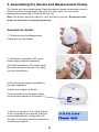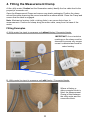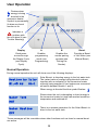
1
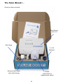
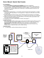
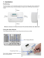
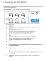
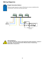
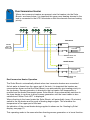
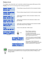
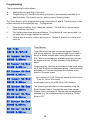
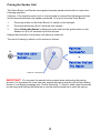
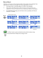
Installation and Operating Instructions Doc No: SM-502 Iss A 01.08.15 Contents Quick Start Guide 5 Installation 6 Connecting the Solar iBoost 7 Assembling the Sender and Measurement Clamp 10 Fitting the Measurement Clamp 11 Testing 12 User Operation 13 Trouble Shooting 18 Further Support 19 Important Notice About Legionella 19 Warranty 19 Technical Specifications Solar iBoost+ Controller: Operating Voltage: 220-240 Vac Control type: 1B Maximum Permissible Loads: 13A Resistive (max 3kW immersion) Rated Impulse Voltage Withstand Insulation Properties 4kV Pollution Degree 2 in accordance with IEC 664 Operating Ambient Temperature Range: 0 to 40°C Approvals: EN 60730-2-7, EN 301 489-3, EN 300 220 Dimensions: 225 x 158 x 92 mm Solar iBoost+ Sender: Battery Type: 2 x AA IEC LR6 1.5V alkaline (supplied) Battery Life Cycle: 1 year (user replaceable) Operating Radio Frequency 868.3 MHz Radio Range Operating Ambient Temperature Range: Approvals: 1 to 30m indoors (dependant on construction and local conditions) -5 to 40°C EN 60950, EN 301 489-3, EN 300 220 Dimensions: 95 x 75 x 35 mm (excluding clamp) 2 Thank you for purchasing a Solar iBoost+. Before use, please read these instructions carefully These instructions provide information on the installation, operation and programming of the unit. Please keep this booklet safe for future reference. The Solar iBoost+ is designed to be used in conjunction with micro-generation systems, e.g. solar PV, where surplus energy generated can be stored within a domestic hot water cylinder in the form of hot water. By monitoring the amount of energy being exported to the National Grid the Solar iBoost+ unit will divert energy into an immersion heater when the energy generated exceeds the amount of energy consumed within the property. Solar iBoost+ controls the energy delivered to the immersion heater in proportion to that exported. Solar iBoost+ Features. Up to two immersion heater connections, when the first immersion heater is satisfied the energy flows automatically to the second immersion heater Manual Boost and programmable Timed Boost (eg. For economy settings) A single, battery powered, wireless sender with measurement clamp Displayed energy saving information Up to 3kW immersion heater capability Solar iBoost+ is pre-programmed for wireless connection to the optional iBoost+ Buddy home energy monitor Checks Before Commencing Installation Please note and ensure the following before commencing any installation... 1. The electrical installation of this device must only be undertaken by a suitably trained and qualified electrician; all local safety standards must be observed. All work must satisfy Building/IEE Wiring regulations in force at the time. 2. Solar iBoost+ is suitable for heating water tanks with up to two immersion heaters rated up to 3kW each which MUST include a working thermostat. 3. There should be NO electronic controls between the Solar iBoost+ and the immersion heater, only direct connections to the immersion and mechanical thermostat are suitable for Solar iBoost+. 4. Where a switch is installed between the Solar iBoost+ and the immersion heater, there should be NO neon lamp on the switch. 3 The Solar iBoost+... Check you have received: Solar iBoost+ main unit Wall fixings 2 × AA Batteries Measurement Clamp Sender (with socket for measurement clamp) (with cable & plug) 4 Solar iBoost+ Quick Start Guide Pre-Installation 1. Read Checks Before Commencing Installation and ensure compliance. 2. Locate a suitably ventilated, flat and vertical surface close to the hot water tank to fix the Solar iBoost+, observing all clearances shown on page 6. Positioning should be convenient for running a cable from a fused spur to the Solar iBoost+ and on to the immersion heater(s). Connection 3. Hard wire the Solar iBoost+ in accordance with the selected wiring diagram on pages 7-9 following IEE Regulations or local regulations. Replace the terminal cover but do not power up. 4. Connect the Measurement Clamp into the Sender and fit the batteries in the Sender. Keep the Sender at 1-2m from the main unit. Do NOT press the button on the Sender. 5. Switch on the power supply to the Solar iBoost+ and a short start up procedure runs until Water Heating Off is displayed. 6. Programme Time and Timed Boosts if desired, see page 15. Locate the Sender 7. At the utility meter (NOT the Generation meter) place the Measurement Clamp over the household main incoming live cable and latch into place. Note that the Clamp must be installed on the utility meter side of any connector (or Henley) blocks. IMPORTANT: the orientation of the clamp must be observed to ensure only excess current is detected and used for water heating. Commissioning 8. To commission, perform the tests shown in section 5. General Scheme Layout Meter Consumer Unit Henley/ Connector Block (if fitted) Utility Fuse Utility Meter Measuring Clamp IMPORTANT ! Ensure the clamp is orientated on the cable correctly as shown on the label. This is critical for correct operation. Sender Unit 5 Consumer Unit 1. Installation Positioning The Solar iBoost+ unit is typically located close to the hot water tank (airing cupboard or similar) and electrically connected between a fused outlet or MCB and the immersion heater. 100mm 100mm 100mm 100mm Minimum clearance is 100mm all around. Do not allow airflow to be obstructed. Fixing the Solar iBoost+ Two hanging brackets and two lower fixing screw points are provided: Rear Hanging Brackets Fixing Screw Points Use screws supplied or suitable screws for the mounting surface. 6 2. Connecting the Solar iBoost+ The Solar iBoost+ installation must be protected against overcurrent by connecting it via a 16A MCB or 13A fused outlet. Remove the terminal cover, terminals are arranged as follows: 220-240V 50Hz Max 3kW SUPPLY L N HTR 1 + _ HTR 2 ! + _ cut-outs for rear cable entry FAN UNIT Terminal Description: SUPPLY L 220-240V Live Input—must be protected by 16A MCB or 13A fused outlet N Neutral Earth (all earth terminals common) HTR 1 Terminals (Connect to Immersion Heater at Top of Tank) + Connect to the Live terminal of the immersion heater, max 13A - Connect to the Neutral terminal of the immersion heater Earth HTR 2 Terminals (Connect to Lower Immersion Heater, if fitted) + Connect to the Live terminal of the immersion heater, max 13A - Connect to the Neutral terminal of the immersion heater Earth Hard wire the Solar iBoost+ in accordance with the selected wiring options on the pages overleaf. Terminals allow the connection of up to 4mm² solid copper conductor or multi-strand cable. Ensure terminals are fully tightened and cable is clamped using the cable clamps provided. Where necessary, invert the plastic cable clamp to provide the correct grip. Replace the terminal cover, do not switch on power at this stage (go to section 3) 7 Wiring Diagrams Single Immersion Heater Where a single immersion heater is fitted (most common installation) the Solar iBoost+ should be connected as shown. SUPPLY L N HTR 1 + HTR 2 _ + _ 220-240V From 16A MCB or 13A fused outlet N L max. 3kW Immersion Heater and Thermostat All installations Test that the thermal cut-out in the immersion heater functions, replace if necessary. Do not install the Solar iBoost+ where a functioning thermostat is not present. 8 Dual Immersion Heater Where two immersion heaters are present, wire the heaters into the Solar iBoost+ as shown below. It is important the upper most heating element in the tank is connected to the HTR1 terminals so that this element receives heating priority. SUPPLY L N HTR 1 + _ HTR 2 + _ TOP Heater 220-240V From 16A MCB or 13A fused outlet N L max. 3kW Immersion Heater and Thermostat LOWER Heater N L max. 3kW Immersion Heater and Thermostat Dual Immersion Heater Operation The Solar iBoost+ automatically detects when two immersion heaters are connected. As hot water is drawn from the upper part of the tank, it is important the heaters are connected as shown so that the Solar iBoost+ can automatically give heating priority to the top heater. Excess generation is diverted to the top heater until temperature is reached and the heater thermostat opens. Solar iBoost+ then automatically switches to the lower heater to continue to divert excess generation until the lower heater is also satisfied and ‘Water Tank HOT’ is displayed. When diverting to the lower heater the Solar iBoost+ will periodically (every 15 minutes) switch to the top heater and the cycle of heating begins again. This maintains the temperature in the upper part of the tank. An indication of the current heater being supplied is shown on the ‘Heating by Solar’ display, see page 13. This operating mode is the same whether diverting excess generation or in boost function. 9 3. Assembling the Sender and Measurement Clamp The Sender unit has a Measurement Clamp that detects export current when correctly fitted on the live incoming supply cable from the utility meter. The unit sends measurements wirelessly to the Solar iBoost+ unit. Note: The Sender and Solar iBoost+ units are factory paired. Do not press the button on the sender or pairing may be lost. Assemble the Sender 1. Fit the plug from the Measurement Clamp wire into the Sender. 2. Fit batteries (included) or DC mains power supply (supplied separately). When fitting batteries or DC power supply the sender should be at least 1-2m away from the Solar iBoost+ A DC mains power supply is available to purchase separately. Contact your supplier for details. Fit the connector from the power supply into the socket marked on the sender. 3. Switch on the power to the Solar iBoost+. A set up procedure runs and the 2 devices connect automatically, usually within 30 seconds. If necessary follow the instructions for pairing on page 16. 10 Initialising Please Wait 4. Fitting the Measurement Clamp At the utility meter (Caution! not the Generation meter) identify the live cable feed to the property’s consumer unit. Open the Measurement Clamp and remove any plastic packaging. Position the clamp around the cable observing the correct orientation as shown below. Close the Clamp and ensure that the latch is engaged. Note: Mechanical meters (with rotating disks) can cause distortions to measurements. Position the clamp along the meter cable, away from the base of the meter. Fitting Examples A. Utility meter live input to consumer unit without Henley /Connector blocks. IMPORTANT: the orientation markings on the clamp must be observed to ensure only excess current is detected and used for water heating. B. Utility meter live input to consumer unit with Henley / Connector blocks. Where a Henley or other connector block is fitted, the Measurement Clamp is fitted between the utility meter and the connection block. 11 5. Test the System These tests are designed to verify that only excess generation is used by the Solar iBoost+. Installers must check that increased energy consumption in the home results in less energy being supplied into the immersion heater. This is indicated in the ‘Heating by Solar’ display. The availability of high energy appliances (e.g. kettle, electric showers etc.) are useful during these tests. Before testing, if “Tank Hot” displays, run off some hot water. Perform tests 1, 2 and 4. When there is no PV generation, perform tests 3 and 4 . Test 1 When sufficient excess generation is available and “Heating by Solar” is displayed, check that the Solar iBoost+ stops diverting energy when the PV system is off. Shutdown the PV array and the display changes to “Water Heating OFF.” Reinstate the PV array. Test 2 When the PV generation is above 100W, check that switching off appliances in the home results in greater energy diversion by the Solar iBoost+ unit. Shut down all the MCB’s / Fuses except for the PV and immersion. Check the level of PV generation on the inverter. The “Heating by Solar” level should be approximately 100W less than generation. Reinstate MCB’s / Fuses. NB. If no reading is possible from the inverter a reduction in “Heating by Solar” value or “Water Heating OFF” should be seen after the MCB’s / Fuses have been reinstated, switch on a high energy appliance if necessary. Test 3 At times when no PV generation is available (e.g. commissioning after dark) test the installation by simulating export energy, achieved by reversing the orientation of the Measurement Clamp. Shut down the PV array Reverse the orientation of the measurement clamp (consumption in the home is then measured as export energy) Switch on a kettle or high energy device Whilst the kettle is on “Heating by Solar” is displayed and Solar iBoost+ function is proved. IMPORTANT! Return the clamp to its correct operating position and reinstate the PV array. Test 4 Test the boost function is operational. Press the Boost button 2 times, “Manual Boost ON” displays Check that water is heating Scroll the Boost button until it reads “Manual Boost OFF” 12 User Operation Flashes when energy is being diverted to the immersion heater. Symbol is permanently lit when any boost function is on Indicates a problem with the unit when lit (see Trouble Shooting) ! Display A B Boost Each press moves through the Display Cycle (see Display Cycle) Enables programming mode (see Programming) Enables the sender pairing process (see Pairing the Sender) Provides a Boost of Hot Water (see Manual Boost) Normal Operation During normal operation the unit will show one of the following displays: Heating by Solar 01.45 kW Htr1 Solar iBoost+ is diverting energy to the hot water tank. The instant value of energy being diverted is shown together with an indication of the immersion heater currently being supplied (if two heaters are connected will switch between Heater 1 and 2). When energy is diverted the blue symbol flashes: Water Tank HOT Water Heating Shown when the unit is attempting to divert energy to the immersion heater but tank has reached maximum temperature and switched off. There is no excess generation for the Solar iBoost+ to divert to the hot water tank. OFF These messages will be overridden when other functions such as timed or manual boost are active. 13 Display Cycle The display cycle allows the user to view the recorded energy saving. Each press of the Display button will move through the following sequence : Present days energy diverted into the immersion heater Saved Today 03.66 kWh Saved Yesterday Previous days energy diverted into the immersion heater 10.56 kWh Saved Last 7 days 03.66 kWh Saved Last 28 days 65.53 kWh Saved Amount Total energy diverted into the immersion heater in the past 7 days Total energy diverted into the immersion heater in the past 28 days Total value of energy diverted into the immersion heater since Solar iBoost+ was installed 390.20 kWh Current time and date in 24hr format Time 10:15 01/07/15 In Winter Boost Toggle Press A Boost Season selection. A Press Hot water boosts can be programmed for different seasons (see programming section). Final press In Summer Boost Toggle Press A Timed Boosts Off The boost season can be changed here by pressing the A button when required. Each press of the A button will change the setting between Summer, Winter and Boost OFF selections. Toggle Press A Switching the timed programme function between Winter/Summer/OFF can be activated remotely within the home using the optional iBoost+ Buddy home energy monitor. 14 Programming The programming function allows: Setting the time and date of the clock Programming of Timed Boosts when grid power is automatically switched on to heat the water. This feature can be used in place of existing timers. The Solar iBoost+ unit is programmed using push buttons A and B. The first press of any button switches on the backlight only. To programme: 1. Press and hold button A for 3 seconds, release. The first item in the sequence below is shown (set time). 2. The first digit becomes active and flashes. Press button B, each press adds 1 to the value until the digit required is reached. 3. Press button A once to confirm and move on. Repeat 2, press A to confirm and move on. Set Time Timed Boosts 10:15 01/07/15 Timed Boost periods can be entered against Summer and Winter seasons. This enables longer boost times to be set in Winter periods when solar generation maybe less. Two boost periods are available each day and can be programmed on a 5 day weekday/2 day weekend basis. B1 Summer Wk/Day 00:00 0.00hrs B2 Summer Wk/Day 00:00 0.00hrs B3 Summer Wk/End 00:00 0.00hrs B4 Summer Wk/End 00:00 0.00hrs B5 Winter Wk/Day 00:00 0.00hrs B6 Winter Wk/Day 00:00 0.00hrs Programme the start time and duration of the boost using the A and B buttons as described above. Start times are selectable in 15 minute steps and the duration of the boost in 30 minute steps. e.g. a setting of 07:00 1.5hrs will switch on the boost at 7 am for 1 hour 30 minutes. An unused boost is left at 00:00 for 0:00 duration. The operating boost season is set manually using the Boost Season feature found at the end of the normal Display Cycle, see page 14. Boosts may be temporarily disabled (e.g. for holiday periods) by selecting ‘Timed Boosts OFF’. B7 Winter Wk/End 00:00 0.00hrs B8 Winter Wk/End 00:00 0.00hrs 15 Pairing the Sender Unit The Solar iBoost+ and Sender are supplied uniquely paired and should not require the following operation. However, if the signal becomes lost or a new pairing is required the following procedure should be performed with the sender positioned 1m or more from the Solar iBoost+. 1. Press any button on the Solar iBoost+ to switch on the backlight. 2. Press and hold button B for 5 seconds then release. 3. When Pairing with Sender is displayed, press and hold the green button on the Sender for up to 10 seconds to pair the devices. Repeat the procedure if necessary until pairing is achieved. The result of pairing is shown on the screen as follows: Pairing B Successful Pairing with or Sender... Pairing failed Try Again Press for 10 seconds IMPORTANT! Do not press the sender button except when performing the pairing process. If it is pressed for more than one second the pairing may be lost and the display shows a ‘Lost Signal’ message (see Trouble Shooting). To correct, either reset the sender by removing and refitting the batteries or use the above procedure to reset the pairing. 16 Manual Boost Switches on full power to the immersion heater for the period of time selected. Note that electricity is drawn from the grid if the excess generation is too low. 1. Press any button on the Solar iBoost+ to switch on the backlight. 2. Each press of the Boost button adds 15 minutes to the boost time up to maximum of 2 hours. The amount of time remaining is shown on the display. 3. To cancel the boost simply press the Boost button repeatedly until ‘Manual Boost OFF’ is shown. First Boost button press Boost Manual Boost ON Manual Boost ON Manual Boost ON for 15 mins for 30 mins for 45 mins Manual Boost ON Manual Boost ON Manual Boost ON for 60 mins for 75 mins for 90 mins Manual Boost ON Manual Boost ON Manual Boost for 105 mins for 120 mins OFF Final press The Boost function can be activated remotely within the home using the optional iBoost+ Buddy home energy monitor. 17 Troubleshooting - Warnings and Messages The Solar iBoost+ internal diagnostics notify if any fault arises in the system. When a fault is detected the red warning triangle on the front of the unit is illuminated. A message on the display details the specific fault: Sender Battery LOW Lost Signal to Sender Unit Cooling... Check vents Maximum Power Exceeded Htr 1 ! Batteries are low in the sender unit – replace batteries at earliest opportunity. Do not use rechargeable batteries. The unit is no longer receiving messages from the sender unit. Possible causes: 1. Batteries may be exhausted. 2. Solar iBoost+ is positioned too far or near to the sender. 3. Sender unit pairing button may have been pressed inadvertently outside of the pairing process (see Pairing the Sender). The Solar iBoost+ unit is over its working temperature check that the unit is clear of obstructions and that there is adequate airflow to the unit. The unit will automatically recover when the internal temperature has reduced to within the normal operating range. The Solar iBoost+ will check for overload during initialisation and during normal operation. If overload of either heating circuit is detected the output will be disabled. Check the load of the immersion heater and supply voltage are within specification. This warning can be reset by power cycling the Solar iBoost+ unit. Shutting Down Solar iBoost+ can be left to operate year round. Should you wish to power it down (e.g. during holidays) the following options are possible: Switch off at the fused spur - No solar energy will be captured by the Solar iBoost and timed settings will not operate. Temporarily remove the batteries from the sender - No solar energy will be captured but timed settings will continue to operate. Select OFF in Winter/Summer/OFF timed settings. Solar energy will be captured but timed settings will not operate. Accumulated savings and programmed times are retained in memory. 18 Further Support To find out more about how Solar iBoost+ works visit www.solariboost.co.uk Consult your qualified installer / electrician for any user queries. Technical support for qualified installers and electricians +44 (0) 1536 447866 Important Information about Legionella Legionella bacteria are common and can be found naturally in environmental water sources such as rivers, lakes and reservoirs, usually in low numbers. As legionella bacteria are commonly encountered they may eventually colonise manufactured water systems and if conditions are favourable the number of bacteria may grow. Contamination risks are however low due to the low availability of nutrients and the regular chlorination of the water supply. As with any hot water storage system it is important to avoid water stagnation and ensure the water is regularly heated to a minimum temperature of 55-60°C to reduce potential risks. It is therefore recommended that the hot water tank be heated to 55-60°C at least once per week either using Boost facility or through other heating controls. Limited Warranty The SIB Energy Company Limited Warranty provides free replacement cover for all defects in parts and workmanship for 24 months from the date of purchase. SIB Energy Ltd obligation in this respect is limited to replacing parts which have been promptly reported to the seller and are in the seller’s opinion defective and are so found by SIB Energy Ltd upon inspection. A valid proof of purchase is required if making a warranty claim. Defective parts must be returned by prepaid post and accompanied by a Returns Authorisation available in advance from Marlec Engineering Company Limited, Rutland House, Trevithick Road, Corby, Northamptonshire, NN17 5XY, England, or to an authorised agent. This Warranty is void in the event of improper installation, unauthorised service, use of unauthorised components, owner neglect, misuse or natural disasters including lightning strike. This warranty does not extend to ancillary equipment not supplied by the manufacturer. No responsibility is assumed for incidental damage. No responsibility is assumed for consequential damage. Disclaimer SIB Energy Limited has a policy of continuous improvement in product quality and design. The company, therefore reserves the right to change the specification of its models at any time. All items in this guide are for illustration purposes only and may not apply to your particular situation. Disposal of Old Electrical Appliances For electrical products sold within the European Community. At the end of this products useful life, it should not be disposed of with household waste. Please recycle where facilities exist. Check with your local authority or retailer for recycling advice in your local area. SIB Energy Limited ⁞ Peterborough 19 ⁞ PE3 6SR Maximise the Benefit of Your New Solar iBoost+ We want you to get the most from owning Solar iBoost+ so here’s a few tips to help capture and save more energy using your Solar iBoost+. Reduce or Delay the “ON” Periods of your Current Water Heater Change your heater settings to later in the day, after sundown if possible, as this allows the Solar iBoost+ to preheat water in the tank using the excess PV energy. Normal water heating will topup to the thermostatically set temperature of your tank so you have plenty of hot water available but your usual fuel usage and costs will be reduced. Adjust any morning settings according to your household need but mindful that greater benefits are achieved if there is excess PV available and the tank is not already hot at the start of the day. Consider which Immersion Heater to Connect to Single Immersion Systems are normally installed at the top of the tank and additional benefit is gained by installing a longer immersion or a de-stratification pump to circulate the hot water throughout the tank. Dual Immersion Systems – we recommended connecting the top immersion heater to HTR1 and the bottom to HTR2, enabling the whole tank to benefit from the cascading PV energy feature. When the top immersion heater is satisfied the energy diverts to the bottom immersion heater automatically. The system regularly checks that top immersion heater remains fully satisfied. Vary your Heating Times by Season In Summer months the Solar iBoost+ alone may provide a plentiful supply of hot water and other water heating systems can be temporarily switched off. When required the built-in Boost feature can be used for short top-ups from the grid. This is activated on the Solar iBoost+ or remotely using the iBoost+ Buddy if installed. Using the Winter / Summer / Off timed programming feature you can set and store 2 timed periods of grid power operation on a 5 day/2 day basis for Winter and Summer. Simply swap between the stored settings at the press of a button on the Solar iBoost+ or remotely on iBoost+ Buddy if installed. This timer can, in most circumstances, replace existing economy tariff timers on electrical water heating systems. OFF can be simply selected during holiday periods. Ensure Your Water Tank is Well Insulated Enjoy the free warm water for longer. Water consumed in the morning will allow a new day’s “Heating By Solar” to begin again, maximising your PV system with your Solar iBoost+. Minimise the Base Levels of Energy Consumption in your Property Reducing your home’s energy consumption will maximise the excess power available for Solar iBoost+ to divert. For example instead of using standby why not power down appliances when not in use? Add an iBoost+ Buddy It’s the ideal energy monitor and remote control accessory for Solar iBoost+ . Find out if you are generating spare free PV energy to optimise your self consumption once your water tank is hot. Its intuitive traffic light system with easy to read display keeps you informed of your available generation. Installation is simple as it pairs to your Solar iBoost+ with a press of a button. Visit www.solariboost.co.uk for more information. 20