1
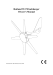
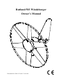
Rutland 503 Windcharger
Owner’s Manual
Document No. SM-115 Issue C 16.06.04
Rutland 503 Windcharger
Owner’s manual
Contents
Page
INTRODUCTION................................................................................ 2
CHECK YOU HAVE RECEIVED....................................................... 4
WHAT YOU WILL NEED.................................................................. 4
SITING THE WINDCHARGER.......................................................... 5
General Considerations........................................... 5
On Board Systems.................................................. 6
Land based Systems................................................ 7
ASSEMBLY & INSTALLATION........................................................ 8
Tail Assembly......................................................... 8
Tower Preparation………….................................. 8
BATTERIES........................................................................................
9
CABLE SPECIFICATION................................................................... 9
ELECTRICAL CONNECTION & FITTING TO THE TOWER......... 10
FINAL MECHANICAL CHECK…………………………………… 10
ASSEMBLY OF IN-LINE FUSE HOLDER………………………..
11
BASIC WIRING DIAGRAMS............................................................ 12
UP AND RUNNING...........................................................................
13
SPECIFICATION AND PERFORMANCE......................................... 13
INSPECTION AND MAINTENANCE............................................... 14
TROUBLESHOOTING....................................................................... 15
Document SM115 Issue C 16.06.04
1
Marlec Engineering Co Ltd
Rutland 503 Windcharger
Owner’s manual
INTRODUCTION
This manual contains important information concerning your Rutland 503
Windcharger and its installation and operation.
It is strongly recommended that you read this manual and familiarise yourself
with its contents before installing and operating the Windcharger system.
The Rutland 503 Windcharger is designed to provide a direct current (DC)
power supply via a battery bank for 12V equipment, lighting, etc. It is intended
for use on small to medium size sailing vessels and can be used for temporary
installation on caravans and motorhomes. It is robustly constructed and designed
to give many years of trouble free service with the minimum of maintenance.
Please take notice of our General Guidelines & Warnings, and Inspection and
Maintenance sections.
GENERAL GUIDELINES &WARNINGS!
• Mounting pole outside diameter MUST NOT exceed 38.1mm for at least the
top 0.5m. Larger section poles must not be used as this will reduce the tower
to blade clearance. In high wind conditions this could cause damage to the
windcharger by allowing the blade to come into contact with the mounting
pole. A broken blade or rim will cause turbine imbalance with consequent
damage.
• When turning, the Windcharger is capable of generating voltages in excess of
the nominal voltage. The turbine must never be allowed to rotate unless it is
electrically connected to a regulator or batteries. Avoid applying a short
circuit to the Windcharger particularly in high winds. If a short circuit is
necessary first slow the turbine as described below. Caution must be
exercised at all times to avoid electric shock.
• Stopping the turbine – this may be necessary to undertake battery
maintenance. If possible stopping the turbine should be done in low
windspeed conditions. The turbine can be slowed by rotating or orienting the
tail fin upwind, this will slow the turbine sufficiently for it to be safely secured
to the pole with rope. Avoid leaving the turbine tied up for any period of time,
we recommend that the turbine either be covered to give protection from the
weather or removed and stored in a dry location
• No attempt to repair the system should be made until the wind generator is
restrained from turning.
Document SM115 Issue C 16.06.04
2
Marlec Engineering Co Ltd
Rutland 503 Windcharger
Owner’s manual
• The Windcharger is fitted with ceramic magnets which can be damaged by
heavy handling. The main generator assembly should be treated with care
during transit and assembly.
• It is essential to observe the correct polarity when connecting the
Windcharger and all other components into an electrical circuit. Reverse
connection will damage the Windcharger and incorrect installation will
invalidate the warranty.
• The fuse supplied must be fitted to protect the system unless used in
conjunction with a controller that is already fitted with a charge fuse.
• High winds - the Rutland 503 Windcharger is suitable for sailing boats and
some land based applications. When storm winds are forecast the turbine can
be restrained to minimise wear and tear particularly when installed on high
windspeed site land based applications where Furlmatic model windchargers
are normally recommended. Note that where the manufacturer recommends a
furling type windcharger should have been used the warranty is invalidated in
cases of storm damage.
• If in doubt, refer to your dealer, a competent electrical engineer or the
manufacturer.
Document SM115 Issue C 16.06.04
3
Marlec Engineering Co Ltd
Rutland 503 Windcharger
Owner’s manual
CHECK YOU HAVE RECEIVED
•
•
•
•
•
•
•
1 x main generator assembly
1 x Tail Fin
2 x M8 x 16 Button Cap Screws & Shakeproof Washers
2 x M6 x 12 Hex Head Screws, spring washers & plain washers
1 x fuse and fuse holder. Fuse Rating 7.5A.
1 x 2-way terminal block
1 x 5mm Allen Key
In the event of loss or damage, consult your dealer or the manufacturer.
WHAT YOU WILL NEED
Tools
• Suitable wire stripper
• Small terminal screwdriver
• 10mm Spanner or Socket
Other Items You Will Need
•
•
•
•
•
Mounting pole
Cable
Batteries
Battery terminals
Connector blocks (as determined by your total system)
Other Items You May Have Selected
• HRS503 Regulator or HRDX Charge Controller
• Cable
• Rutland 503 Marine Mounting Kit (Part No: CA-12/01)
• Rutland 503 Land Tower & Rigging Kit (Portable) (Part Nos: CA12/12 & CA-12/13)
• Short section of stainless steel tube to adapt to your own mounting design.
• Voltmeter & Ammeter
Document SM115 Issue C 16.06.04
4
Marlec Engineering Co Ltd
Rutland 503 Windcharger
Owner’s manual
SITING THE WINDCHARGER
General Considerations
The location and height of the mounting pole or tower for your wind turbine will
be the major factor in the overall performance of your system.
The smooth flow of wind over land and water is often interrupted by a multitude
of obstructions causing wind sheer and turbulence.
Wind sheer describes the interference between the fast moving upper air and
the slow moving air close to the ground and the resulting decrease in average
wind speed as one gets closer to the ground.
Turbulence is caused by the wind passing over obstructions such as moored
boats, trees and buildings. Both wind sheer and turbulence diminish with height
and can be overcome simply by putting the turbine sufficiently high above them.
It is therefore essential that the wind generator should be located in an area as
free as possible from disturbed wind flow. Bear in mind that downwind
obstructions can be as detrimental to performance as upwind obstructions
(Fig.1).
AREA OF TURBULENCE
Fig.1
WIND DIRECTION
2H
H
2H
Document SM115 Issue C 16.06.04
20H
5
Marlec Engineering Co Ltd
Rutland 503 Windcharger
Owner’s manual
On Board Systems
Fig.2
The wind generator should be mounted in a
safe position, a minimum of 2 metres (6.5
feet) above the deck and away from other
obstacles which could interfere with the
blades or tail assembly (Fig. 2).
Fig.3
The Rutland 503 Mounting Kit (Part No:
CA-12/01) is available for deck mounting or
short sections of stainless steel tube of
500mm & 1m pre-drilled are available to
adapt to your own fabrication.
The Rutland 503 is designed to fit inside an
aluminium or stainless steel tube with an
internal diameter of 31.7mm (11/4”). The
external diameter must not exceed 38.1mm
(1½”), see Warnings! Suitable tube: 11/2“ 10
SWG aluminium or Stainless Steel
35mmx1.5mm.
Fig.4
We suggest the following mountings
according to preference and site conditions:
• Pushpit (Fig.3)
A suitable pole mounted to the deck with
deck plates and rigid guys is the most
popular
method
of
mounting
the
Windcharger on yachts, e.g. Rutland 503
Mounting Kit.
Fig.5
• Mizzen (Fig.4)
Mizzen mounting is suitable on larger
yachts, taking advantage of greater wind
flow the higher the wind turbine is mounted.
• River Boats (Fig.5)
A pivot pole is ideal for river boats as the
Windcharger can easily be raised and
lowered.
Document SM115 Issue C 16.06.04
6
Marlec Engineering Co Ltd
Rutland 503 Windcharger
Owner’s manual
Fig.6
Land Based Systems
The Rutland 503 is designed to fit inside an
aluminium or stainless steel tube with an
internal diameter of 31.7mm (11/4”). Max
external diameter 38.1mm (1½”).
A suitable mounting pole can be erected
using a 6.5 metre (21 feet) length of 50mm
(2”) galvanised water pipe adapted down to
31.7mm for a minimum length of 500mm at
the top section.. The tube must be supported
by a minimum of two sets of three guy lines.
Centre pivoted pole
Fig.7
Base pivoted with gin pole
The attachment points for the guy lines to the
tower should be securely fixed to the tower.
• The guy wires should be a minimum of
3mm in diameter.
• The shackles should be a minimum of
5mm in diameter.
• Rigging screws should be a minimum of
5mm in diameter.
• All items should be galvanised or stainless
steel for protection against corrosion.
• Where guy lines are looped, the loop must
incorporate a thimble and be fitted with a
minimum of three rope grips.
• All ground fixings must be made suitable
according to the terrain.
We suggest pivot type towers as these allow
for easier installation and lowering for access
to the wind generator. Two forms of pivot
tower are suggested in Figs 6 & 7.
A portable Land Tower and Rigging Kit is
available from Marlec.
Part Nos: CA-12/12 & CA-12/13
Document SM115 Issue C 16.06.04
7
Marlec Engineering Co Ltd
Rutland 503 Windcharger
Owner’s manual
Fig.8
ASSEMBLY AND INSTALLATION OF
THE WINDCHARGER
Tail Assembly (Fig.8)
1. Place the generator assembly on a flat soft
surface, Nose Cone down.
2. Fit the tail into position on the protruding
portion of casting and against the Nacelle,
ensuring the holes in the casting align with
the corresponding holes in the tail fin.
3. Secure the Tail fin in position with the 2
M6 screws and washers, ensuring the plain
washers are against the tail fin.
4. Check tightness of all screws. (Do not
over-tighten).
Tower Preparation (Fig.9)
Having selected a suitable pole from the
guidelines on pages 6 and 7:
Fig.9
1. The post adapter fitted to the 503 is
designed to fit inside a standard 31.7mm
internal diameter tube. Max external
diameter 38.1mm (1½”).
40mm
2. Mark and centre-punch two positions
diametrically opposite, at 90° to the pipe
seam if necessary, 40mm from top of the
tube.
3. Drill two holes 8.5mm in diameter on
centre-punch positions.
Note: When using the Rutland 503 Mounting
Kits, items 2 and 3 can be ignored, as these
are pre-drilled.
Document SM115 Issue C 16.06.04
8
Marlec Engineering Co Ltd
Rutland 503 Windcharger
Owner’s manual
BATTERIES
Fig.10
Leisure/Deep Cycle batteries are specifically
designed for good performance in terms of
charge/discharge cycles. Batteries are the
most important part of your battery charging
system and should be sized according to your
load requirements and provide at least 3 days
reserve capacity. This will reduce cycling,
prolong the life of the battery and ensure
system reliability during periods of low
wind.
Total = 12v
120Ah
1440Wh
12v
60Ah
12v
60Ah
In parallel to increase
amp hours (Fig.10).
Permanent connections should always be
made to the battery terminals. Never use
crocodile clips or similar devices. Battery
terminals should be well greased with
petroleum jelly or similar.
Fig.11
We strongly recommend that one of the
charge regulators available from Marlec is
fitted to prevent batteries becoming
overcharged in strong winds and is essential
with gel and sealed batteries.
Total = 24v
60Ah
1440Wh
12v
60Ah
12v
60Ah
Batteries may be linked as shown in the
Figures 10 and 11. It is essential to observe
polarity as follows:
Red is + Positive
Black is - Negative
In series to increase voltage
(Fig 11).
CABLE SPECIFICATION
Cable
Run (m)
0-20
21-30
31-45
46-80
Cable Size
(mm²) SWG AWG
2.5
4
6
10
15
13
11
9
13
11
9
7
The cable used for connection of the
Windcharger to the batteries should be in
accordance with table 1. The use of a smaller
cable than recommended will reduce the
performance of the charging system.
Cable and connectors are available from your
dealer or the manufacturer.
Table.1
Document SM115 Issue C 16.06.04
9
Marlec Engineering Co Ltd
Rutland 503 Windcharger
Owner’s manual
ELECTRICAL CONNECTION & FITTING TO THE TOWER
1. Run the cable selected down the inside of the pole.
2. Select one of the 2 basic wiring systems on page 12 and follow the manual
provided with the regulator or controller. Fit the fuse according to the
instructions “Assembly of the In-Line Fuse Holder.” It is essential that a
charge fuse is fitted but note that some Marlec Controllers incorporate one
negating the need for a separate fuse.
3. Connect the wind generator flying leads to the cable protruding from the tower
using the connector block supplied, taking care to observe polarity. Connect
the windcharger + to the cable + and windcharger – to cable –
Red is + Positive
Black is - Negative
4. Wrap the connection with insulation tape to secure/protect from environment.
Alternatively join the cables using a latching-type plug and socket.
5. Locate the wind generator into the tower whilst gently easing the cable from
the tower base to ensure the cable is not trapped. Secure the wind generator
to the tower using the buttoncap screws and shakeproof washers provided,
tighten using the 5mm Allen key provided.
FINAL MECHANICAL CHECK
1. Check the tightness of tail fixing screws and generator mounting screws.
2. Check free rotation of the hub and yaw axis.
Document SM115 Issue C 16.06.04
10
Marlec Engineering Co Ltd
Rutland 503 Windcharger
Owner’s manual
ASSEMBLY OF THE IN-LINE FUSE
HOLDER
Note: It is not necessary to fit the in-line
fuse holder if a HRDX controller is to be
used.
2
3
Select a suitable position to mount the in-line
fuse, this should be in the positive lead
between the regulator and the battery.
3
Each Pack consists of: Item 1 & 2
Item 3
Item 4
Item 5
5
4
One Plastic Holder.
Two Electrical Connections.
One Spring.
One Fuse.
1
1. Insert the positive wire from the battery
and regulator into each half of the plastic
holder (1 & 2)[See fig.12].
2. Place the spring over the cable inside the
longer (1) of the two plastic holders [See
fig.12].
3. Bare a small amount of wire from the
ends of the cable, twist the copper wire
crimp and solder the electrical connections
(3) onto the ends.
4. Insert the fuse and twist the two halves of
the holder together to complete the electrical
circuit [See fig.13].
Fig. 12
Fig. 13
Note: When fully assembled please
ensure the electrical connections make
direct contact with the fuse.
Document SM115 Issue C 16.06.04
11
Marlec Engineering Co Ltd
Rutland 503 Windcharger
Owner’s manual
Rutland 503 with HRS503 Regulator
HRS503
Regulator
12V
Rutland 503
Red
Brown
Black
Black
Red
Charge Fuse
Battery 12V
Rutland 503 with HRDX Controller
HRDX
Controller 12V
Rutland 503
Solar Panel.
Maximum
100Watts
Red
Black
Black
Red
Black
Red
Battery 12V
Battery 12V
Document SM115 Issue C 16.06.04
12
Marlec Engineering Co Ltd
Rutland 503 Windcharger
Owner’s manual
UP AND RUNNING
• Before raising and securing the wind generator, check that:
1. All final mechanical checks have been made.
2. The cable is not trapped.
3. All electrical connections are secure and safe.
• The wind generator can now be raised into position.
Take care to avoid all moving parts when raising and lowering the wind
generator.
• When raised, secure the structure firmly in an upright position. The
performance of your Windcharger can be impaired if the pole is not vertical.
SPECIFICATION AND PERFORMANCE
The curve shown below is for ideal, non-turbulent wind conditions; this may not be achieved in some
installations.
Charge into 12v battery (Amperes)
6.0
WINDSPEED CONVERSION
5.0
WINDSPEED
MPH
= KnotsCONVERSION
x 1.15
MPH = Knots x 1.15
M/S
= Knots x 0.515
4.0
M/S = Knots x 0.515
3.0
2.0
1.0
0.0
0
5
10
15
20
25
30
35
Windspeed (Knots)
Document SM115 Issue C 16.06.04
13
Marlec Engineering Co Ltd
40
Rutland 503 Windcharger
Owner’s manual
INSPECTION AND MAINTENANCE
The Rutland 503 requires no scheduled maintenance but an annual inspection
should be carried out to monitor the general condition of the system to ensure
the electrical and mechanical integrity and safety of the system.
WARNING! Before inspection, the turbine should either be lowered to the
ground or tied to prevent the generator from turning. To stop the generator from
turning proceed as follows:
1) Turn the wind generator out of the wind (180°) using the tail. A hole is
provided in the tail fin to assist in this. The generator will eventually slow
down.
2) Tie a blade to the mounting pole to prevent it from rotating.
• Whilst the generator is stationary, the following routine checks should be
performed:
1) Check all nuts, bolts and screws for tightness.
2) Check the yaw axis for free rotation.
3) Check tower assembly for condition.
4) Check the tension of the guy wires if applicable. The tension of guy wires
should be checked frequently during the first year.
5) The unit can be wiped with a mild detergent and rinsed with water to remove
dirt and debris.
Note: The Windcharger is designed for continuous running to achieve maximum
resistance to water ingress, should the unit be restrained for any extended
period it is recommended that it be covered.
Document SM115 Issue C 16.06.04
14
Marlec Engineering Co Ltd
Rutland 503 Windcharger
Owner’s manual
TROUBLESHOOTING
In the unlikely event that your Rutland 503 should develop a defect, the turbine
should first be tied to prevent the blades from turning to perform the static tests
below. (Follow the procedure described in the Inspection and Maintenance
section) It will be necessary to let it run for the tests to check for power
production.
1. Read the Electrical Connection and Up and Running sections and be
satisfied that your system complies.
2. Is there sufficient wind? The Rutland 503 needs 5 knots wind speed to start
charging. The wind speed across the turbine blades may be greatly reduced in
a marina or built-up area compared with the reading on a masthead
anemometer or weather reports.
3. Static Tests:
• Is the battery in good condition? Check the voltage and electrolyte level of
each battery.
• Check electrical continuity throughout the system, especially corrosion and
poor connections in cable joins and connector blocks.
4. Running Tests:
• Check for power output from the windcharger, following this procedure:
A. Set a digital multimeter to DC Amps, scale of up to 5A or less if possible.
Connect the meter positive (+) probe to the wind gen output positive cable
and the meter negative (-) to the regulator input positive. Provided there is
sufficient wind there should be a current reading. This establishes that power
is being delivered.
B. Using the same multimeter setting as above measure between the “regulator
to battery” + and the battery +. Provided there is sufficient wind there should
be a current reading. This establishes if power is passing through the
regulator.
C. If both above are unsuccessful set the multimeter to DC Volts. Disconnect
the wind generator from the regulator and connect the meter + to the wind
gen + and the meter – to the wind gen -. Provided there is sufficient wind
there should be a variable voltage reading according to the speed of the wind
seen at the wind turbine. This will establish if the wind generator is able to
deliver power or not.
D. If tests A and C are successful but test B fails to produce results connect the
wind gen directly to the battery. Set the digital multimeter to DC Amps and
measure power between the wind gen + and the battery +. If a reading is
measured, providing there is sufficient wind, then the regulator is faulty.
Document SM115 Issue C 16.06.04
15
Marlec Engineering Co Ltd
Rutland 503 Windcharger
Owner’s manual
E. If the wind turbine fails to deliver any current or open circuit V reading
undertake the further tests below.
5. Mechanical inspection. It may be necessary to remove the windcharger from
its pole for the following tests.
• Check the brushes and slipring for wear or damage. To inspect the
brushes, remove the tail fin and the plastic nacelle. The brushes can be
inspected by removing the caps from the brush holders & withdrawing the
brushes. Heavy deposits on the slipring and reduced power indicate a possible
reverse connection to the battery.
• Check hub for free rotation with generator disconnected from battery.
If the hub does not rotate freely, check for a possible short circuit in the
wiring.
If no wiring fault is found refer to your dealer or manufacturer.
If the above checks have identified a need for spare parts or failed to identify
the problem you should contact Marlec who can advise you of your nearest
distributor in their world wide network. In the first instance we recommend that
you contact the company from whom the product was originally purchased.
If in doubt, refer to your dealer or manufacturer.
Document SM115 Issue C 16.06.04
16
Marlec Engineering Co Ltd
Rutland 503 Windcharger
Owner’s manual
For your future reference we recommend you note the following:
Serial Number:
Date of Purchase:
Date of Installation:
Type of Regulator:
Document SM115 Issue C 16.06.04
17
Marlec Engineering Co Ltd
LI M I T E D W A R R A N T Y
The Marlec Engineering Company Limited Warranty provides free replacement cover
for all defects in parts and workmanship for 12 months from the date of purchase.
Marlec's obligation in this respect is limited to replacing parts which have been
promptly reported to the seller and are in the seller’s opinion defective and are so found
by Marlec upon inspection. A valid proof of purchase will be required if making a
warranty claim.
Defective parts must be returned by prepaid post to the manufacturer Marlec
Engineering Company Limited, Rutland House, Trevithick Road, Corby,
Northamptonshire, NN17 5XY, England, or to an authorised Marlec agent.
This Warranty is void in the event of improper installation, owner neglect, misuse,
damage caused by flying debris or natural disasters including lightning and hurricane
force winds. This warranty does not extend to support posts, inverters, batteries or
ancillary equipment not supplied by the manufacturer.
No responsibility is assumed for incidental damage. No responsibility is assumed for
consequential damage. No responsibility is assumed for damage caused by the use of
any unauthorised components.
No responsibility is assumed for use of a non "furling" versions of the Rutland
Windcharger where Marlec or one of its authorised agents finds that a generator
incorporating a furling device should have been used.
Manufactured in the UK by
Marlec Engineering Co Ltd
Rutland House,
Trevithick Rd,
Corby, Northants,
NN17 5XY UK
Tel: +44 (0)1536 201588 Fax: +44 (0)1536 400211
Email: [email protected]
www.marlec.co.uk