1
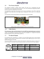
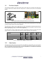
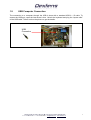
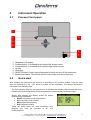
Ozone Process Gas
Analyzer
Series 63101
Operating Manual
Dextens SA 18 Chemin des Aulx 1218 Plan-les-Ouates Switzerland
T + 41 22 884 83 06 F + 41 22 794 66 65 [email protected] www.dextens.ch
Disclaimer
Please read and understand the user manual before installing and using the products described
herein. It is also recommended to follow the safety recommendations from this manual.
The material in this manual is for informational purposes only. The products it describes are
subject to change without prior notice, due to the manufacturer’s continuous development program.
Dextens SA makes no representations or warranties with respect to this manual or with respect to
the products described herein.
Dextens SA shall not be liable for any damages, losses, costs or expenses, direct, indirect or
incidental, consequential or special, arising out of, or related to the use of this material or the
products described herein.
All rights reserved. No part of this manual may be used or reproduced in any form or by any means
without prior written permission of Dextens SA.
Symbols and conventions
The danger sign indicates actions or configurations that may be dangerous
for the user or that may lead to wrong measurements. Read and
understand these paragraphs before starting to use the described material.
CE conformity
The Series 6X101 instruments are manufactured conforming to the requirements of the
electromagnetic compatibility directive 89/336/CEE and the low voltage directive
73/23/CEE.
Dextens SA 18 Chemin des Aulx 1218 Plan-les-Ouates Switzerland
T + 41 22 884 83 06 F + 41 22 794 66 65 [email protected] www.dextens.ch
2
Table of Content
1
PROCESS GAS ANALYZER, INSTALLATION .......................................................................................4
1.1
1.2
1.3
1.4
1.5
1.6
1.7
1.8
1.9
2
INSTRUMENT OPERATION...................................................................................................................10
2.1
2.2
2.3
2.4
2.5
2.6
2.7
3
PROCESS FRONT PANEL ....................................................................................................................10
QUICK START ....................................................................................................................................10
MENU ORGANIZATION ........................................................................................................................14
IDENTIFICATION .................................................................................................................................17
SETTINGS..........................................................................................................................................18
CALIBRATION .....................................................................................................................................23
STORAGE ..........................................................................................................................................24
DATA CONNECTION..............................................................................................................................27
3.1
3.2
3.3
3.4
4
CONTENT OF THE PACKAGE .................................................................................................................4
ACCESSORIES .....................................................................................................................................4
INSTALLATION ......................................................................................................................................5
SENSOR CONNECTION .........................................................................................................................5
POWER INPUT CONNECTION .................................................................................................................5
THE CURRENT OUTPUTS......................................................................................................................7
THE SERIAL OUTPUTS .........................................................................................................................7
THE ALARM OUTPUTS ..........................................................................................................................8
USB COMPUTER CONNECTION ............................................................................................................9
GENERAL INFORMATION .....................................................................................................................27
REQUIREMENTS .................................................................................................................................27
INSTRUMENT CONNECTION.................................................................................................................27
USING THE PROGRAMS ......................................................................................................................28
TECHNICAL SPECIFICATIONS.............................................................................................................30
Dextens SA 18 Chemin des Aulx 1218 Plan-les-Ouates Switzerland
T + 41 22 884 83 06 F + 41 22 794 66 65 [email protected] www.dextens.ch
3
1
Process gas analyzer, Installation
1.1
Content of the Package
When ordering a 63101 process gas analyzer, you receive the following items:
1.
The process ozone analyzer
2.
The wall-mount support plate
3.
The user manual.
1.2
Accessories
There are no dedicated accessories for the wall mount Ozone analyzer. Please take a look at the
53101 sensor manual for the flow chambers, pipe adapters and other sensor related accessories.
Dextens SA 18 Chemin des Aulx 1218 Plan-les-Ouates Switzerland
T + 41 22 884 83 06 F + 41 22 794 66 65 [email protected] www.dextens.ch
4
Installation
180
1.3
230
75
Instrument and wall-mount plate dimensions (mm)
The process ozone analyzer is intended to be mounted on a wall using the wall-mount support
plate. Please have a look on the drawing below for the dimensions and the holes position. The
instrument has a clip on its back panel, which will slide over the wall-mount support plate.
Take in account that a minimum clearance of 230mm to the left is required to completely open the
panel. Also keep in mind that you will need a clearance of 120mm to the bottom for the electrical
connections
1.4
Sensor Connection
There are the wiring details. They are given for information purpose only.
1.5
Lemo10 pin
Sensor signal
1
Guard ring electrode
3
Temperature measurement
4
Anode (counter electrode)
6
Temperature measurement
7
One-Wire signal
8
One-Wire ground
9
Cathode (working electrode)
Power Input connection
The installation of the power input requires the intervention of qualified and authorized personnel
for electric installations.
Before connecting the instrument to the mains, make sure that the instrument has been configured
for your local supply (230VAC or 115VAC). Check the sticker on the back panel for the right
voltage.
Dextens SA 18 Chemin des Aulx 1218 Plan-les-Ouates Switzerland
T + 41 22 884 83 06 F + 41 22 794 66 65 [email protected] www.dextens.ch
5
The power cable must have 3 wires (minimum section: 0.75 mm2 each) with a double insulation for
the phase, neutral and protective earth. They must be connected to the provided internal plug as
shown in the picture bellow.
Live
Neutral
Earth
Power connector wiring and location on the main board
1.5.1
Cable fixation
The power input cable is fixed to the instrument using strain relief bushings. It uses a M16 cable
gland for diameter from 6mm to 10.5mm. Follow the instructions for the cable installation:
1. Strip off 60mm of the external insulation.
2. Strip off 5mm of the 3 cables insulations.
3. Unscrew the cable gland nut; remove the rubber gasket (position 2) and the metal washer
(position 3).
4.
5.
6.
7.
Pass the cable through the nut, the gasket and the washer.
Insert the cable in the bushing.
Push the seal inside the gland.
Screw the gland to tighten cable passage.
Dextens SA 18 Chemin des Aulx 1218 Plan-les-Ouates Switzerland
T + 41 22 884 83 06 F + 41 22 794 66 65 [email protected] www.dextens.ch
6
1.6
The Current Outputs
The instrument provides 2 analog current outputs. The first one is representing the gas
concentration in the configured units and range (cf. 2.5.3.2 for the software configuration) and the
second one gives the temperature of the sensor.
The temperature output has a fixed range, the 0% current is obtained for -5ºC (23ºF or 268.15K)
and below. At the other end, the full range current is obtained for 100ºC (212ºF or 373.15K) and
above.
The connection and the wiring indications are represented in the picture below:
Out(gas) +
Out(gas) -
Out(temp) Out(temp) +
Analog output connector wiring and location on the main board
1.6.1
Cable fixation
The current output cable is fixed to the instrument using EMC (the cable shield can be connected
to the instrument’s box) strain relief bushings. It uses a M16 cable gland for diameter from 6mm to
10.5mm. The installation’s instructions are the same as in paragraph 1.5.1 excepted for the shield
that must be bend over the metal washer (position 3).
1.7
The Serial Outputs
For instrument-to-PC connections of 12 meters or less, the RS-232 output can be used. Dextens
supplies a 3 meters cable for instrument-to-PC connection, with a LEMO-4 plug on one end, and a
standard DB 9 plug on the other.
Connect the LEMO-4 plug from this cable to the instrument, and the 9-pin plug to a serial port on
your PC (If your PC only has a 25-pin serial port connector, you will need a 25-to-9-pin adapter).
Lemo4 pin
RS232 signal
Sub D9
User RS232 signal
1
GND
5
GND
2
TxD
2
RxD
3
RxD
3
TxD
4
Not connected
-
Not connected
Dextens SA 18 Chemin des Aulx 1218 Plan-les-Ouates Switzerland
T + 41 22 884 83 06 F + 41 22 794 66 65 [email protected] www.dextens.ch
7
1.8
The Alarm Outputs
The instrument provides 2 low power alarm relays, each relay has a normally open (NO) and a
normally closed (NC) switches and both relays have a common point (look at the schematic
below).
common
High NO
High NC
Low NC
Low NO
Alarm output connector wiring and location on the main board
The connector wiring is shown in the picture below. Take the same precautions as for the power
connector wiring to ensure the enclosure tightness.
The LOW relay is either used to signal that the ozone concentration is below the lower limit (in
High-Low mode, cf. 2.5.3.1.3 for configuration) or that the Ozone concentration is above the lower
limit (in High-HighHigh mode, cf. 2.5.3.1.4 for configuration).
The HIGH relay is used to signal that the Ozone concentration is above the upper limit in both
working modes. The following table lists the alarm condition signaled by the instrument.
Condition
Power off
No alarm
Low alarm
High alarm
Sensor not connected
LOW (NC)
to COM
= Relay is open,
1.8.1
HIGH (NC)
to COM
LOW (NO)
to COM
HIGH (NO)
to COM
= Relay is closed.
Cable fixation
The alarm output cable is fixed to the instrument using EMC (the cable shield can be connected to
the instrument’s box) strain relief bushings. It uses a M16 cable gland for diameter from 6mm to
8mm. The installation’s instructions are the same as in paragraph 1.5.1 excepted for the shield that
must be bend over the metal washer (position 3).
Dextens SA 18 Chemin des Aulx 1218 Plan-les-Ouates Switzerland
T + 41 22 884 83 06 F + 41 22 794 66 65 [email protected] www.dextens.ch
8
1.9
USB Computer Connection
The connection to a computer through the USB is done with a standard USB A – B cable. To
access the USB port, open the instrument’s door. Unlock the keyboard and plug the “square side”
of the USB cable. Take a look on the picture to get the details.
USB
Connector
Dextens SA 18 Chemin des Aulx 1218 Plan-les-Ouates Switzerland
T + 41 22 884 83 06 F + 41 22 794 66 65 [email protected] www.dextens.ch
9
2
Instrument Operation
2.1
Process Front panel
1
2
3
4
5
6
7
1.
2.
3.
4.
5.
6.
7.
2.2
Graphical LCD display.
Contextual key. It is related to the bottom left screen corner.
Contextual key. It is related to the bottom right screen corner.
Up key.
Down key.
ON/OFF button. Press it about 2seconds to switch on and off the instrument
Mechanical switch. This switch cuts the main power from the instrument.
Quick start
After installing the instrument and sensors as described in the previous chapter. Press for more
than two seconds the “On / Off” button to switch on the instrument. The startup sequence is
described in the following lines.
The first operation done by the instrument is to initialize the software and proceed with some
hardware test and configuration. During this phase the screen displays a Dextens Logo.
Shortly after starting, the display shows the device
manufacturing information.
• Model: Instrument model identification.
• SN: Instrument serial number.
• Manu: Manufacturing date.
• Soft: Software revision.
These are useful when you need information from
Dextens and must be included in all your
communications.
Dextens SA 18 Chemin des Aulx 1218 Plan-les-Ouates Switzerland
T + 41 22 884 83 06 F + 41 22 794 66 65 [email protected] www.dextens.ch
10
It continues with the information about the connected
sensor.
• Sensor: Sensor serial number.
• Manu: Manufacturing date.
• Calib: Date of the last calibration.
• Memb: Type of the used membrane.
In case no sensor has been connected or when the
connected sensor has no tag (also called 1 wire
EEPROM), the mentioned information are not available
and it requires a calibration before entering the
measurement screen.
Finally the instrument enters the measurement mode
and will show the Ozone concentration and the sensor
temperature.
Once you finished using the instrument, press for about
2 seconds the power button to switch off the instrument.
2.2.1
Measurement screen
The picture below shows you a typical measurement screen with explanations about the different
area in the screen.
1.
2.
3.
4.
5.
6.
7.
8.
Date and time indication.
Battery gauge (portable only).
Ozone concentration
Ozone concentration unit
Temperature
Temperature unit
Data storage or logging indication
Menu soft key
When the sensor is disconnected, the display line 3 and 5 are both filled with dashes. When the
temperature is too high and the thermal cutoff is enabled, the display line 3 contains dashes but
the temperature is still displayed.
Dextens SA 18 Chemin des Aulx 1218 Plan-les-Ouates Switzerland
T + 41 22 884 83 06 F + 41 22 794 66 65 [email protected] www.dextens.ch
11
2.2.2
Menu screen
The picture below shows you the first menu screen with explanations about the different area in the
screen.
1.
2.
3.
4.
5.
6.
7.
Date and time indication.
Battery gauge (portable only)
Menu title
Menu items
navigation slider
Function attached to the left soft key: Exit menu or return to previous menu.
Function attached to the right soft key : Enter sub-menu or execute item
When you are in the measurement screen, press the right contextual key to open the main menu.
There are four sub menus but only two of them are activated by default. The other two items are
activated after the PIN code has been entered. Please refer to Chapter 2.3 for the detailed menu
structure and, in the following paragraphs which are related to a specific menu or sub-menus.
Dextens SA 18 Chemin des Aulx 1218 Plan-les-Ouates Switzerland
T + 41 22 884 83 06 F + 41 22 794 66 65 [email protected] www.dextens.ch
12
2.2.3
User Input
Before being able to get the full power of this instrument, the user must understand how he can
enter information in the instrument. The picture here under shows you a typical input screen and
explains what the different areas are.
1.
2.
3.
4.
5.
Input title.
Input help or indication.
The part of the input that is being modified.
Function attached to the left soft key: Select previous digit or cancel the input.
Function attached to the right soft key: Select next digit or validate the input.
When you first enter an input screen, the cursor highlights the left most digit or part of the input. At
this time pressing the left soft key cancel the input. You can use the UP and DOWN arrows to
modify its value. Once the digit has the expected value, press the right soft key to move the cursor
to the next position. Repeat that procedure until you reach the right most position. Now pressing
once more the right soft key will validate the input. Take a look to the sequence below that’ shows
how to change the system date and time.
Dextens SA 18 Chemin des Aulx 1218 Plan-les-Ouates Switzerland
T + 41 22 884 83 06 F + 41 22 794 66 65 [email protected] www.dextens.ch
13
2.3
Menu Organization
The following diagrams show how the functions are organized in the menus.
Dextens SA 18 Chemin des Aulx 1218 Plan-les-Ouates Switzerland
T + 41 22 884 83 06 F + 41 22 794 66 65 [email protected] www.dextens.ch
14
Dextens SA 18 Chemin des Aulx 1218 Plan-les-Ouates Switzerland
T + 41 22 884 83 06 F + 41 22 794 66 65 [email protected] www.dextens.ch
15
Dextens SA 18 Chemin des Aulx 1218 Plan-les-Ouates Switzerland
T + 41 22 884 83 06 F + 41 22 794 66 65 [email protected] www.dextens.ch
16
2.4
Identification
The identification menu groups the function related to the user, sensor and instrument
identification.
2.4.1
Enter PIN
To secure the use of the instrument, some functions (settings and calibration) are enabled only if
the user enters a secret code, also called PIN code. The purpose of this menu item is to let the
user enter its PIN code to unlock the restricted functions of the instrument. Once the PIN code is
entered, it will remain valid for 10 minutes. After that delay, the user needs to enter again the PIN
code.
All instrument shipped by Dextens have the same default PIN code: 000000
2.4.2
Modify PIN
This is a restricted function. To unlock it, the user needs to enter the current PIN code (cf. §2.4.1).
To make sure the entered value is the expected one, the instrument asks the user to enter the new
PIN code twice. Of course the two values must be equal to save the new PIN code. The picture
shows you the complete input sequence.
After validation of the PIN code confirmation, the instrument confirms whether the new PIN code
has been saved or rejected.
Dextens SA 18 Chemin des Aulx 1218 Plan-les-Ouates Switzerland
T + 41 22 884 83 06 F + 41 22 794 66 65 [email protected] www.dextens.ch
17
In case you forgot your PIN code, Dextens provides a small software tool working on any personal
computer (with windows XP) which lets you restore the factory default PIN code.
2.4.3
Sensor ID
This function shows the sensor manufacturing and calibration information for a short time then it
returns to the measurement screen. The information provided on the screen are:
•
•
•
•
Sensor: Sensor serial number.
Manu: Manufacturing date.
Calib: Date of the last calibration.
Memb: Type of the used membrane.
If you have questions about a specific sensor, please copy the information on this screen. It will
greatly ease the communication with your local distributor.
2.4.4
Device ID
This function shows the instrument manufacturing information for a short time then it returns to the
measurement screen. The information provided on the screen are:
•
•
•
•
Model: Instrument model identification.
SN: Instrument serial number.
Manu: Manufacturing date.
Soft: Software revision.
If you have questions about a specific instrument, please copy the information on this screen. It will
greatly ease the communication with your local distributor.
2.5
Settings
The access to this menu is protected by the PIN code. This means that the menu will appear only
after a valid PIN code has been entered.
2.5.1
Display Units
This sub-menu lets you customize the display units for the Ozone concentration, the temperature
and the date.
Dextens SA 18 Chemin des Aulx 1218 Plan-les-Ouates Switzerland
T + 41 22 884 83 06 F + 41 22 794 66 65 [email protected] www.dextens.ch
18
2.5.1.1 Concentration
This menu lets the user change the display unit for the Ozone
concentration. In all cases the instrument measures the partial
pressure of Ozone in the tested medium. That partial pressure is
then converted in the requested unit. The instrument has four
possible choices:
1. PPM: This unit is used for dissolved measurements. It displays the ratio between the
number of Ozone molecules and the number of water molecules. It is well suited to
measure the Ozone concentration in beverages, water in power plant and ultra-pure water.
2. mg/l: This unit is used for dissolved measurements. It displays the weight of the Ozone
dissolved in 1 liter of liquid. It is well suited to measure the Ozone concentration in
beverages, water in power plant and ultra-pure water.
3. %: This is used for gaseous measurements. The displayed value is the ratio between the
number of Ozone molecules and the number of gas molecules. To compute this value, the
instrument uses a measure of the atmospheric pressure. Therefore this display unit is only
valid if the measured medium is at atmospheric pressure.
4. kPa: This is used for gaseous measurements. The displayed value is the partial pressure of
Ozone in the measured medium. This display unit is well suited for measures in gas at
variables pressures.
2.5.1.2 Temperature
This menu lets the user change the display unit for the temperature. The instrument has two
choices:
1. °C: Shows the temperature in Celsius degrees.
2. °F: Shows the temperature in Fahrenheit degrees.
This measurement is also used internally for compensating the effect of the temperature on the
membrane and on the tested medium. To get the best accuracy and time response the
temperature sensor has been placed as near as possible from the membrane inside of the Ozone
sensor. Nevertheless, depending on your application (liquid or gas, flow rate, ….) it may take a little
time to the temperature to stabilize.
2.5.1.3 Date Format
This menu item lets the user select his preferred date format. This
choice only modifies the date display format (in the title bar and
when displaying the stored measurements). But it has no effect on
the date and time input (cf. §2.5.6). There are 3 choices:
1. DD/MM/YY: European date format (day / month / year)
2. MM/DD/YY: American date format (month / day / year )
3. YY/MM/DD: ISO date format (year / month / day )
Dextens SA 18 Chemin des Aulx 1218 Plan-les-Ouates Switzerland
T + 41 22 884 83 06 F + 41 22 794 66 65 [email protected] www.dextens.ch
19
2.5.2
Thermal Cutoff
This menu lets you select whether the thermal cutoff is enabled or not and select the cutoff
temperature.
Thermal cutoff is an important feature because it increases time between maintenances. When
enabled, the thermal cutoff function switches off the sensor polarization when the measured
temperature rises above a fixed limit. Its main purpose is to prevent the sensor from measuring
during the Clean-In-Place (CIP) or Sterilize-In-Place (SIP) phases and Ozone monitoring is not
useful.
To avoid oscillation on the polarization, the thermal cutoff has a
hysteresis. It means that the instrument switches off the
polarization when the temperature is higher than a specified
value, and only switches on when the temperature drops below
the specified value minus 2.5°C.
When the user decides to enable the thermal cutoff, he will be prompted to enter the requested
cutoff temperature. The factory default is 45°C.
2.5.3
Outputs (Process only)
This sub-menu is only available on the process (wall-mount) instruments.
2.5.3.1 Alarms
The process instruments have 2 alarm relays. They can be used to signal unexpected Ozone
concentration values. It is important to note that these relays are low power switches and can only
be used to report an alarm. Never use them to switch pumps, valves or other electro-mechanical
devices.
2.5.3.1.1 Show Settings
This function displays the current alarm settings.
2.5.3.1.2 Disable Alarms
This function forbids the instrument to generate any kind of alarms. It is the factory default.
2.5.3.1.3 High – Low Mode
This function configures the instrument to generate an alarm when the Ozone concentration is too
low or too high. The user is prompted to select the lower (min) and the upper (max) bound. Please
look at the truth table below:
Dextens SA 18 Chemin des Aulx 1218 Plan-les-Ouates Switzerland
T + 41 22 884 83 06 F + 41 22 794 66 65 [email protected] www.dextens.ch
20
Condition
(O3 < min) and (O3 ≤ max)
(O3 ≥ min) and (O3 ≤ max)
(O3 ≥ min) and (O3 > max)
Relay 1
Closed
Open
Open
Relay 2
Open
Open
Closed
Where a closed relay signal an alarm. In other words a closed relay lets the electricity go through
it.
2.5.3.1.4 High – HighHigh Mode
This function configures the instrument to generate an alarm when the Ozone concentration is
above a first limit and generate another alarm when the Ozone limit is above the second limit. This
mode can be used to generate a warning when Ozone increases and an alarm when the Ozone is
too high. The user is prompted to select the warning (min) and the alarm (max) levels. Look at the
truth table below:
Condition
(O3 < min) and (O3 < max)
(O3 ≥ min) and (O3 < max)
(O3 ≥ min) and (O3 ≥ max)
Relay 1
Open
Closed
Closed
Relay 2
Open
Open
Closed
2.5.3.2 Analog Outputs
The process instruments have 2 analog current outputs. They are used to transmit the Ozone
concentration and the temperature to a control center. The Ozone output range is user
configurable and the temperature output is fixed (-5°C .. +100°C).
2.5.3.2.1 Show Settings
This function displays the analog output settings.
2.5.3.2.2 Standard Settings
This function selects the factory default settings (0 .. 300ppb) for the Ozone concentration output.
2.5.3.2.3 User Settings
This function lets the user select the range of interest for the analog output. He will be prompted to
enter the lowest and the greatest Ozone value.
2.5.3.2.4 Configuration
This function let the user select the current output boundaries to suite the plant standard. It is
possible to switch between the following choices:
1. 4..20mA: This is the most common choice and the factory default.
2. 0..20mA: Another choice.
3. 5..25mA: May be useful for a few places.
Dextens SA 18 Chemin des Aulx 1218 Plan-les-Ouates Switzerland
T + 41 22 884 83 06 F + 41 22 794 66 65 [email protected] www.dextens.ch
21
2.5.3.3 RS-232 / RS-485
The process instrument as a digital output which sends every second all the measurements on its
serial port. The data fields are separated by tabulation and the field order is:
1.
2.
3.
4.
5.
6.
7.
8.
Ozone concentration.
Ozone unit.
Temperature.
Atmospheric pressure.
Alarm 0 flag ( ‘a’ when alarm 0 is active, ‘-‘ when inactive).
Alarm 1 flag ( ‘A’ when alarm 1 is active, ‘-‘ when inactive).
No sensor flag ( ‘s’ when alarm 0 is active, ‘-‘ when inactive).
Thermal cutoff flag ( ‘t’ when alarm 0 is active, ‘-‘ when inactive).
With this menu, the user can select the output bit rate. Choices are:
1.
2.
3.
4.
5.
2.5.4
9600 bauds
19200 bauds
38400 bauds
57600 bauds
115200 bauds
Diagnostic
This menu groups in one screen all the measurements done by the
instrument. It is useful to diagnose some sensor problems. The
available information are:
•
•
•
•
•
2.5.5
Ozone concentration and its unit.
Sensor current (in micro-ampere).
The sensor temperature measurement and its unit.
The atmospheric pressure (in milli-bar).
The measurement range (0 to 3)
Calibrate Pressure
This function lets the user calibrate the barometric pressure sensor that is used for the in-air
sensor calibration (cf. §2.6.1) and for the gaseous display unit in percent (cf. §2.5.1.1).
The user is prompted to enter the absolute atmospheric pressure for its location. If you get this
information from a weather forecast internet site, make sure it is an absolute pressure and not a
value reported to the sea level pressure. In the latter case, use the following formula to compute
an approximated value: P = P − 0.11 ⋅ H
abs
sea
Where
• Pabs = the absolute pressure
• Psea = the value reported to the sea level
• H = the altitude in meter of your location
Please note that it is not useful to calibrate the pressure sensor more than once a year.
Dextens SA 18 Chemin des Aulx 1218 Plan-les-Ouates Switzerland
T + 41 22 884 83 06 F + 41 22 794 66 65 [email protected] www.dextens.ch
22
2.5.6
Set Date and Time
The user can set the system date and time with this menu.
2.5.7
Sensor Check
By default, the instrument checks that the connected sensor has a valid tag. This ensures that the
measurement shown on the instrument screen uses the right sensor calibration value. The
drawback of this approach is when you want to use the instrument with sensors without tag
(sensors from competitors) you will need to calibrate the sensor every time the instrument is
restarted.
To resolve this problem the customer can switch off the sensor check at startup. Doing so, the
customer has to make sure the sensor has been calibrated on the same Ozone analyzer.
2.5.7.1 Enable
The sensor checking is enabled. In case the instrument can not read the tag, he will prompt the
user for calibrating the sensor or use the last calibration done with this instrument.
2.5.7.2 Disable
The sensor checking is disabled. When the instrument can not read the tag, it will
automatically use the last calibration done without any question to the user.
2.6
Calibration
Dextens SA 18 Chemin des Aulx 1218 Plan-les-Ouates Switzerland
T + 41 22 884 83 06 F + 41 22 794 66 65 [email protected] www.dextens.ch
23
This paragraph explains the content of the calibration menu and how the user should proceed to
get a good calibration. The Dextens sensors are sold pre-calibrated and there should be no need
to calibrate them between services. As our sensor have an integrated memory, it is also possible to
calibrate a sensor on one instrument in your laboratory and then place it in line on another
instrument without needing to re-calibrate it.
When entering the calibration menu, the user has to walk through all sub-menus to select the
application specific parameters.
2.6.1
Calibration Method
The instrument provides two ways for a single point calibration. This sub-menu lets you select the
one you need:
1. In air: This is the preferred method. It lets you calibrate the sensor accurately in water
saturated air. The main advantage of this method is that it does not need any calibrated
reference gas.
2. Direct: This method can be used when removing the sensor from the monitored medium is
not possible. When selecting this kind of calibration. The user must provide the expected
concentration of the medium. Note that doing direct calibration in a low concentration
reference medium will reduce the accuracy of the measurement. Thus we strongly
discourage the calibration with concentration below 0.1PPM (dissolved).
2.6.2
Start Calibration
When selecting this item, the instrument starts its calibration procedure (using the previously
defined parameters).
1. Screen Title
2. Sensor efficiency. This value shows the percentage of generated current compared to a
standard value.
3. Membrane type (not valid for O3)
4. CO2 insensitivity flag (not used for O3).
5. Left soft key to abort the current calibration. Nothing will be saved.
6. Right soft key to valid the current calibration. That key will be activated after 5 seconds and
it is up to the user to wait enough time for stabilization of the calibration.
2.7
Storage
Dextens SA 18 Chemin des Aulx 1218 Plan-les-Ouates Switzerland
T + 41 22 884 83 06 F + 41 22 794 66 65 [email protected] www.dextens.ch
24
The user has the possibility to store up to 255 measurements in the instrument’s memory. It can be
done either manually or automatically. In the manual mode, the main screen shows in the lower left
corner the "Store xxx" label. Pressing the left contextual key saves the current measure. In the
automatic mode, the instrument saves the measurements periodically. The left contextual key
becomes inactive and the lower left corner shows “Log xxx”
2.7.1
1.
2.
3.
4.
5.
6.
Show Memory
Current sample
Total number of samples
Date and time stamp.
Sample’s Ozone concentration and measurement unit
Sample’s temperature measurement
Leave the measurements
The navigation from one point to another point is done with the up and down keys.
2.7.2
Manual Storage
This menu point selects the manual storage mode.
2.7.3
Automatic Storage
This menu point opens a sub-menu with the choices of storage period from 15[s] to 60[min].
2.7.4
Clear Memory
This menu point is only visible after a PIN code has been entered. It let the user clear all
measurements from the instrument memory.
Dextens SA 18 Chemin des Aulx 1218 Plan-les-Ouates Switzerland
T + 41 22 884 83 06 F + 41 22 794 66 65 [email protected] www.dextens.ch
25
Dextens SA 18 Chemin des Aulx 1218 Plan-les-Ouates Switzerland
T + 41 22 884 83 06 F + 41 22 794 66 65 [email protected] www.dextens.ch
26
3
Data connection
3.1
General Information
Dextens provides some programs that work on standard desktop or laptops computers. They can
be used by the end users and the agents to get access to some of the instrument’s functionalities
through the external USB connection. In the following part of this chapter, theses programs will be
called the “user tools”
3.2
Requirements
Before you can start using the user tools, please check that you meet all the following
requirements:
•
•
•
•
A working computer with Windows XP or Windows 2000.
A process Ozone analyzer.
A standard USB cable if you are using a process analyzer.
A docking station if you are using a portable analyzer.
It is important to note that the user tools probably work well on other version of the windows
operating system but they were not tested and therefore we recommend using only the two
officially supported versions.
3.3
Instrument Connection
The process instrument is also simple to connect but it requires opening the instrument’s front
panel.
Unplug the instrument from main power,
switch it off using the mechanical switch on
the front panel. Open the front door. Then
unscrew and open the front panel.
Connect the square USB connector on the
printed circuit board. The image shows you
where the connector is located.
USB
Connector
Connect the “flat” USB connector on a spare
Dextens SA 18 Chemin des Aulx 1218 Plan-les-Ouates Switzerland
T + 41 22 884 83 06 F + 41 22 794 66 65 [email protected] www.dextens.ch
27
plug in your personal computer.
Switch on the instrument using the
mechanical switch and then the touch
button.
3.4
Using the Programs
3.4.1
Driver Installation
To avoid the need to install drivers on your computer, we based the communication with the
instruments on a standard transport protocol. This means that the first time you connect an Ozone
analyzer to a computer. Windows will show you that new hardware has been detected and it will
install automatically the standard driver. You do not have anything to do for it.
3.4.2
Program distribution and installation
These tools are distributed to the end user or local distributors by e-mail or on a CD shipped with
the instruments. They are packaged as a set of small programs especially designed to work as is.
They do not need to be installed on the computer, thus making your life easier.
To use these tools on a regular basis, we recommend creating a directory on the computer’s hard
disk. Then copy all the programs in there and finally create shortcuts on your desktop to access
them quickly.
3.4.3
Restoring PIN Code
The program called “usr_clear_pin.exe” returns the instrument’s PIN code to the factory default
setting (987654). To do that, just start the program and follow the instruction given on the
computer’s screen.
3.4.4
Reading Data
Dextens SA 18 Chemin des Aulx 1218 Plan-les-Ouates Switzerland
T + 41 22 884 83 06 F + 41 22 794 66 65 [email protected] www.dextens.ch
28
The program called “usr_read_data.exe” lets you save the data saved in the instrument in you
personal computer. The resulting file can be imported in spreadsheet programs like Excel. When
you start, please follow the instruction given on the computer’s screen.
At one time in the wizard, you will be prompted to enter the name for the target file. Select carefully
the destination on the hard disk to make sure you will find the file later. The easiest way to do that
is to press the “…” button which will open a file selector.
3.4.5
Updating firmware
The program called “usr_update_xyy.exe” will update the instrument’s firmware to version x.yy.
As this program modifies the instrument’s internals it might be dangerous if not targeted to the right
instrument. Therefore read carefully the instruction in this manual and on the computer screen.
This program is available only on request and to avoid manipulation errors; it should be deleted
after use.
3.4.5.1 Feedback
During the execution, the program generates a configuration file
“xxxx.mcs”, where the xxxx is the serial number and manufacturing
date of the instrument, as shown in the picture below. It is very
important to us that you send back this file. It proves that the
updating program behaved well and gives us important information
about the instrument version and calibration data. Thanks in advance.
Dextens SA 18 Chemin des Aulx 1218 Plan-les-Ouates Switzerland
T + 41 22 884 83 06 F + 41 22 794 66 65 [email protected] www.dextens.ch
29
4
TECHNICAL SPECIFICATIONS
Power
Operating Limits
Enclosure
Dimension WxHxD
Weight
Logging
Dissolved display unit
Gaseous display unit
Supported membranes
Thermal cut-off
Analog outputs
Alarm relays
Serial output
Interface
230±10%VAC 50Hz or
150±10%VAC 60Hz
Depending on the option.
0 ºC to +40 ºC (32 ºF to 140 ºF)
IP 65 Stainless steel.
160 x 200 x 94mm
2.8 kg
255 measurement points
Date and time stamp
Ozone and sample temperature
Atmospheric pressure
Logging can be manual or periodic
PPM/PPB, mg/l
%/VPPM, kPa
82952 and 82956
Adjustable by the user.
4-20mA, 0-20mA or 5-25mA user selectable
2 relays rated :
125VDC, 30W, 1A
RS-232 or RS-485
USB 1.1
Dextens SA 18 Chemin des Aulx 1218 Plan-les-Ouates Switzerland
T + 41 22 884 83 06 F + 41 22 794 66 65 [email protected] www.dextens.ch
30