1
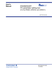
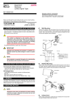
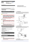
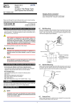
User’s
Manual
Model ML2
RS232C/RS485
Converter
IM 77J04L02-01E
Network Solutions Business Divisiion
2-9-32, Naka-cho Musashino-shi, Tokyo 180-8750 Japan
Phone: +81-422-52-7179 Facsimile: +81-422-52-6793
Please read through this User’s Manual before use for correct handling.
Please keep this User’s Manual for future reference.
IM 77J04L02-01E
1st Edition Sep. 2004 (YK)
● For RS-485, 2-wire or 4-wire can be selected by DIP switch. And
for 2-wire, On/Off of Echo back function can be selected by DIP
switch. (For 4-wire, be sure to set Echo back function at Off.)
● RS-485 line is internally equipped with 220⍀ terminating resistor.
With or without the resistor can be selected with the DIP switch.
● A corresponding communication speed can be changed to eight
stages and selected with the rotary switch.
(38400, 19200, 9600, 4800, 2400, 1200, 600, 300 bps)
1. CAUTIONARY NOTES FOR SAFE USE OF THE PRODUCT
This User’s Manual should be carefully read before installing and operating the product. The following symbol is used on the product and in
this manual to ensure safe use.
This symbol is displayed on the product when it is
necessary to refer to the User’s Manual for information on
personnel and instrument safety. This symbol is displayed
in the User’s Manual to indicate precautions for avoiding
danger to the operator, such as an electric shock.
4. MOUNTING METHODS
NOTE
Insert/pull out the main unit vertically to the surface of a
socket. Otherwise the terminals bend and it may cause a
bad contact.
The following symbols are used only in this manual.
IMPORTANT
4.1
Indicates that operating the hardware or software in a
particular manner may cause damage or result in a system
failure.
Wall Mounting
Unlock the stoppers (top and bottom), and pull out the main unit from
the socket. Then fix the socket on wall with two M4 mounting screws.
Insert the main unit to the socket and fix the main unit with stoppers
(top and bottom).
NOTE
Stopper
Draws attention to essential information for understanding
the operations and/or functions of the product.
Main unit
2. CHECKING PRODUCT SPECIFICATIONS AND PACKAGED ITEMS
Socket
(1) Checking the Model and Product Specifications
Mounting
screws
Check that the model and specifications indicated on the nameplate
attached to the side face of the main unit are as ordered.
(2) Packaged Items
Check that the packing carton contains the following items:
● ML2: 1
● Spacer (used for DIN rail mounting): 1
● Tag number label: 1 sheet
● User’s Manual (this manual: IM 77J04L02-01E): 1 copy
[Mounting Dimensions]
Pitch: 56 or more
5 or more
Socket
Unit: mm
2-⭋4.5 or 2-M4
(85)
3. GENERAL
This plug-in type RS-232C/RS-485 dual directional (half duplex) converter has two ports of RS-232C and RS-485. Between these two
ports, isolation, level conversion and active control of driver are performed. This converter is mainly used to connect RS-232C of personal
computer with the instruments equipped with RS-485.
40⫾0.2
(51)
Main Features and Functions
● Two modes (Auto and Manual) for Active control of RS-485 driver
can be selected with the DIP switch.
Auto: When start bit is detected on RS-232C side, the converter
makes RS-485 driver active.
Manual: Active control of RS-485 driver depends on RS (Request to
Send) of outer set instrument connected with RS-232C.
1
Note:
(1) More than 5 mm interval is
required for side-by-side
close mounting.
(2) Use the supplied spacer for
DIN rail mounting to keep 5
mm interval.
4.2
DIN Rail Mounting
6. EXTERNAL WIRING
Insert DIN rail into the upper portion of the DIN rail groove at rear of
socket of the converter and fix the converter to the DIN rail with slidelock at the lower of the converter.
WARNING
To avoid the risk of an electric shock, turn off the power
supply and use a tester or similar device to ensure that no
power is supplied to a cable to be connected, before carring
out wiring work.
Fit into here
DIN Rail
Wiring should be connected to the terminals on the socket of the
product. The terminals for external connections are of M3.5 screws.
Use crimp-on terminal lugs for connections to the terminals.
● Recommended cables: A nominal cross-sectional area of 0.5 mm2
or thicker (0.9 mm2 or thicker of multicore twisted pair cable with a
shield is recommended) for signal cables, and that of 1.25 mm2 or
thicker for power cables.
Push
DIN Rail
EW
A
VI
Spacer
VIEW A
(Rear of the socket)
RS-485
Communication
TML
6
5
4
3
Power Supply
GND
Slide-lock
6
4-wire Signal
SDA (–)
NC
2
SDB (+)
NC
3
RDA (–)
A (–)
4
RDB (+)
5
L+
2-wire Signal
1
B (+)
SG
7
N–
8
7
8
1
2
IMPORTANT
Spacer
4.3
● The power line and input/output signal lines should be
installed away from noise-generating sources. Other
wise accuracy cannot be guaranteed.
● The grounding resistance must be 100 Ω (JIS Class D
grounding). The length of the grounding cable should
be within 20 m. Directly connect the lead from the
ground terminal (terminal no. 6) of the product to the
ground. Do not carry out daisy-chained inter-ground
terminal wiring.
● Use of the product ignoring the specifications may
cause overheating or damage. Before turning on the
power, ensure the following:
(a) Power supply voltage and input signal value applied
to the product should meet the required
specifications.
(b) The external wiring to the terminals and wiring to
ground are as specifications.
● Do not operate the product in the presence of
flammable or explosive gases or vapors. To do so is
highly dangerous.
● The product is sensitive to static electricity; exercise
care in operating it. Before you operate the product,
touch a nearby metal part to discharge static electricity.
Using a Duct
When using a wiring duct, install the duct at least 20 mm away from the
top and bottom faces of the main unit.
5. INSTALLATION LOCATIONS
● Avoid the following environments for installation locations:
Areas with vibration, corrosive gases, dust, water, oil, solvents, direct sunlight, radiation, a strong electric field, and/or a strong
magnetic field
● If there is any risk of a surge being induced into the power line
and/or signal lines due to lightning or other factors, a dedicated
lightning arrester should be used as protection for both this unit
and a field-installed device.
2
IM 77J04L02-01E
1st Edition Sep.10, 2004-00
7. PART NAMES OF FRONT PANEL
9. EXPLANATION OF OPERATION
The product starts running immediately when the power is turned on;
however, it needs 10 to 15 minutes of warm-up before it meets the
specified performance.
RDY
9.1
(a) RS-232C → RS-485
Lit in green while the power is turned on
● When RS-485 Driver Active is in Auto
When start bit is detected on RS-232C side (Send Data becomes
logic 0), the converter makes RS-485 driver active, and transmits
data of RS-232C side to RS-485 side.
When Send Data of RS-232C becomes no data (logic 1), the converter starts timer of 10 bits*1 and maintains RS-485 driver active
until time-up. After time-up, the converter returns RS-485 driver
to passive to stop transmission.
● When RS-485 Driver Active is in Manual
When RS (Request to Send) of RS-232C side is turned on (logic
0), the converter makes RS-485 driver active and transmits data
of RS-232C side to RS-485 side. It maintains RS-485 driver active while RS (Request to Send) is turned on.
When RS (Request to Send) is turned off, the converter returns
RS-485 driver to passive to stop transmission.
Lit in green when data is received in
RXD of RS-232C side
SD/RD
DRIVER Lit in green while the driver is
ACTIVE active
ROTARY SWITCH
Set the switch in accordance with communication
speed.
DIP SWITCH
Set the switch in accordance with each setting.
12 3456
ON
(b) RS-485 → RS-232C
Left: OFF
Right: ON
● When start bit (logic 0) is detected on RS-485 side, the converter
turns off CS (Clear to Send) of RS-232C side and transmits data
of RS-485 side to RD (Receive Data) of RS-232C side.
When data of RS-485 side becomes logic 1, the converter starts
timer of 10 bits*1 and maintains CS (Clear to Send) of RS-232C
side off until time-up. After time-up, the converter turns on CS
(Clear to Send) to stop transmission.
*1: Equivalent to 10 bits of communication speed set to the
converter.
RS-232C CONNECTOR
D-sub 9-pin connector (male)
8. EXAMPLE OF USAGE
● 4-wire
9.2
RS-485
1
2
3
4
5
SDA (-)
SDB (+)
RDA (-)
RDB (+)
SG
RS-232C
(Straight
Cable)
6 8 7
RDA(-)
RDB(+)
SDA(-)
SDB(+)
SG
RS-232C → RS-485
When active control of RS-485 driver is set to Auto, RS-485 driver
is in active state for elapsed time of 10 bits after RS-232C data
becomes none. During this interim, even if RS-485 having quick
response generates signal, RS232C/RS485 converter cannot ensure transmit signal. Example of counterplan against this state is
as mentioned below:
Example 1
Set the active control of RS-485 driver to Manual. At upper computer side connected with RS-232C, make synchronization of
data transmit and RS (Request to Send). When data transmit
completes, make RS-485 driver passive immediately.
Example 2
Set the communication setting time of RS232C/RS485 converter
shorter (faster) than data transmit speed.
However, in this case, fail safe circuit should be included in every
function of RS-485 connected with this converter. (In order to
make the fail safe circuit of communication opponent recognize
the disabled state after timer cut off.)
When data from RS-485 instrument is transmitted to RS-232C,
because CS (Clear to Send) turns on during data transmission,
upper computer connected with RS-232C should incorporate
communication sequence so as to enter transmit state after receiving data up to the end.
Upper Computer
Power Supply
To other RS-485 instrument
● 2-wire
RS-485
ML2
A(-)
B(+)
SG
3 A (-)
4 B (+)
5 SG
RS-232C
(Straight
Cable)
6 8 7
Counterplan for Connections to RS-485 Instruments Having Quick Response
When starting up system or when newly adding connection of instruments, if RS-485 response is quick, communication may sometimes
not be carried out smoothly.
ML2
RDA(-)
RDB(+)
SDA(-)
SDB(+)
SG
Signal Transmit Mode (Start bit detection timer
mode)
Upper Computer
Power Supply
A(-)
B(+)
SG
To other RS-485 instrument
3
IM 77J04L02-01E
1st Edition Sep.10, 2004-00
10. SWITCH SETTING
This converter has the following five setting elements.
Communication speed (Baud rate)
Selection of 2-wire/4-wire
Selection of Auto/Manual of RS-485 driver active
Selection of with/without the terminating resistor
Selection of On/Off of echo back function
10.1 Setting Each Section
Setting of Rotary Switch
Set the rotary switch according to communication speed.
The table below shows switch position corresponding to communication speed (bps). When shipping from the factory, the rotary
switch position is set to 5.
Setting of Rotary Switch
No.
0
1
2
3
4
5
6
7
Transmit
Speed (bps)
300
600
1200
2400
4800
9600
19200
38400
Timer
(ms)
33.3
16.7
8.33
4.17
2.08
1.04
0.52
0.26
Setting of DIP Switches (No.1 to No.6)
No.1 and No.2: Select 2-wire or 4-wire. (Factory-set default: On, 2wire)
No.3: Selects Auto/Manual of RS-485 driver active. (Factory-set default: Off, Auto)
Set the circuit that controls RS-485 driver active. Select Auto or
Manual according to the communication program of host device
connected with RS-232C connector.
No.4: Select with or without the terminating resistor. (Factory-set default: On)
When this converter is in the terminus of RS-485 line, set it to On
so as that the terminating resistor would become effective. In
most cases, the converter is used as terminus. However, if not,
set it to Off.
No.5: Select On/Off of echo back. (Factory-set default: Off)
If used for 4-wire, be sure to set the switch to Off.
No.6: Be sure to set the switch to Off.
Setting of DIP Switch
No.
1
2
3
4
5
6
Setting
OFF
ON
2-wire/4-wire
4-wire
2-wire
Driver active
Terminating resistor
Echo back
Fixed to OFF
Auto
Without
OFF
OFF
Manual
With
ON
-
4
IM 77J04L02-01E
1st Edition Sep.10, 2004-00