Download Manual Supplement
Transcript
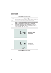
Manual Supplement Manual Title: 1652C/1653B/1654B Users Supplement Issue: Print Date: September 2010 Issue Date: Revision/Date: Page Count: 4 2/15 3 This supplement contains information necessary to ensure the accuracy of the above manual. This manual is distributed as an electronic manual on the following CD-ROM: CD Title: CD Rev. & Date: CD PN: © 2010-2015 Fluke Corporation. All rights reserved. 1652C/1653B/1654B 9/2010 3798444 1652C/1653B/1654B Users Manual Supplement Change #1, 56800 On page 3, add the following bullet: • Do not use in CAT III or CAT IV environments without the protective cap installed. The protective cap decreases the possibility of arc flash caused by short circuits. On page 6, under Operating the Tester Using the Rotary Switch, add the following: Warning Do not use in CAT III or CAT IV environments without the protective cap installed. The protective cap decreases the exposed probe metal to <4mm. This decreases the possibility of arc flash from short circuits. On page 45, under General Specifications, add the following to the Safety section: Complies with EN/IEC 61010-031:2002+A1:2008. Change #2, 59912 On page 18, Table 8, replace row 2 with: Extended documentation mode. Simultaneously press the Power button and the Up cursor key (1654B only). Additional information is stored with an insulation test result (P/P, P/N, P/E, N/E) and with a continuity test result (R1+R2, R2, r1, r2, rn). On page 20, replace the Extended Documentation Mode section with: Extended Documentation Mode In the Extended Documentation mode (1654B only), the Tester stores the measurement result with the measurement location: P/P, P/N, P/E or N/E. You can select the information before or after the measurement with . The definitions are: P/P = L, P/N = L-N, P/E = L-PE, N/E = NPE. On page 22, replace Extended Documentation Mode section with: Extended Documentation Mode In the Extended Documentation mode (1654B only), the Tester stores the measurement result with the measurement location: R1+R2, R2, r1, r2 or rn. You can select the information before or after the measurement with . The definitions are: R1+R2 = Rx1/2, R2 = R/2, r1 = x1, r2 = /2,rn = x5. On pages 24 and 26, replace step 4 with: 4. For the 1654B only, press to select between and m resolution for the test results. The m resolution test takes between 30 and 60 seconds to complete. On page 29 replace the last two bullets in step 4 and the Note with: 1654B only: 10/11 • – Smooth-DC current to test type B RCD • – Delayed response to S-type B (time delayed smooth-DC current RCD) 1 Manual Supplement 1652C/1653B/1654B Users Note For RCD type B () or S-type B ( ), you must test with both phase settings and measure the trip current. On page 33, replace the last two bullets in step 3: 1654B only: • – Smooth-DC current to test type B RCD • – Delayed response to S-type B (time delayed smooth-DC current RCD) On page 52, replace the second Table with: Range Accuracy[1] Resolution 10 Ω[2} 0.001 Ω 20 Ω 0.01 Ω 200 Ω 0.1 Ω 2000 Ω 1Ω Hi Current m mode: ±(2 % + 15 digits) No Trip mode: ±(3 % + 6 digits) Hi Current mode: ±(2 % + 4 digits) No Trip mode: ±(3 %) Hi Current mode: ±(2 %) ±6 %[3] Notes [1] Valid for resistance of neutral circuit <20 Ω and up to a system phase angle of 30 °. Test leads must be zeroed before testing. [2] 1654B only. [3] Valid for mains voltage >200 V. Change #3, 464 On page 3, add the following to the Symbols table: Conforms to relevant South Korean EMC Standards. On page 45, under General Specifications remove EMC and add: Electromagnetic Environment Electromagnetic Compatibility IEC 61326-1: Portable Applies to use in Korea only. Class A Equipment (Industrial Broadcasting & Communication Equipment) This product meets requirements for industrial (Class A) electromagnetic wave equipment and the seller or user should take notice of it. This equipment is intended for use in business environments and is not to be used in homes. 2 2/15 1652C/1653B/1654B Users Manual Supplement Change #4, 114 On page 32, under the note, remove the following sentence: Type A and type B RCDs do not have the 1000 mA option available. On page 32, under To measure RCD tripping current, replace step 2 with: Press to select the RCD current rating (10, 30, 100, 300, or 500 mA). If the RCD has a special nominal current setting other than the standard options, 10, 30, 100, 300, 500 mA, you can use a custom setting with the VAR mode. 2. On page 54, replace the Tripping Speed Test (ΔT) table with: Tripping Speed Test (ΔT) Test Function RCD Current Selection 10 mA 30 mA 100 mA[1] 300 mA[1] 500 mA[1] 1000 mA[2] var[3] x ½, 1 √ √ √ x5 √ √ √ Ramp √ √ √ Auto √ √ √ √ √ √ √ √ Notes Mains voltage 100 V – 265 V ac, 50/60 Hz [1] Type B RCDs require mains voltage range of 195 V – 265 V. [2] Type AC RCDs only. [3] Type A RCDs are limited to 700 mA, not available for Type B RCDs. 2/15 3 √ √


