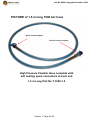
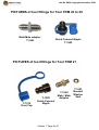
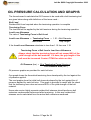
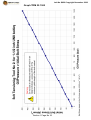
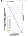
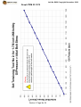
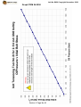
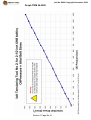
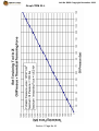
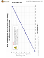
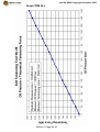
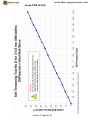
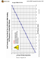
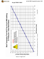
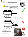
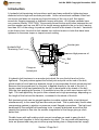
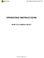
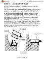
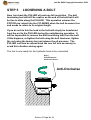
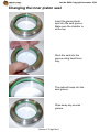
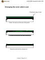
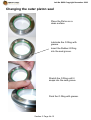
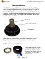
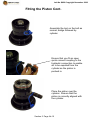
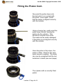
1
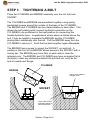
Job No Q620 Copyright November 2006
Hydraulic Bolt Tensioning
Equipment, Health & Safety,
Operating and Maintenance
Instruction Manual
Customer Name
Customer Order No
Titan Job No
Date
TITAN Technologies Korea
Q620
November 2006
Job No Q620 Copyright November 2006
Copyright Statement
This Health & Safety, Operating and Maintenance
Manual has been prepared by the company, Titan
Technologies Inc. All of the material in this manual is
the property of the company and is subject to copyright.
No part of this manual may be copied or reproduced
without the prior written consent of the company.
Further copies of this manual may be purchased from
Titan Technologies Inc.
Job No Q620 Copyright November 2006
CONTENTS
1 - Technical Information
List of equipment supplied
Technical Information
Test Certificate
Parts Lists for each Tool Size
Oil Pressure Calculation
Table of Oil Pressure Graphs
Oil Pressure Graphs
Section 1
Page 2
Page 3
Page 5
Page 6-27
Page 28
Page 29
Page 30-49
2 - Health and Safety
Important Notice
Working with Quick Connectors
Working with Hoses
Working with Bolt Tensioning Tools
Section 2
Page 2
Page 3
Page 4
Page 5
3 - Operating Instructions
How to tighten a bolt Steps 1 to 16
How to loosen a bolt Steps 1 to 14
Returning the Pistons
Section 3
Page 1
Page 25
Page 42
4 - Simultaneous Bolt Tensioning
Connecting tools together for simultaneous operation
Section 4
Page 2
5 - Maintenance Instructions
Introduction
Changing the Seals
Fitting the Piston
Energising the Seals
Fitting the Quick Connectors
Removing and Fitting the Bridge
Section 5
Page 2
Page 3
Page 14
Page 17
Page 18
Page 20
Job No Q620 Copyright November 2006
SECTION 1
TECHNICAL INFORMATION
Section 1 Page No 1
Job No Q620 Copyright November 2006
Technical Information
Summary of Equipment Supplied
2 off
6 off
4 off
6 off
4 off
10 off
4 off
4 off
4 off
4 off
4 off
8 off
4 off
5 off
5 off
5 off
5 off
5 off
5 off
5 off
5 off
4 off
4 off
4 off
4 off
4 off
4 off
4 off
1 off
1 off
Tool No 27 for 4 inch UN8 bolting
Tool No 27 for 3-3/4 inch UN8 bolting
Tool No 26 for 3-1/2 inch UN8 bolting
Tool No 25 for 3 inch UN8 bolting
Tool No 25 for 2-3/4 inch UN8 bolting
Tool No 24 for 2-1/2 inch UN8 bolting
Tool No 24 for 2-1/4” UN8 bolting
Tool No 23 for 1-7/8 inch UN8 bolting
Tool No 23 for 1-5/8 inch UN8 bolting
Tool No 22 for 1-1/2 inch UN8 bolting
Tool No 21 for 1-1/8” UN8 bolting
Tool No 21 for 1 inch UNC bolting
Tool No 21 fore 7/8” UNC bolting
Link Hose 1.5 m long
Seal Kit for Tool No 27
Seal Kit for Tool No 26
Seal Kit for Tool No 25
Seal Kit for Tool No 24
Seal Kit for Tool No 23
Seal Kit for Tool No 22
Seal Kit for Tool No 21
Tommy Bar 20 mm dia
Tommy Bar 16 mm dia
Tommy Bar 14 mm dia
Tommy Bar 12 mm dia
Tommy Bar 10 mm dia
Tommy Bar 8 mm dia
Tommy Bar 6 mm dia
Pressure Test Certificate
Operating Manual
T-4000-T27
T-3750-T27
T-3500-T26
T-3000-T25
T-2750-T25
T-2500-T24
T-2250-T24
T-1875-T23
T-1625-T23
T-1500-T22
T-1125-T21
T-1000-T21
T-0875-T21
T-1540-1.5
T-SK-T27
T-SK-T26
T-SK-T25
T-SK-T24
T-SK-T23
T-SK-T22
T-SK-T21
T-TB-20
T-TB-16
T-TB-14
T-TB-12
T-TB-10
T-TB-8
T-TB-6
All above equipment designated for 1500 bar maximum working pressure
Section 1 Page No 2
Job No Q620 Copyright November 2006
Technical Information
Tool No 21
Pressure Area
Maximum Working Pressure
Maximum Load
1,555 mm2
1500 bar
233 kN
Tool No 22
Pressure Area
Maximum Working Pressure
Maximum Load
2,884 mm2
1500 bar
433 kN
Tool No 23
Pressure Area
Maximum Working Pressure
Maximum Load
5,271 mm2
1500 bar
791 kN
Tool No 24
Pressure Area
Maximum Working Pressure
Maximum Load
8,445 mm2
1500 bar
1,267 kN
Tool No 25
Pressure Area
Maximum Working Pressure
Maximum Load
12,197 mm2
1500 bar
1,830 kN
Tool No 26
Pressure Area
Maximum Working Pressure
Maximum Load
16,682 mm2
1500 bar
2,502 kN
Tool No 27
Pressure Area
Maximum Working Pressure
Maximum Load
17,530 mm2
1500 bar
2,629 kN
Section 1 Page No 3
Job No Q620 Copyright November 2006
Technical Information
Fatigue Life
The Puller of the Bolt Tensioning Tool is subject to fatigue loading during
normal operation of the equipment. The Pullers provided have a fatigue
life of between 10,000 and 20,000 cycles at full operating pressure.
Provision should be made to replace the Pullers at 10,000 pressure
cycles.
Section 1 Page No 4
Job No Q620 Copyright November 2006
Test Certificate
Section 1 Page No 5
Job No Q620 Copyright November 2006
PARTS LIST FOR TOOL TRM 21 for 7/8 inch UNC
Part No
T-3650-00
T-3651-00
T-1739-00
T-0417-00
T-3545-00
T-BRSDP-M506
T-SK-T21
T-IR-T21
T-1502
T-1524
T-1533
T-1510
T-L1-T21
Description
Quantity
No 21 Cylinder Body
No 21 Piston
No 21 Puller for 7/8 inch UNC
No 21 Socket for 7/8 inch
No 21 Bridge for ¾” and 7/8 inch
Bridge Retaining Screw
Seal Kit for Tool No 21
Red Plastic Stroke Indicator for Tool No 21
Quick connect nipple
Male/male adaptor
Bonded Washer Seal
Plastic dust cap for nipple
Label for Tool No 21
Hydraulic Cylinder No 21
1
1
1
1
1
2
1
1
1
1
1
1
1
7/8” UNC Puller
T-1739-00
3/4 inch and 7/8 inch Bridge
T-3545-00
7/8” Socket
T-0417-00
Section 1 Page No 6
Job No Q620 Copyright November 2006
PARTS LIST FOR TOOL TRM 21 for 1 inch UNC
Part No
T-3650-00
T-3651-00
T-1738-00
T-0398-00
T-3546-00
T-BRSDP-M506
T-SK-T21
T-IR-T21
T-1502
T-1524
T-1533
T-1510
T-L1-T21
Description
Quantity
No 21 Cylinder Body
No 21 Piston
No 21 Puller for 1 inch UNC
No 21 Socket for 1 inch
No 21 Bridge for 1 inch and 1-1/8 inch
Bridge Retaining Screw
Seal Kit for Tool No 21
Red Plastic Stroke Indicator for Tool No 21
Quick connect nipple
Male/male adaptor
Bonded Washer Seal
Plastic dust cap for nipple
Label for Tool No 21
Hydraulic Cylinder No 21
1
1
1
1
1
2
1
1
1
1
1
1
1
1” UNC Puller
T-1738-00
1 inch and 1-1/8 inch Bridge
T-3546-00
1” Socket
T-0398-00
Section 1 Page No 7
Job No Q620 Copyright November 2006
PARTS LIST FOR TOOL TRM 21 for 1-1/8 inch UN8
Part No
T-3650-00
T-3651-00
T-1737-01
T-0399-02
T-3546-00
T-BRSDP-M506
T-SK-T21
T-IR-T21
T-1502
T-1524
T-1533
T-1510
T-L1-T21
Description
Quantity
No 21 Cylinder Body
No 21 Piston
No 21 Puller for 1-1/8 inch UN8
No 21 Socket for 1-1/8 inch
No 21 Bridge for 1 inch and 1-1/8 inch
Bridge Retaining Screw
Seal Kit for Tool No 21
Red Plastic Stroke Indicator for Tool No 21
Quick connect nipple
Male/male adaptor
Bonded Washer Seal
Plastic dust cap for nipple
Label for Tool No 21
Hydraulic Cylinder No 21
1
1
1
1
1
2
1
1
1
1
1
1
1
1-1/8” UN8 Puller
T-1737-01
1 inch and 1-1/8 inch Bridge
T-3546-00
1-1/8” Socket
T-0399-02
Section 1 Page No 8
Job No Q620 Copyright November 2006
PARTS LIST FOR TOOL TRM 21
Piston
T-3651-00
Bonded Washer Seal
T-1533
Quick Connect Nipple
T-1502
Cylinder Body
T-3650-00
Plastic Dust Cap
T-1510
Male/male adaptor
T-1524
Cylinder Assembly No 21
Stroke Indicator
T-IR-T21
Seal Kit
T-SK-T21
Section 1 Page No 9
Job No Q620 Copyright November 2006
PARTS LIST FOR TOOL TRM 22 for 1-1/2 inch UN8
Part No
T-1985-00
T-1998-00
T-0589-02
T-0816-01
T-0592-03
T-BRSDP-M510
T-SK-T22
T-IR-T22
T-1502
T-1503
T-1510
T-L1-T22
Description
Quantity
No 22 Cylinder Body
No 22 Piston
No 22 Puller for 1-1/2 inch UN8
No 22 Socket for 1-1/2 inch
No 22 Bridge for 1-3/8 inch and 1-1/2 inch
Bridge Retaining Screw
Seal Kit for Tool No 22
Red Plastic Stroke Indicator for Tool No 22
Quick connect nipple
Male/male adaptor
Plastic dust cap for nipple
Label for Tool No 22
Hydraulic Cylinder No 22
1
1
1
1
1
2
1
1
1
1
1
1
1-1/2” UN8 Puller
T-0589-02
1-3/8 inch and 1-1/2 inch Bridge
T-0592-03
Section 1 Page No 10
1-1/2” Socket
T-0816-01
Job No Q620 Copyright November 2006
PARTS LIST FOR TOOL TRM 22
Quick Connect Nipple
T-1502
Piston
T-1998-00
Cylinder Body
T-1985-00
Male/male adaptor
T-1503
Plastic Dust Cap
T-1510
Cylinder Assembly No 22
Stroke Indicator
T-IR-T22
Seal Kit
T-SK-T22
Section 1 Page No 11
Job No Q620 Copyright November 2006
PARTS LIST FOR TOOL TRM 23 for 1-5/8 inch UN8
Part No
T-1989-01
T-0622-01
T-0809-01
T-0813-01
T-0804-02
T-BRSDP-M512
T-SK-T23
T-IR-T23
T-1502
T-1503
T-1510
T-L1-T23
Description
Quantity
No 23 Cylinder Body
No 23 Piston
No 23 Puller for 1-5/8 inch UN8
No 23 Socket for 1-5/8 inch
No 23 Bridge for 1-5/8 inch and 1-3/4
Bridge Retaining Screw
Seal Kit for Tool No 23
Red Plastic Stroke Indicator for Tool No 23
Quick connect nipple
Male/male adaptor
Plastic dust cap for nipple
Label for Tool No 23
Hydraulic Cylinder No 23
1
1
1
1
1
2
1
1
1
1
1
1
1-5/8” UN8 Puller
T-0809-01
1-5/8 inch and 1-3/4 inch Bridge
T-0804-02
Section 1 Page No 12
1-5/8” Socket
T-0813-01
Job No Q620 Copyright November 2006
PARTS LIST FOR TOOL TRM 23 for 1-7/8 inch UN8
Part No
T-1989-01
T-0622-01
T-0807-01
T-0811-01
T-0805-03
T-BRSDP-M512
T-SK-T23
T-IR-T23
T-1502
T-1503
T-1510
T-L1-T23
Description
Quantity
No 23 Cylinder Body
No 23 Piston
No 23 Puller for 1-7/8 inch UN8
No 23 Socket for 1-7/8 inch
No 23 Bridge for 1-7/8 inch and 2 inch
Bridge Retaining Screw
Seal Kit for Tool No 23
Red Plastic Stroke Indicator for Tool No 23
Quick connect nipple
Male/male adaptor
Plastic dust cap for nipple
Label for Tool No 23
Hydraulic Cylinder No 23
1
1
1
1
1
2
1
1
1
1
1
1
1-7/8” UN8 Puller
T-0807-01
1-7/8 inch and 2 inch Bridge
T-0805-03
1-7/8” Socket
T-0811-01
Section 1 Page No 13
Job No Q620 Copyright November 2006
PARTS LIST FOR TOOL TRM 23
Quick Connect Nipple
T-1502
Piston
T-0622-01
Cylinder Body
T-1989-01
Male/male adaptor
T-1503
Plastic Dust Cap
T-1510
Cylinder Assembly No 23
Stroke Indicator
T-IR-T23
Seal Kit
T-SK-T23
Section 1 Page No 14
Job No Q620 Copyright November 2006
PARTS LIST FOR TOOL TRM 24 for 2-1/4 inch UN8
Part No
T-3021-00
T-3022-01
T-0682-00
T-3464-00
T-3682-00
T-BRSDP-M512
T-SK-T24
T-IR-T24
T-1502
T-1503
T-1510
T-L1-T24
Description
Quantity
No 24 Cylinder Body
No 24 Piston
No 24 Puller for 2-1/4 inch UN8
No 29 Socket for 2-1/4 inch
No 24 Bridge for 2-1/4 inch
Bridge Retaining Screw
Seal Kit for Tool No 24
Red Plastic Stroke Indicator for Tool No 24
Quick connect nipple
Male/male adaptor
Plastic dust cap for nipple
Label for Tool No 24
Hydraulic Cylinder No 24
1
1
1
1
1
3
1
1
1
1
1
1
2-1/4” UN8 Puller
T-0682-00
2-1/4” Bridge
T-3682-00
2-1/4” Socket
T-3464-00
Section 1 Page No 15
Job No Q620 Copyright November 2006
PARTS LIST FOR TOOL TRM 24 for 2-1/2 inch UN8
Part No
T-3021-00
T-3022-01
T-0681-00
T-3024-00
T-3223-01
T-BRSDP-M512
T-SK-T24
T-IR-T24
T-1502
T-1503
T-1510
T-L1-T24
Description
Quantity
No 24 Cylinder Body
No 24 Piston
No 24 Puller for 2-1/2 inch UN8
No 24 Socket for 2-1/2 inch
No 24 Bridge for 2-1/2 inch
Bridge Retaining Screw
Seal Kit for Tool No 24
Red Plastic Stroke Indicator for Tool No 24
Quick connect nipple
Male/male adaptor
Plastic dust cap for nipple
Label for Tool No 24
2-1/2” UN8 Puller
T-0681-00
Hydraulic Cylinder No 24
2-1/2” Socket
T-3024-00
2-1/2” Bridge
T-3223-01
Section 1 Page No 16
1
1
1
1
1
3
1
1
1
1
1
1
Job No Q620 Copyright November 2006
PARTS LIST FOR TOOL TRM 24
Quick Connect Nipple
T-1502
Piston
T-3022-01
Cylinder Body
T-3021-00
Male/male adaptor
T-1503
Plastic Dust Cap
T-1510
Cylinder Assembly No 24
Stroke Indicator
T-IR-T24
Seal Kit
T-SK-T24
Section 1 Page No 17
Job No Q620 Copyright November 2006
PARTS LIST FOR TOOL TRM 25 for 2-3/4 inch UN8
Part No
T-1654A-01
T-1654B-01
T-0831-01
T-1976-00
T-1975-01
T-BRSDP-M512
T-SK-T25
T-IR-T25
T-1502
T-1503
T-1510
T-L1-T25
Description
Quantity
No 25 Cylinder Body
No 25 Piston
No 25 Puller for 2-3/4 inch UN8
No 25 Socket for 2-3/4 inch
No 25 Bridge for 2-3/4 inch
Bridge Retaining Screw
Seal Kit for Tool No 25
Red Plastic Stroke Indicator for Tool No 25
Quick connect nipple
Male/male adaptor
Plastic dust cap for nipple
Label for Tool No 25
2-3/4” UN8 Puller
T-0831-01
Hydraulic Cylinder No 25
2-3/4” Socket
T-1976-00
2-3/4” Bridge
T-1975-01
Section 1 Page No 18
1
1
1
1
1
3
1
1
1
1
1
1
Job No Q620 Copyright November 2006
PARTS LIST FOR TOOL TRM 25 for 3 inch UN8
Part No
T-1654A-01
T-1654B-01
T-0830-01
T-0353-02
T-1977-00
T-BRSDP-M512
T-SK-T25
T-IR-T25
T-1502
T-1503
T-1510
T-L1-T25
Description
Quantity
No 25 Cylinder Body
No 25 Piston
No 25 Puller for 3 inch UN8
No 25 Socket for 3 inch
No 25 Bridge for 3 inch
Bridge Retaining Screw
Seal Kit for Tool No 25
Red Plastic Stroke Indicator for Tool No 25
Quick connect nipple
Male/male adaptor
Plastic dust cap for nipple
Label for Tool No 25
3” UN8 Puller
T-0830-01
Hydraulic Cylinder No 25
3” Socket
T-0353-02
3” Bridge
T-1977-00
Section 1 Page No 19
1
1
1
1
1
3
1
1
1
1
1
1
Job No Q620 Copyright November 2006
PARTS LIST FOR TOOL TRM 25
Quick Connect Nipple
T-1502
Piston
T-1654A-01
Cylinder Body
T-1654B-01
Male/male adaptor
T-1503
Plastic Dust Cap
T-1510
Cylinder Assembly No 25
Stroke Indicator
T-IR-T25
Seal Kit
T-SK-T25
Section 1 Page No 20
Job No Q620 Copyright November 2006
PARTS LIST FOR TOOL TRM 26 for 3-1/2 inch UN8
Part No
Description
T-0737-00
T-0729-00
T-0727-01
T-0732-00
T-0736-00
T-BRSDP-M612
T-SK-T26
T-IR-T26
T-1502
T-1503
T-1510
T-L1-T26
Quantity
Cylinder Body
Piston
Puller No 26 for 3-1/2 inch UN8
Socket for 3-1/2 inch
Bridge for 3-1/2 inch
Bridge retaining screw
Seal Kit for Tool No 26
Red Plastic Stroke Indicator for Tool No 26
Quick connect nipple
Male/male adaptor
Plastic dust cap for nipple
Label for Tool No 26
Hydraulic Cylinder No 26
3-1/2 inch Bridge
T-0736-00
Section 1 Page No 21
3-1/2” UN8 Puller
T-0727-01
3-1/2 inch Socket
T-0732-00
1
1
1
1
1
3
1
1
1
1
1
1
Job No Q620 Copyright November 2006
PARTS LIST FOR TOOL TRM 26
Quick Connect Nipple
T-1502
Piston
T-0737-00
Cylinder Body
T-0729-00
Male/male adaptor
T-1503
Plastic Dust Cap
T-1510
Cylinder Assembly
Stroke Indicator
T-IR-T26
Seal Kit
T-SK-T26
Section 1 Page No 22
Job No Q620 Copyright November 2006
PARTS LIST FOR TOOL TRM 27 for 3-3/4 inch UN8
Part No
Description
T-3093-00
T-3094-00
T-3091-00
T-3098-00
T-3099-00
T-BRSDP-M612
T-SK-T27
T-IR-T27
T-1502
T-1503
T-1510
T-L1-T27
Quantity
Cylinder Body
Piston
Puller No 27 for 3-3/4 inch UN8
Socket for 3-3/4 inch
Bridge for 3-3/4 inch
Bridge retaining screw
Seal Kit for Tool No 27
Red Plastic Stroke Indicator for Tool No 27
Quick connect nipple
Male/male adaptor
Plastic dust cap for nipple
Label for Tool No 27
Hydraulic Cylinder No 27
3-3/4 inch Bridge
T-3099-00
Section 1 Page No 23
3-3/4” UN8 Puller
T-3091-00
3-3/4 inch Socket
T-3098-00
1
1
1
1
1
3
1
1
1
1
1
1
Job No Q620 Copyright November 2006
PARTS LIST FOR TOOL TRM 27 for 4 inch UN8
Part No
Description
T-3093-00
T-3094-00
T-3092-00
T-3096-00
T-3609-00
T-BRSDP-M612
T-SK-T27
T-IR-T27
T-1502
T-1503
T-1510
T-L1-T27
Quantity
Cylinder Body
Piston
Puller No 27 for 4 inch UN8
Socket for 4 inch
Bridge for 4 inch
Bridge retaining screw
Seal Kit for Tool No 27
Red Plastic Stroke Indicator for Tool No 27
Quick connect nipple
Male/male adaptor
Plastic dust cap for nipple
Label for Tool No 27
Hydraulic Cylinder No 27
4 inch Bridge
T-3609-00
4” UN8 Puller
T-3092-00
4 inch Socket
T-3096-00
Section 1 Page No 24
1
1
1
1
1
3
1
1
1
1
1
1
Job No Q620 Copyright November 2006
PARTS LIST FOR TOOL TRM 27
Quick Connect Nipple
T-1502
Piston
T-3094-00
Cylinder Body
T-3093-00
Male/male adaptor
T-1503
Plastic Dust Cap
T-1510
Cylinder Assembly No 27
Stroke Indicator
T-IR-T27
Seal Kit
T-SK-T27
Section 1 Page No 25
Job No Q620 Copyright November 2006
PICTURE of 1.5 m long 1500 bar hose
Quick Connect Nipple
Quick Connect Coupling
High Pressure Flexible Hose complete with
self sealing quick connectors at each end
1.5 m Long Part No T-1540-1.5
Section 1 Page No 26
Job No Q620 Copyright November 2006
PICTURES of tool fittings for Tool TRM 22 to 29
Male/Male adaptor
T-1503
Quick Connect Nipple
T-1502
PICTURES of tool fittings for Tool TRM 21
T-1510
Dust Cap
T-1502
Quick Connect
Nipple
T-1524
Male / Male
Adaptor
Section 1 Page No 27
T-1533
Bonded
Washer
Seal
Job No Q620 Copyright November 2006
OIL PRESSURE CALCULATION AND GRAPHS
The formula used to calculate the Oil Pressure to be used with a bolt tensioning tool
are given below along with definitions of the terms used :Bolt Load
Residual Bolt Load required when the tensioning operation is complete
Tensioning Force
The load that will be applied by the bolt tensioner during the tensioning operation
Load Loss Allowance
The ratio of Tensioning Force to Bolt Load
Load Loss Allowance = Tensioning Force = 1.01 + Bolt Diameter
Bolt Load
Grip Length
If the Load Loss Allowance calculates to less than 1.10 then use 1.10.
Tensioning Force = Bolt Load x Load Loss Allowance
Always check that the tensioning force will not exceed 90% of the
yield strength of the bolt material. If it does, the grip length of the
bolt must be increased. Contact TITAN for advice on this.
Oil Pressure (bar) = 10 x Tensioning Force (Newtons)
Tool Pressure Area (mm2)
Oil pressure graphs are provided for each bolt size.
One graph shows the theoretical tensioning force developed by the tool against the
oil pressure applied.
The next graphs show the initial bolt stress developed by the tool against the oil
pressure applied for each bolt size. This graph is provided to assist with the check
that the tensioning force does not exceed 90% of the yield strength of the bolt
material.
Users who require highly accurate residual bolt stresses should perform a bolt
extension measurement before and after tensioning. In this way residual bolt
stresses can be calculated from the actual bolt extensions measured.
Section 1 Page No 28
Job No Q620 Copyright November 2006
TABLE OF OIL PRESSURE GRAPHS
Tool No 21
Graph No 21.L
Graph No 21.0875
Graph No 21.1000
Graph No 21.1250
Oil Pressure v Theoretical Load
Oil Pressure v Initial Bolt Stress 7/8 inch bolts
Oil Pressure v Initial Bolt Stress 1 inch bolts
Oil Pressure v Initial Bolt Stress 1-1/8 inch bolts
Tool No 22
Graph No 22.L
Graph No 22.1500
Oil Pressure v Theoretical Load
Oil Pressure v Initial Bolt Stress 1-1/2 inch bolts
Tool No 23
Graph No 23.L
Graph No 23.1625
Graph No 23.1875
Oil Pressure v Theoretical Load
Oil Pressure v Initial Bolt Stress 1-5/8 inch bolts
Oil Pressure v Initial Bolt Stress 1-7/8 inch bolts
Tool No 24
Graph No 24.L
Graph No 24.2250
Graph No 24.2500
Oil Pressure v Theoretical Load
Oil Pressure v Initial Bolt Stress 2-1/4 inch bolts
Oil Pressure v Initial Bolt Stress 2-1/2 inch bolts
Tool No 25
Graph No 25.L
Graph No 25.2750
Graph No 25.3000
Oil Pressure v Theoretical Load
Oil Pressure v Initial Bolt Stress 2-3/4 inch bolts
Oil Pressure v Initial Bolt Stress 3 inch bolts
Tool No 26
Graph No 26.L
Graph No 26.3500
Oil Pressure v Theoretical Load
Oil Pressure v Initial Bolt Stress 3-1/2 inch bolts
Tool No 27
Graph No 27.L
Graph No 27.3750
Graph No 27.4000
Oil Pressure v Theoretical Load
Oil Pressure v Initial Bolt Stress 3-3/4 inch bolts
Oil Pressure v Initial Bolt Stress 4 inch bolts
Section 1 Page No 29
Job No Q620 Copyright November 2006
Graph TRM 21.L
Section 1 Page No 30
Job No Q620 Copyright November 2006
Graph TRM 21.0875
Section 1 Page No 31
Job No Q620 Copyright November 2006
Graph TRM 21.1000
Section 1 Page No 32
Job No Q620 Copyright November 2006
Graph TRM 21.1125
Section 1 Page No 33
Job No Q620 Copyright November 2006
Graph TRM 22.L
Section 1 Page No 34
Job No Q620 Copyright November 2006
Graph TRM 22.1500
Section 1 Page No 35
Job No Q620 Copyright November 2006
Graph TRM 23.L
Section 1 Page No 36
Job No Q620 Copyright November 2006
Graph TRM 23.1625
Section 1 Page No 37
Job No Q620 Copyright November 2006
Graph TRM 23.1875
Section 1 Page No 38
Job No Q620 Copyright November 2006
Graph TRM 24.L
Section 1 Page No 39
Job No Q620 Copyright November 2006
Graph TRM 24.2250
Section 1 Page No 40
Job No Q620 Copyright November 2006
Graph TRM 24.2500
Section 1 Page No 41
Job No Q620 Copyright November 2006
Graph TRM 25.L
Section 1 Page No 42
Job No Q620 Copyright November 2006
Graph TRM 25.2750
Section 1 Page No 43
Job No Q620 Copyright November 2006
Graph TRM 25.3000
Section 1 Page No 44
Job No Q620 Copyright November 2006
Graph TRM 26.L
Section 1 Page No 45
Job No Q620 Copyright November 2006
Graph TRM 26.3500
Section 1 Page No 46
Job No Q620 Copyright November 2006
Graph TRM 27.L
Section 1 Page No 47
Job No Q620 Copyright November 2006
Graph TRM 27.3750
Section 1 Page No 48
Job No Q620 Copyright November 2006
Graph TRM 27.4000
Section 1 Page No 49
Job No Q620 Copyright November 2006
SECTION 2
HEALTH & SAFETY
INSTRUCTIONS
Persons using hydraulic bolt tensioning tools must
read and understand this section before starting to
use the equipment. Your attention is particularly
drawn to the instructions in RED on Page 2 and Page 7
Important Notice
Page 2
Using the Quick Connectors
Page 3
Using the Hoses
Page 4
Using the Tools
Page 5
Section 2 Page No 1
Job No Q620 Copyright November 2006
HEALTH & SAFETY INSTRUCTIONS
THINK SAFETY
IMPORTANT NOTICE
Thank you for purchasing or renting your hydraulic bolt tensioning equipment from
TITAN. Bolt tensioning tools are very powerful and capable of inducing very high
bolt stresses. This equipment has been designed to give many years of safe
tightening of bolted connections when used in accordance with these instructions.
Persons using hydraulic bolt tensioning tools must be properly trained in the correct
use of the equipment and must take adequate steps to ensure their own safety,
and the Health and Safety of others working in the area where bolt tensioning
operations are being performed. TITAN will be pleased to quote for the provision
of training courses either at its base or on site anywhere in the world.
Operators must read all of this instruction and maintenance manual before
attempting to use the equipment. Do not use the equipment if you are not already
an experienced user of hydraulic bolt tensioning tools or if you have not already
received proper training. Your attention is particularly drawn to the notes in RED.
Tightening a bolt with a hydraulic bolt tensioning tool is like lifting a heavy
weight with a crane or lifting a car with a hydraulic jack. Everyone knows it
is not safe to stand underneath a load on a crane or to work under a car
supported only by a jack. However, not everyone will immediately know that
standing in line with the long axis of a bolt, during the bolt tensioning
operation, is the same as standing under a weight during a lifting operation
or working under a car supported only by the jack.
When using bolt tensioners, loads of many hundreds of tonnes and even
thousands of tonnes can be induced. If the bolt material is incorrect or faulty
or the tool is incorrectly installed, the broken bolt, could be launched at high
speed along the axis of the bolt. This is a very rare occurance. However if
there is a failure, anyone standing near to the bolt tensioning tool or in line
with the axis of the bolt during the tensioning operation will suffer critical
injury or even be killed. It is therefore essential that anyone operating this
equipment is properly trained in its safe use and takes every precaution to
ensure that nobody is allowed to stand, work or stray near to or into line with
the axis of any bolt tensioning tool during the bolt tensioning operation.
Bolt tensioning tools are powerful and use high pressure hydraulics it is essential
that you are trained in the correct use of the equipment and adhere fully with the
Health and Safety Instructions.
Section 2 Page No 2
Job No Q620 Copyright November 2006
HEALTH & SAFETY INSTRUCTIONS
Quick Connectors
DO NOT pressurise the connectors when they are
disconnected
Check there is no pressure in the system before
attempting to connect or disconnect the couplings.
0
0
bar
bar
Hoses
The flexible hydraulic hoses supplied by TITAN have a small plastic core tube
surrounded by multiple high tensile steel spiral windings. The outside of the
hose is moulded with a coloured plastic coating. Most hoses are also given a
clear plastic cover to provide additional protection against damage when in use.
Each hose is identified with a serial number. All hoses are pressure tested when
manufactured and test certificates can be issued.
TITAN supplies three types of high pressure flexible hydraulic hose and they are
easily identified by the colour of the moulded plastic coating beneath the clear
plastic cover. The maximum working pressure for the hose is sometimes
marked on the outside of the coloured plastic coating, however this is the
working pressure of the hose ONLY and not the hose ASSEMBLY. The
maximum working pressure of a hose assembly is often limited by the pressure
rating of the quick connect couplings and/or the fittings on the end of the hose.
Although the hose may be capable of operating at higher pressures the limit you
must observe is shown below along with the minimum bend radius.
Colour
GREEN
BLUE
RED
Max Working Pressure
1000 bar
1500 bar
2500 bar
Min Bend Radius
95 mm
130 mm
200 mm
Each type of hose is fitted with self sealing quick connect couplings at one or
both ends.
Section 2 Page No 3
Job No Q620 Copyright November 2006
HEALTH & SAFETY INSTRUCTIONS
You must observe the following Health & Safety instructions
when using hydraulic hoses.
•
Discard and do not use any hose that does not have an identifying serial number
•
Discard and do not use any hose that shows any sign of damage either :a) to the coloured moulded plastic coating
b) where the spiral windings are exposed
c) where the spiral windings are damaged or broken
d) where there is damage to the swaged metal ends
•
Do not allow any hose to be kinked or knotted. Hoses which have been kinked or knotted will
have suffered damage to the windings and must be discarded.
•
Do not allow heavy objects to fall on, rest on, or roll over the hoses.
•
Do not allow hoses to be subjected to temperatures higher than 60 deg C.
•
Discard and do not use any hose which has been subjected to heat or fire.
•
Do not bend the hose tighter than the minimum bend radius of the hose or it will be kinked.
•
Do not exceed the maximum working pressure of 1000 bar for the GREEN colour hose, 1500
bar for BLUE colour hose, and 2500 bar for RED colour hose.
•
Only use the hoses for their intended purpose – for use with TITAN hydraulic equipment.
•
After use check the hoses for damage, wipe to remove dirt and oil, refit dust caps and prepare
for storage.
•
When not in use store the hoses in a safe place where they cannot easily be damaged.
•
Do not mix the GREEN, BLUE , RED colour coded hoses. The end fittings and quick
disconnect couplings on these hoses have different pressure ratings.
•
Never move hose end connectors or quick disconnects from BLUE hoses to any other colour
hose.
•
Never move hose end connectors or quick disconnects from RED hoses to any other colour
hose.
•
Never move hose end connectors or quick disconnects from GREEN hoses to any other
colour hose.
•
Use GREEN colour coded hoses for 1000 bar System Tools and Equipment.
•
Use BLUE colour coded hoses for 1500 bar System Tools and Equipment.
•
Use RED colour coded hoses for 2500 bar System Tools and Equipment.
•
Check the bolt tensioning tools you are using are compatible with the hoses you are using.
All TITAN tools are marked with the maximum operating pressure.
•
Never pressurise a quick disconnect coupling or nipple when disconnected.
•
Do not take apart any ring main harness component or hose assembly. These are filled with
oil and pressure tested after assembly. When taken apart the integrity of the assembly is
lost and the pressure test invalidated. Return any parts that need attention to TITAN where
the correct specification parts will be used to effect repairs, followed by pressure testing and
certification before return.
Section 2 Page No 4
Job No Q620 Copyright November 2006
HEALTH & SAFETY INSTRUCTIONS
Bolt Tensioning Tools
DO NOT exceed the 1500 bar Maximum Working Pressure
<=1500 bar
0
bar
>1500 bar
0
bar
STOP
Section 2 Page No 5
Job No Q620 Copyright November 2006
HEALTH & SAFETY INSTRUCTIONS
Bolt Tensioning Tools
DO NOT exceed the maximum Stroke
Tool No 21 = 12 mm. Other Tools 15 mm
0
bar
Stroke < 15 mm
(Tool No 21 < 12 mm)
Stroke > 15 mm
(Tool No 21>12mm)
STOP
A highly visible red line
indicates when the piston has
reached its maximum stroke.
Stop the pump as soon as
the red indicator can be
seen.
Section 2 Page No 6
Job No Q620 Copyright November 2006
HEALTH & SAFETY INSTRUCTIONS
Bolt Tensioning Tools
Bolt tensioning tools MUST always be used with a
hydraulic pump which has a pressure limiting device.
The pump supplied with this equipment has a pressure
limit device. Always check that the pump stall pressure
is set at or below, the maximum working pressure for the
tool being used.
Clear all personnel from the area where the bolt
tensioning operation is to be performed. Position the
pump a safe distance away from the bolt tensioning tools.
Set up barriers and warning signs, or make other
adequate arrangements to prevent unauthorised
personnel from accidentally straying into the bolt
tensioning area.
Make certain that nobody is allowed to stand near to a
bolt tensioning tool during the pressurisation
process. At no time should anyone allow any part of
their body to be positioned over the PULLER of a bolt
tensioning tool, whilst the pressure is rising or when it
is pressurised. Do not allow anyone to stand
anywhere near a direct line with the long axis of a bolt
during the tensioning operation. In the case of
studbolts with nuts at each end it is important that
nobody stands in line with the long axis of the bolt at
either end during the tensioning operation.
Do not approach a bolt tensioning tool whilst it is
being pressurised. Remember that a damaged bolt or
tool is most likely to fail at this critical time. When the
operating pressure has been reached, approach a
pressurised bolt tensioning tool only for as long as it
takes to turn the permanent nut always keeping away
from the axis of the bolt and the PULLER.
Section 2 Page No 7
Job No Q620 Copyright November 2006
HEALTH & SAFETY INSTRUCTIONS
Bolt Tensioning Tools
Never leave a pressurised bolt tensioning tool unattended.
Keep the bolt tensioning tools under pressure for the
minimum time necessary to complete the bolt tightening
job.
Wear SAFETY GLASSES and GLOVES when using
bolt tensioning tools.
The tools should only be used as a bolt tensioning tool.
DO NOT use the tools as hydraulic jacks or for any other
purpose.
Take care when handling the tools. Large tools may be
heavy and require the use of lifting equipment.
The BRIDGE and CYLINDER of the larger tools are not
held together. The CYLINDER and BRIDGE are easily
taken apart. When handling the tools always support the
BRIDGE and the CYLINDER, otherwise the BRIDGE
may become detached from the CYLINDER and fall.
Do not pick up or carry bolt tensioning tools around
using the flexible hydraulic hoses as a handle.
Do not try to tighten a leaking hydraulic connection when
it is under pressure. First release the pressure then
repair the leak.
Section 2 Page No 8
Job No Q620 Copyright November 2006
SECTION 3
OPERATING INSTRUCTIONS
Introduction
Page 2
Main Components Parts
Page 3
Operating Instructions
Page 5
How to Tighten a Bolt (Step 1 to 16)
Page 6
How to Loosen a Bolt (Step 1 to 14)
Page 25
Returning the Pistons
Page 42
Section 3 Page No 1
Job No Q620 Copyright November 2006
Introduction
A hydraulic bolt tensioning tool provides a quick and easy method for tightening large
diameter bolts to high and accurate pre-loads. Unlike conventional methods it does not
use torque and does not require any forceful turning of the nut or bolt, like impact
wrenches, flogging spanners or hydraulic torque wrenches. All of these methods have
one common enemy, FRICTION. Overcoming thread friction and friction between the nut
and the washer uses up over 80% of the torque energy applied to the nut or bolt, leaving
less than 20% of the energy to produce useful tension in the shank of the bolt. Variations
in this friction loss, from bolt to bolt causes non uniform tension in bolts that have been
tightened to the same torque or impact wrench setting.
Annular jack
Hydraulic Bolt
Tensioning Tool
High pressure oil
Bolt
Nut
Flange or
bolted joint
A hydraulic bolt tensioner is an annular jack which fits over the bolt and nut to be
tightened. The jack pushes against the bolted joint and pulls on the end of the bolt,
which needs to be at least one diameter longer to accommodate the bolt tensioning tool.
Because the force produced, by the jack, is applied directly to the end of the bolt, a
tension equal to the load generated by the jack is developed in the shank of the bolt.
With the jack applying the tension, it is possible to turn the nut with zero torque until it is
tight. The load applied by the jack is then relaxed and a high percentage, depending on
the length of the bolt and its diameter, is retained in the shank of the bolt.
Bolt tensioning tools can be ganged together to enable multiple bolts to be tightened
simultaneously, to the same high and accurate pre-load. This is particularly useful when
compressing gaskets in pipeline or pressure vessel flanged connections. The high load
developed by the multiple bolt tensioning tools, is evenly distributed around the joint
causing the gasket to flow into the surface irregularities of the flange giving a much
better seal.
Flexible hoses with self sealing quick connect couplings are used to gang the bolt
tensioning tools together to form a hydraulic ring main. The ring main and tensioning
tools are pressurised using an air driven pump working from a compressed air supply.
Section 3 Page No 2
Job No Q620 Copyright November 2006
Main component parts
The diagrams below show the component parts of a typical bolt tensioning tool and the order in which
they are assembled together onto the bolt and nut to be tightened. The last diagram shows the tool fully
assembled.
PULLER
The PULLER has an internal thread to suit the bolt. The
outside edge is knurled to assist rotation by hand and tommy
bar holes are provided for final tightening. The PULLER has
a nose to assist location into the centre of the CYLINDER
and onto the bolt. The PULLER transfers the force
developed by the CYLINDER into tension in the bolt.
CYLINDER
The CYLINDER is an annular hydraulic jack. The bolt and
PULLER pass through the centre of the CYLINDER. A
recess is provided in the base of the CYLINDER to accept
the BRIDGE. One or two self sealing quick disconnect
nipples are provided for connecting the hydraulic hoses.
BRIDGE
The BRIDGE supports the CYLINDER over the bolt , nut and
SOCKET. A circular groove has been added to fit a socket
retaining ring which optionally retains the SOCKET within the
BRIDGE. Flats on each side of the BRIDGE give clearance
for adjacent nuts. An angled flat at the rear clears the
welding neck of a flange or other obstruction. A cut out in
the front of the BRIDGE allows access to the SOCKET with
a tommy bar, to turn the nut when the bolt is tensioned.
SOCKET
The SOCKET fits over the hexagon nut and inside the
BRIDGE. It has tommy bar holes to avoid the need to drill
holes in the flats of the hexagon nut.
BOLT & NUT
An extra length of thread must protrude through the nut for
the tensioner to screw onto and apply the bolt tension. The
length of bolt is very important. Details are given in the
instructions to follow. Good quality bolts and nuts will make
the tensioning operation quicker and more accurate. Do not
use washers under the nut when using a bolt tensioner.
FULLY ASSEMBLED TOOL
BOLTIGHT
Tool No 9
Max Working Pressure 1000 bar
Max Piston Travel 15 mm
Test Pressure 1250 bar
This diagram shows a tool with single hydraulic connection,
fully assembled onto a bolt and nut ready for the hydraulic
hose to be connected and the tensioning operation to
commence. Through the BRIDGE the tommy bar holes in
the SOCKET are seen. The following pages describe fully
each stage of the tool assembly and bolt tightening
operation.
Section 3 Page No 3
Job No Q620 Copyright November 2006
Main component parts
Puller
Hydraulic Cylinder
Bridge
Socket
Section 3 Page No 4
Job No Q620 Copyright November 2006
Operating Instructions
To obtain the best results from your bolt tensioning equipment you should
carefully follow the operating instructions given in the following pages. You
should also observe the instructions given below.
DO NOT try to pressurise the HYDRAULIC CYLINDER unless it is properly
seated on its BRIDGE and the PULLER has been correctly fitted onto the
bolt to be tightened or released. If the HYDRAULIC CYLINDER is
pressurised when it is not on a BRIDGE or when a PULLER is not properly
fitted, the HYDRAULIC CYLINDER may be so badly damaged that it cannot
be used again.
DO NOT try to use the pump to push the PISTON out of the HYDRAULIC
CYLINDER at zero load, by more than 6 mm before it comes into contact
with the a PULLER. If you do want to push out the PISTON by more than
6 mm do so only in 6 mm stages and ensure the PISTON is brought back
into alignment with the HYDRAULIC CYLINDER by the use of the PULLER
at the end of each 6 mm of travel. Failure to do so may cause the PISTON
to score the CYLINDER BODY. The HYDRAULIC CYLINDER may be so
badly damaged that it cannot be used again.
6 mm maximum
When extending the piston under zero
load do so only in 6mm stages
Section 3 Page No 5
Job No Q620 Copyright November 2006
OPERATING INSTRUCTIONS
HOW TO TIGHTEN A BOLT
Section 3 Page No 6
Job No Q620 Copyright November 2006
STEP 1 TIGHTENING A BOLT
Assemble the joint with the bolts and nuts to be tightened. Do not use
WASHERS under the nuts.
Make sure thread length equal to a minimum of two bolt diameters is
protruding from the surface of the flange or joint on the side the bolt
tensioning operation is to be performed. The bolt tensioner is designed
to cope with thread lengths in excess of two diameters.
It is very important this operation is performed properly otherwise the
thread engagement between the bolt tensioner and the bolt will be less
than one diameter, which could cause the bolt and/or bolt tensioner
threads to be stripped.
HEALTH & SAFETY WARNING
If only a few threads protrude and an attempt is made to apply
tension the bolt threads will strip and components of the tensioner
could be launched with the possibility of serious injury.
D
2D
CORRECT and SAFE
WRONG and DANGEROUS
Section 3 Page No 7
Job No Q620 Copyright November 2006
STEP 2 TIGHTENING A BOLT
Place the SOCKET over the nut to be tightened.
When tensioning bolts with hexagon nuts it is normal to use the
SOCKET, which is drilled with tommy bar holes, as the method for
turning the nut when the bolt tension is applied.
On some tools there is a circular groove in the BRIDGE to fit a
socket retaining ring, which gives the option of captivating the
SOCKET within the BRIDGE. If this option is chosen there is no
need to place the SOCKET over the nut separately to the BRIDGE
and this step can be ignored.
Also, in some circumstances and applications the hexagon nuts are
pre drilled with tommy bar holes in the flats of the nut. Sometimes
circular or ring nuts are used instead of hexagon nuts and these will
also be pre drilled with tommy bar holes. In these circumstances the
SOCKET is not required at all and this step can be ignored.
SOCKET
Section 3 Page No 8
Job No Q620 Copyright November 2006
STEP 3
TIGHTENING A BOLT
Place the CYLINDER and BRIDGE assembly over the nut, bolt and
SOCKET.
The CYLINDER and BRIDGE are assembled together using spring
loaded ball screws around the outside of the base of the CYLINDER.
The BRIDGE and CYLINDER can be rotated relative to each other. This
allows the self sealing quick connect hydraulic connection on the
CYLINDER to be positioned in the best position for connecting the
flexible hydraulic hose. In applications where space is limited above the
bolt, it may be helpful to separate the BRIDGE and the CYLINDER,
placing them individually onto the bolt. Pull the BRIDGE away from the
CYLINDER to remove it. Push the two back together again afterwards.
The BRIDGE has a recess to accept the SOCKET, nut and bolt. A
window in the front of the BRIDGE allows access to the SOCKET with a
tommy bar. The BRIDGE may have flats on each side to clear the
adjacent nuts. The BRIDGE and CYLINDER may have an angled flat at
the back to clear any obstruction behind the bolt and nut, such as the
hub of a weld neck flange.
CYLINDER
BRIDGE
Flat to clear adjacent
hexagon nuts
SOCKET
Flat to clear hub of
weld neck flange or
other obstruction
Section 3 Page No 9
Job No Q620 Copyright November 2006
STEP 4
TIGHTENING A BOLT
Place the PULLER into the centre of the CYLINDER and BRIDGE and
engage the PULLER thread with the end of the bolt. The PULLER has a
nose to assist this operation.
Take care the PULLER and bolt threads are properly engaged and do
not become crossed. Do not force the PULLER onto the bolt. The
PULLER should turn freely on the bolt.
PULLER
Tommy bar holes
Section 3 Page No 10
Job No Q620 Copyright November 2006
STEP 5
TIGHTENING A BOLT
Screw the PULLER fully down onto the top surface of the CYLINDER.
The PULLER will normally be turned by hand but the final nip onto the
CYLINDER may require the help of a tommy bar.
Take extra care to stop the bolt turning with the PULLER
which would reduce the thread engagement on the bolt. In
the worst case the PULLER could be left with only one or
two threads engaged even though two diameters of thread
were initially protruding through the bolted joint.
Clockwise
The PULLER is not fully in
contact with the top of the
CYLINDER
Section 3 Page No 11
Job No Q620 Copyright November 2006
STEP 6
TIGHTENING A BOLT
Once the PULLER has been screwed down, double
check the thread engagement with the bolt is still correct.
The bolt tensioner is now locked in place and cannot fall off. The tool is
now ready for the hydraulic hose to be connected.
CORRECT
WRONG and DANGEROUS
The BOLT has turned with
the PULLER and the thread
engagement between the
BOLT and the PULLER has
been reduced.
If pressure is applied the
PULLER threads might
strip and cause injury.
Section 3 Page No 12
Job No Q620 Copyright November 2006
Using the Quick Connect Couplings
DO NOT pressurise the connectors when they are
disconnected
Check there is no pressure in the system before
attempting to connect or disconnect the couplings.
0
0
bar
bar
To connect the Quick Connect Coupling and Nipple, first check there is no
pressure in the system. Then pull back the shroud by hand and push the coupling
onto the nipple. When together, release the shroud which will spring back to lock
the Coupling and Nipple together. To disconnect, first check there is no pressure
in the system. Pull back the shroud, by hand, and pull the coupling and nipple
apart. Release the shroud when apart.
Shroud
Pull the shroud back to retract
0
Coupling
bar
Nipple
Coupling and Nipple with
the shroud retracted
Coupling and nipple pushed
together with the shroud still
retracted
Shroud released - Coupling
and Nipple are now locked
together and safe to use.
Section 3 Page No 13
0
0
0
bar
bar
bar
Job No Q620 Copyright November 2006
STEP 7
TIGHTENING A BOLT
Connect the hydraulic hose.
Make sure the quick connect coupling is fully
engaged.
0
bar
Tighten the PULLER with the tommy bar.
Tommy bar
Clockwise
Hydraulic
Hose
Quick Connect Coupling
Section 3 Page No 14
Job No Q620 Copyright November 2006
MOST IMPORTANT - HEALTH & SAFETY
THINK SAFETY
The bolt tensioning tool is now ready to be pressurised. Before proceeding
read the Health & Safety Instructions given in this manual then proceed as
follows:Clear all personnel from the area where the bolt tensioning operation is
to be performed. Position the pump a safe distance away from the bolt
tensioning tools. Set up barriers and warning signs, or make other
adequate arrangements to prevent unauthorised personnel from
accidentally straying into the bolt tensioning area.
Make certain that nobody is allowed to stand near to a bolt tensioning
tool during the pressurisation process. At no time should anyone allow
any part of their body to be positioned over the PULLER of a bolt
tensioning tool, whilst the pressure is rising or when it is pressurised.
Do not allow anyone to stand anywhere near a direct line with the long
axis of a bolt during the tensioning operation. In the case of studbolts
with nuts at each end it is important that nobody stands in line with the
long axis of the bolt at either end during the tensioning operation.
Do not approach a bolt tensioning tool whilst it is being pressurised.
Remember that bolt or tool failure is most likely to happen at this critical
time. When the operating pressure has been reached, approach a
pressurised bolt tensioning tool only for as long as it takes to turn the
permanent nut always keeping away from the axis of the bolt and the
PULLER.
Wear eye protection, gloves overalls and a hard hat.
Never leave a pressurised bolt tensioning tool unattended.
Release the oil pressure immediately if any unauthorised person moves
into the bolt tensioning area and especially if anyone stands in front of
the PULLER of a bolt tensioning tool under pressure or stands in line
with the long axis of a bolt being tensioned.
Determine the correct working pressure for the bolts to be tightened.
Proceed with the following operations keeping the bolt tensioning tools
under pressure for the minimum time necessary to complete the bolt
tightening job.
Section 3 Page No 15
Job No Q620 Copyright November 2006
STEP 8 TIGHTENING A BOLT
Apply the correct hydraulic pressure, observing the
Health and Safety Instructions. The Piston will move
out of the Cylinder as the bolt is stretched and the
bolted joint is compressed.
0
bar
DO NOT exceed the maximum stroke. This
is indicated by a red line around the piston.
DO NOT exceed the 1500 bar maximum
pressure for the tool.
Observe the piston. If the maximum
piston stroke indicator is seen you
MUST stop the pump and go to STEP
9 then STEP 12 then back to STEP 8.
STOP
A highly visible red line
indicates when the piston has
reached its maximum stroke.
Stop the pump as soon as
the red indicator can be
seen.
Section 3 Page No 16
Job No Q620 Copyright November 2006
STEP 9
TIGHTENING A BOLT
Use a tommy bar to turn the SOCKET clockwise,
to tighten the nut.
0
bar
Insert the tommy bar through the window in the
BRIDGE until it engages with a hole in the
SOCKET.
Turn the SOCKET clockwise as far as it will go.
If the tommy bar comes into contact with the
BRIDGE, remove it and engage the next hole in
the SOCKET.
Continue turning the SOCKET until the nut is
tight,
Clockwise
TOMMY BAR
Section 3 Page No 17
Job No Q620 Copyright November 2006
STEP 10
TIGHTENING A BOLT
Release the pressure slowly.
0
bar
Section 3 Page No 18
Job No Q620 Copyright November 2006
STEP 11
TIGHTENING A BOLT
Apply the correct hydraulic pressure again. Observe
the Health and safety Instructions
0
bar
DO NOT exceed the maximum stroke. This
is indicated by a red line around the piston.
DO NOT exceed the 1500 bar maximum
pressure for the tool.
Use the tommy bar to turn the Socket until it is tight
again.
Clockwise
TOMMY BAR
STOP
A highly visible red line
indicates when the piston has
reached its maximum stroke.
Stop the pump as soon as
the red indicator can be
seen.
Section 3 Page No 19
Job No Q620 Copyright November 2006
STEP 12
TIGHTENING A BOLT
Release the pressure slowly.
Fully open the oil pressure release valve on the
pump.
0
bar
Use the tommy bar to tighten the PULLER until the
Piston is fully returned into the CYLINDER. See
Section 3 Page 42 for more information on returning
the pistons.
Clockwise
Stroke = 0 mm
Section 3 Page No 20
Job No Q620 Copyright November 2006
STEP 13
TIGHTENING A BOLT
Remove the Hydraulic Hose
0
bar
Section 3 Page No 21
Job No Q620 Copyright November 2006
STEP 14
TIGHTENING A BOLT
Use the Tommy Bar to release and remove the PULLER.
Anti-Clockwise
Section 3 Page No 22
Job No Q620 Copyright November 2006
STEP 15
TIGHTENING A BOLT
Remove the CYLINDER and BRIDGE
Section 3 Page No 23
Job No Q620 Copyright November 2006
STEP 16
TIGHTENING A BOLT
Remove the SOCKET
The bolt is tight.
Section 3 Page No 24
Job No Q620 Copyright November 2006
OPERATING INSTRUCTIONS
HOW TO LOOSEN A BOLT
Section 3 Page No 25
Job No Q620 Copyright November 2006
STEP 1
LOOSENING A BOLT
Loosening bolts with a bolt tensioning tool is almost the reverse of the tightening
operation but there are a couple of very important additions to the procedure. Failure
to observe them will leave the nut loose, but the tensioning tool locked onto the bolt
which remains tight.
Check the bolts to be loosened. Make sure there is sufficient thread length
protruding through the nut and the thread is not damaged. Any bruising of the thread
should be rectified with a thread file or die nut before attempting to assemble the
hydraulic bolt tensioning tool onto the bolt.
Make sure a thread length equal to a minimum of two bolt diameters is protruding
from the surface of the flange or joint on the side the operation is to be performed.
The bolt tensioner is designed to cope with thread lengths in excess of two
diameters.
If the bolts have been tightened with a bolt tensioner it is most likely that sufficient
thread length will be available however, it is very important this check is performed
otherwise the thread engagement between the bolt tensioner and the bolt might be
less than one diameter, which could cause the bolt and/or bolt tensioner threads to
be stripped.
HEALTH & SAFETY WARNING
If only a few threads protrude and an attempt is made to apply
tension the bolt threads will strip and components of the tensioner
could be launched with the possibility of serious injury.
D
2D
CORRECT and SAFE
WRONG and DANGEROUS
Section 3 Page No 26
Job No Q620 Copyright November 2006
STEP 2
LOOSENING A BOLT
Place the SOCKET over the nut to be loosened.
When loosening bolts with hexagon nuts it is normal to use the
SOCKET, which is drilled with tommy bar holes, as the method for
turning the nut when the load from the tool is applied.
On some tools there is a circular groove in the BRIDGE to fit a socket
retaining ring, which gives the option of captivating the SOCKET within
the BRIDGE. If this option is chosen there is no need to place the
SOCKET over the nut separately to the BRIDGE and this step can be
ignored.
In some circumstances and applications the hexagon nuts are pre drilled
with tommy bar holes in the flats of the nut. Sometimes circular or ring
nuts are used instead of hexagon nuts and these will also be pre drilled
with tommy bar holes. In these circumstances the SOCKET is not
required and this operation can be ignored.
SOCKET
Section 3 Page No 27
Job No Q620 Copyright November 2006
STEP 3
LOOSENING A BOLT
Place the CYLINDER and BRIDGE assembly over the nut, bolt and
SOCKET.
The CYLINDER and BRIDGE are assembled together using small spring
loaded screws around the outside of the base of the CYLINDER. The
BRIDGE and CYLINDER can be rotated relative to each other. This
allows the self sealing quick disconnect hydraulic connection on the
CYLINDER to be positioned in the best position for connecting the
hydraulic hose. In applications where space is limited above the bolt, it
may be helpful to separate the BRIDGE and the CYLINDER, placing
them individually onto the bolt.
The BRIDGE has a recess to accept the SOCKET, nut and bolt. A
window in the front of the BRIDGE allows access to the SOCKET with a
tommy bar. The BRIDGE may have flats on each side to clear the
adjacent nuts. The BRIDGE and CYLINDER may have an angled flat at
the back to clear any obstruction behind the bolt and nut, such as the
hub of a weld neck flange.
CYLINDER
BRIDGE
Flat to clear adjacent
hexagon nuts
SOCKET
Flat to clear hub of
weld neck flange or
other obstruction
Section 3 Page No 28
Job No Q620 Copyright November 2006
STEP 4
LOOSENING A BOLT
Place the PULLER into the centre of the CYLINDER and BRIDGE
assembly and engage the PULLER thread with the end of the bolt. The
PULLER has a nose to assist this operation.
Take care the PULLER and bolt threads are properly engaged and do
not become crossed. Do not force the PULLER onto the bolt. The
PULLER should turn freely on the bolt. Screw the PULLER fully down
onto the top surface of the CYLINDER.
The PULLER will normally be turned by hand but the final nip onto the
CYLINDER may require the help of a tommy bar. Once the PULLER has
been screwed down the tool is locked in place and cannot fall off.
PULLER
Tommy bar holes
Section 3 Page No 29
Job No Q620 Copyright November 2006
STEP 5
LOOSENING A BOLT
Now turn back the PULLER at least one full revolution. The bolt
tensioning tool will still be captive on the end of the bolt but it will
be free to slide along the PULLER. This operation ensures the
PISTON can retract into the CYLINDER when the bolt becomes free
and needs to return to its original length.
If you do not do this the load in the bolt will simply be transferred
from the nut to the PULLER during the untightening operation. It
will be impossible to remove the bolt tensioning tool from the bolt.
If this happens, re-tighten the bolt using the bolt tensioner, tighten
the nut using the tommy bar and release the oil pressure. The
PULLER can then be wound back the one full turn necessary to
avoid this situation arising again.
The tool is now ready for the hydraulic hose to be connected.
Note !
PULLER wound
back one full turn.
Anti-Clockwise
Section 3 Page No 30
Job No Q620 Copyright November 2006
Using the Quick Connect Couplings
DO NOT pressurise the connectors when they are
disconnected
Check there is no pressure in the system before
attempting to connect or disconnect the couplings.
0
0
bar
bar
To connect the Quick Connect Coupling and Nipple, first check there is no
pressure in the system. Then pull back the shroud by hand and push the coupling
onto the nipple. When together, release the shroud which will spring back to lock
the Coupling and Nipple together. To disconnect, first check there is no pressure
in the system. Pull back the shroud, by hand, and pull the coupling and nipple
apart. Release the shroud when apart.
Shroud
Pull the shroud back to retract
0
Coupling
bar
Nipple
Coupling and Nipple with
the shroud retracted
Coupling and nipple pushed
together with the shroud still
retracted
Shroud released - Coupling
and Nipple are now locked
together and safe to use.
Section 3 Page No 31
0
0
0
bar
bar
bar
Job No Q620 Copyright November 2006
STEP 6
LOOSENING A BOLT
Connect the hydraulic hose.
Make sure the quick connect coupling is fully
engaged.
0
bar
DO NOT tighten the PULLER with the tommy
bar.
Hydraulic
Hose
Quick Connect Coupling
Section 3 Page No 32
Job No Q620 Copyright November 2006
MOST IMPORTANT - HEALTH & SAFETY
THINK SAFETY
The bolt tensioning tool is now ready to be pressurised. Before proceeding
read the Health & Safety Instructions given in this manual then proceed as
follows:Clear all personnel from the area where the bolt tensioning operation is
to be performed. Position the pump a safe distance away from the bolt
tensioning tools. Set up barriers and warning signs, or make other
adequate arrangements to prevent unauthorised personnel from
accidentally straying into the bolt tensioning area.
Make certain that nobody is allowed to stand near to a bolt tensioning
tool during the pressurisation process. At no time should anyone allow
any part of their body to be positioned over the PULLER of a bolt
tensioning tool, whilst the pressure is rising or when it is pressurised.
Do not allow anyone to stand anywhere near a direct line with the long
axis of a bolt during the tensioning operation. In the case of studbolts
with nuts at each end it is important that nobody stands in line with the
long axis of the bolt at either end during the tensioning operation.
Do not approach a bolt tensioning tool whilst it is being pressurised.
Remember that bolt or tool failure is most likely to happen at this critical
time. When the operating pressure has been reached, approach a
pressurised bolt tensioning tool only for as long as it takes to turn the
permanent nut always keeping away from the axis of the bolt and the
PULLER.
Wear eye protection, gloves overalls and a hard hat.
Never leave a pressurised bolt tensioning tool unattended.
Release the oil pressure immediately if any unauthorised person moves
into the bolt tensioning area and especially if anyone stands in front of
the PULLER of a bolt tensioning tool under pressure or stands in line
with the long axis of a bolt being tensioned.
Determine the correct working pressure for the bolts to be tightened.
Proceed with the following operations keeping the bolt tensioning tools
under pressure for the minimum time necessary to complete the bolt
tightening job.
Section 3 Page No 33
Job No Q620 Copyright November 2006
STEP 7
LOOSENING A BOLT
Apply the hydraulic pressure observing the Health
and Safety Instructions.
0
bar
Insert a tommy bar into a hole in the permanent nut
and loosen the nut by turning it anti-clockwise.
DO NOT exceed the maximum stroke. This
is indicated by a red line around the piston.
DO NOT exceed the 1500 bar maximum
pressure for the tool.
Anti
Clockwise
TOMMY BAR
STOP
A highly visible red line
indicates when the piston has
reached its maximum stroke.
Stop the pump as soon as
the red indicator can be
seen.
Section 3 Page No 34
Job No Q620 Copyright November 2006
STEP 8
LOOSENING A BOLT
Use the tommy bar to turn the SOCKET anticlockwise, to loosen the nut.
0
bar
Insert the tommy bar through the window in the
BRIDGE until it engages with a hole in the
SOCKET.
Turn the SOCKET anti-clockwise. When the
tommy bar comes into contact with the BRIDGE,
remove it and engage the next hole in the
SOCKET.
Continue turning the SOCKET until the nut has
been undone one full turn. Do not let the nut
come into contact with the PULLER.
Anti
Clockwise
TOMMY BAR
Section 3 Page No 35
Job No Q620 Copyright November 2006
STEP 9
0
bar
LOOSENING A BOLT
Release the pressure slowly. When the
pressure has fallen to zero, fully open
the oil pressure release valve on the
pump.
Section 3 Page No 36
Job No Q620 Copyright November 2006
STEP 10
0
LOOSENING A BOLT
Use the tommy bar to tighten the PULLER until the
Piston is fully returned into the CYLINDER. See
Section 3 Page 42 for more information on returning
the pistons.
bar
Clockwise
Stroke = 0 mm
Section 3 Page No 37
Job No Q620 Copyright November 2006
STEP 11
LOOSENING A BOLT
Remove the Hydraulic Hose
0
bar
Section 3 Page No 38
Job No Q620 Copyright November 2006
STEP 12
LOOSENING A BOLT
Use the Tommy Bar to release and remove the PULLER.
Anti-Clockwise
Section 3 Page No 39
Job No Q620 Copyright November 2006
STEP 13
LOOSENING A BOLT
Remove the CYLINDER and BRIDGE
Section 3 Page No 40
Job No Q620 Copyright November 2006
STEP 14
LOOSENING A BOLT
Remove the SOCKET.
The nut is now loose.
Section 3 Page No 41
Job No Q620 Copyright November 2006
Returning the Pistons
The small bore of the oil pressure release valve on the pump is the
most significant restriction to the flow of oil back to the oil reservoir.
The oil pressure release valve
Attempting to return the pistons manually using a tommy bar on the
Puller will be difficult when pushing the oil through the pump pressure
release valve.
To greatly reduce the force, time and effort necessary to return the
pistons TITAN has provided a direct return to tank coupling on the top
of the oil reservoir immediately next to the oil filler cap
A quick connector is provided
on the top of the oil reservoir to
bypass the pressure release
valve.
Section 3 Page No 42
Job No Q620 Copyright November 2006
Returning the Pistons
Remove the 5m link hose from the pump outlet and connect it directly
to the connector on the top of the oil reservoir. Oil will now be
returned to the reservoir, without passing through the oil pressure
release valve.
The top of the Puller can be tapped with a rubber or plastic mallet at
the same time as effort is applied to a tommy bar to turn the puller.
This will assist the return of the piston.
Section 3 Page No 43
Job No Q620 Copyright November 2006
SECTION 4
OPERATING INSTRUCTIONS
SIMULTANEOUS BOLT TENSIONING
In flanged applications, TITAN strongly recommends simultaneous tensioning of
100% of the bolts if space allows. If insufficient space is available it is usually
possible to simultaneously tighten 50% of the bolts. The time required to complete
the bolt tensioning operation will be a minimum when 100% tensioning is used. In a
gasket and flange application 50% tensioning will take more than twice the time
when compared with 100% tensioning. This is because the gasket is not always
fully compressed by tightening only half the bolts. Tightening the second half will
cause the gasket to compress further reducing the tension in the first bolts
tightened and necessitating a return to the first bolts. If the gasket compresses
further a return to the second set of bolts may also be necessary. Even so, this
method is far quicker and superior to conventional tightening methods which suffer
even more from the gasket compressing as each bolt is tightened.
The method for simultaneous tensioning is similar to tightening one bolt, but
requires an additional operation. This involves using flexible hoses to gang the
tools and the hydraulic pump together so that oil under pressure will be supplied to
all of the tools simultaneously.
Section 4 Page No 1
Job No Q620 Copyright November 2006
Connecting for Simultaneous Operation
The diagram on the next page, shows how four tools can be connected together for
simultaneous operation using an air driven pump, flexible hoses and tee blocks.
The 5m long and 1.5 m long hoses may be interchanged at will to construct the
hydraulic ring main that best suits the users application.
There is no right or wrong way to connect the tools together. Titan provides a wide
range of block and hose assemblies to enable any number of tools to be connected
together for simultaneous operation no matter how far apart they might be.
The user is free to construct the ring main that best suits his application, it is only
necessary to ensure that oil can flow to all of the tools simultaneously.
Section 4 Page No 2
Job No Q620 Copyright November 2006
Section 4 Page No 3
Job No Q620 Copyright November 2006
SECTION 5
MAINTENANCE AND
STORAGE INSTRUCTIONS
Introduction
Page 2
Changing the Seals
Page 3
Fitting the Piston
Page 14
Energising the Seals
Page 17
Fitting a Quick Connector
Page 18
Removing and Fitting the Bridge
Page 20
Section 5 Page No 1
Job No Q620 Copyright November 2006
MAINTENACE AND STORAGE INSTRUCTIONS
Introduction
A hydraulic bolt tensioning tool will provide many years of trouble free service if
used, maintained and stored correctly.
Storage
Each tool is chemically blacked before leaving the factory. This provides a degree
of corrosion protection but additional protection should be applied when the tools
are to be stored for any period of time. It is recommended that, before storage, the
tools should be dismantled into their four major components:1.
2.
3.
4.
Puller
Cylinder
Bridge
Socket
Each of these items should be checked for damage and if OK, lightly oiled and the
tool reassembled.
The reassembled tool must have the piston returned to the zero stroke position and
the hydraulic connection must have it’s plastic protective cap fitted. The hydraulic
bolt tensioner should be stored upright in a clean, dry environment.
Maintenance.
Very little maintenance is required for a bolt tensioning tool. The only items which
may require changing will be the seals and the quick connect fittings.
Changing seals.
Each bolt tensioning tool has an inner and an outer seal set. Each seal set
consists of a rubber “O” ring and an elastomeric seal. If the seals are damaged or
badly worn, the complete set (“O” ring and seal) must be changed. It is
recommended that both inner and outer sets are changed at the same time.
To change the seals, the piston must be withdrawn from the cylinder. If the seals
are not badly damaged this may be achieved by carefully blowing compressed air
into the cylinder through the quick connect nipple. All applicable Health and Safety
precautions relating to the use of compressed air must be observed. In addition
suitable safe provision must be made to catch the piston and any escaping oil
when it leaves the cylinder.
If the seal damage is too great to allow air to be used, the piston may be removed
by making a simple piston extraction tool from a bar of steel. The bar must be
drilled with two holes to align with the threaded holes found in the top of the piston.
Two screws can be used to secure the bar to the piston. The piston can then be
pulled from the body using the bar.
Section 5 Page No 2
Job No Q620 Copyright November 2006
Changing the Seals
The seals used do not run dry. They are self lubricating and will always
exhibit a small amount of oil around the inner and outer edges of the
piston. The presence of a small volume of oil around the piston is NOT
a signal the seals need to be changed. It is normal and to be expected.
The oil lubricates the cylinder wall, reduces the force required to return
the piston and helps to prevent corrosion. After extensive use as much
as 5 ml of oil may be present around the piston. Simply wipe away any
oil when the tools have been used. The seals will need to be changed
only if the tool will not pressurise or a very large volume of oil escapes
whilst the oil pressure is being increased, or if the tool will not hold
pressure.
Each bolt tensioning tool has an inner and an outer seal kit. Each seal
kit consists of a rubber “O” ring and a plastic seal. If the seals are
damaged or badly worn, the complete set (“O” ring and seal) must be
changed. It is recommended that both inner and outer sets are
changed at the same time. To change the seals, the piston must be
withdrawn from the cylinder.
Plastic
Inner Seal Kit
Rubber
Outer Seal Kit
Section 5 Page No 3
Job No Q620 Copyright November 2006
Changing the inner piston seal
These instructions should be read in conjunction with the drawings and
photographs shown on the following pages.
The old seal set must be removed by cutting through the seal with a
knife. The “O” ring can be removed by cutting or by levering it out.
Both items should be discarded.
Ensure the seal groove is clean. Lubricate the “O” ring with grease.
Fit the “O” ring into the centre of the body, folding the ring slightly to fit
it in. Manoeuvre the “O” ring into the seal groove.
Ensure the “O” ring is firmly in the groove and seated in the bottom of
the groove. Now pack the “O” ring with grease.
Place the plastic seal in the groove working from the bottom and
smallest diameter end of the Piston, ensuring the chamfered face of the
seal faces towards the bottom of the Piston.
Enter the seal into the seal groove and ensure that it is as far into the
groove as possible.
Carefully fit the rest of the seal into the groove using only hand force.
Work around the Piston Take care not to twist the seal.
When the seal is in place, the last section to be fitted may protrude
beyond the Piston a greater amount than the rest of the seal.
Centralise the seal using only hand force.
Wipe away any excess grease.
The inner seal is now correctly fitted to the Piston
Section 5 Page No 4
Job No Q620 Copyright November 2006
Changing the inner piston seal
Lubricate the O Ring with grease
Fit the “O” ring into
one side of the groove
Snap the “O” ring into seal groove
Now pack the “O” ring with grease
Section 5 Page No 5
Job No Q620 Copyright November 2006
Changing the inner piston seal
Chamfered edge of seal on
the inside and at the top.
Place the seal into the
groove on one side.
Using finger pressure only, press the
seal until it snaps into the groove.
Section 5 Page No 6
Job No Q620 Copyright November 2006
Changing the inner piston seal
Lubricate the O Ring with
grease
Place the Piston on a clean
surface and insert the
Rubber O Ring into the seal
groove.
Fit the O Ring into the seal
groove
Pack the “O” ring with
grease.
Section 5 Page No 7
Job No Q620 Copyright November 2006
Changing the inner piston seal
Insert the green plastic
seal into the seal groove.
Make sure the chamfer is
at the top.
Work the seal into the
groove using hand force
only.
The seal will snap into the
seal groove.
Wipe away any excess
grease.
Section 5 Page No 8
Job No Q620 Copyright November 2006
Changing the outer piston seal
These instructions should be read in conjunction with the drawings and
photographs on the following pages.
The old seal set must be removed by cutting through the seal with a
knife. The “O” ring can be removed by cutting or by levering it out.
Both items should be discarded.
Ensure the seal groove is clean.
Lightly lubricate the “O” ring with grease and fit it over the narrow end
of the piston. Carefully stretch the ring over the retaining lip and snap it
into the seal groove.
Now pack the O ring with grease
Fit the plastic seal over the bottom end of the piston making sure the
chamfered side of the seal is facing towards the smallest diameter.
Carefully manipulate one side of the seal into the seal groove until it
sits on the “O” ring. Push the seal as far into the seal groove as
possible.
Carefully ease the seal over the seal retaining lip, starting from the
point where the seal is already in the groove. Work both ways around
the piston simultaneously.
The process will slightly stretch the seal. Use only your hands to
stretch the seal. Do not insert anything between the seal and the
piston to force the seal into place as this may damage or cause
excessive stretching of the seal. Take care not to twist the seal.
When the seal is in place the last part to be fitted may protrude beyond
the piston a greater distance than the rest of the seal. Centralise the
seal using your fingers to manipulate the it.
Wipe away any excess grease.
The outer seal is now correctly fitted to the Piston.
Section 5 Page No 9
Job No Q620 Copyright November 2006
Changing the outer piston seal
Lubricate the O Ring with grease
Place the “O” ring onto the piston
Stretch “O” ring over seal retaining lip
Snap “O” ring into seal groove
Now pack the O ring with grease
Section 5 Page No 10
Job No Q620 Copyright November 2006
Changing the outer piston seal
Chamfered edge of seal
Place the seal over the end of the piston
Stretch the seal over the seal retaining lip
Snap the seal into the seal groove
Section 5 Page No 11
Job No Q620 Copyright November 2006
Changing the outer piston seal
Place the Piston on a
clean surface
Lubricate the O Ring with
grease.
Insert the Rubber O Ring
into the seal groove.
Stretch the O Ring until it
snaps into the seal groove
Pack the O Ring with grease.
Section 5 Page No 12
Job No Q620 Copyright November 2006
Changing the outer piston seal
Insert the green plastic
seal into the seal groove.
Make sure the chamfer is
at the top.
Stretch the seal over the
outer lip of the piston by
working around both sides of
the piston simultaneously.
Work the seal into the
groove using hand force
only.
Wipe away any excess
grease.
Section 5 Page No 13
Job No Q620 Copyright November 2006
Fitting the Piston
BOLTIGHT recommends that the easiest and safest method of fitting a
piston into any of our standard tools is by using a test block such as the
one shown below. This can be easily manufactured with a steel base
threaded through the centre to accept the correct stud bolt for the tool in
question. Assuming that the test block has been manufactured from the
appropriate grade of steel, it can also be used to pressure test the tools
once the pistons are fitted.
Stud Bolt
Nut (not required)
Steel Base
Alternatively the piston could be fitted using an application bolt on a
flange that is to be tensioned. The principal remains the same.
To fit the piston proceed as follows :Firstly, make sure the cylinder
and piston are clean and free
from foreign objects and dirt.
Lubricate the cylinder walls and
the seals of the piston with
hydraulic oil.
Section 5 Page No 14
Job No Q620 Copyright November 2006
Fitting the Piston Cont.
Assemble the tool on the bolt as
normal; bridge followed by
cylinder.
Ensure that you fit an open
quick connect coupling to the
hydraulic connection to enable
air to be expelled from the
cylinder as the piston is
pushed in.
Place the piston over the
cylinder. Ensure that the
piston is correctly aligned with
the cylinder.
Section 5 Page No 15
Job No Q620 Copyright November 2006
Fitting the Piston Cont.
Now wind the puller down onto
the bolt until it is in contact with
the piston. Once again, check
that the piston is aligned correctly
with the cylinder.
Using a tommy bar, gently wind the
puller down the bolt, easing the
piston into the cylinder. This
should not require much force.
The seals can be easily damaged
if the piston is not aligned correctly
with the cylinder.
Once the puller is fully down, the
piston is fitted. Remove the open
quick connect coupling. The seals
can now be energised and the tool
tested as it stands (see next page).
The cylinder with a correctly fitted
piston.
Section 5 Page No 16
Job No Q620 Copyright November 2006
Energising the Seals
After fitting new seals and before the Bolt Tensioning Tool can be used,
the new seals must be energised.
Observing the safety instructions give in Section 2 and Section 3 of this
manual proceed as follows :Make sure the PISTON is fully returned into the CYLINDER Body
Using a test bolt, or an actual bolt to be tensioned, lower the bolt
tensioning tool onto the bolt.
Screw the Puller onto the bolt. Centralise the tool if necessary, to allow
the Puller to fit into the centre of the tool. Turn the Puller by hand until it
comes into contact with the top of the Puller.
Wind back the Puller ONE FULL TURN.
Connect the tool to the pump.
Run the pump quickly and pump oil into the tool. Air and oil may escape
from the seals during this operation and the pressure gauge may indicate
rising and falling pressure at each stroke of the pump.
If the seals have been properly fitted the seals will quickly energise. Any
leakage from the seals will stop and pressure will start to be generated in
the tool.
Stop the pump when the pressure reaches 1000 bar.
The pressure should be steady and not fall, to show the seals are
working.
When satisfied the seals are functioning, release the oil pressure.
The seals are now energised and the tool is ready for use.
If the seals will not energise, the tool must be taken apart again because
the seals have not been correctly fitted. The seals may not energise if
the pump is unable to deliver oil quickly enough.
Section 5 Page No 17
Job No Q620 Copyright November 2006
Fitting a Quick Connector
To fit a quick connect nipple or coupling to the hydraulic cylinder you will
need a quick connector T-1501 or T-1502 and a male/male threaded
adaptor T-1503, and a suitable spanner.
Fitting either the quick connect nipple or coupling, can be achieved by
following the simple steps shown below.
Check the internal and
external threads are clean
and free from damage
Screw the adaptor into the
hydraulic cylinder.
The adaptor is identical at
each end so it does not
matter which end is
inserted into the cylinder.
Tighten the adaptor firmly
onto the cylinder using a
spanner.
Section 5 Page No 18
Job No Q620 Copyright November 2006
Fitting a Quick Connector
Screw the Nipple or
Coupling onto the adaptor
Using a spanner, firmly
tighten the quick connector
onto the adaptor.
Section 5 Page No 19
Job No Q620 Copyright November 2006
Fitting a Quick Connector Tool No 21
To fit a quick connect nipple to the hydraulic cylinder for Tool No 21 you
will need a quick connector T-1502, a male/male threaded adaptor
T-1524, a bonded washer seal T-1533 and a suitable spanner.
Fitting either the quick connect nipple or coupling, can be achieved by
following the simple steps shown below.
Apply Loctite 542 here
T-CB1-T21
T-1533
T-1524
T-1502
T-1510
Check the internal and external threads are clean and free from damage.
Hold the adaptor T-1524 in a vice. Screw the quick connect nipple T-1502
onto the ¼” BSP end of the adaptor and tighten with a spanner.
Now place the 1/8” BSP bonded washer seal T-1533 onto the 1/8” BSP
end of the adaptor T-1524. Apply Loctite hydraulic sealant No 542 onto
the 1/8” BSP thread of the adaptor.
Screw the adaptor into the hydraulic cylinder body and tighten with a
spanner. Fit the plastic dust cap T-1510.
T-CA1-T21
Section 5 Page No 19a
Job No Q620 Copyright November 2006
Removing and Fitting the Bridge
The Bridge and the Hydraulic Cylinder can be held together as one piece.
When using the tools it is sometimes advantageous to work with three separate parts,
however when it is better for the Hydraulic Cylinder and the Bridge to be joined,
Bridge Retaining Screws are used.
Depending on the tool, two or three Bridge Retaining Screws may be used. The
screws are Socket Head Screws with Dog Points. They are located in radial drilled
and tapped holes near the top of the Bridge.
Dog Point
Hexagon Key
Bridge Retaining Screw
with Dog Point
The screws remain in the Bridge but the Dog Point can be advanced into the groove
machined in the recess, in the base of the Hydraulic Cylinder. A hexagon key is used
to advance or withdraw the Bridge Retaining Screws working from the inside of the
Bridge. It is not necessary to remove the screws for the Bridge and Cylinder to be
separated. The screws need only be withdrawn into the Bridge wall by 2 to 3 mm to
disengage the dog point from the groove.
Hydraulic Cylinder
Bridge Retaining Screw
with Dog Point
Bridge
Section 5 Page No 20
Job No Q620 Copyright November 2006
Removing and Fitting the Bridge
Hexagon Key
Bridge showing radial
bridge retaining screw
with dog point and
hexagon key
Dog Point
When refitting the Bridge, the Retaining Screws need only be advanced enough for
the dog points to locate into the groove in the Hydraulic Cylinder. If they are fully
advanced and tightened, the Bridge will be locked into the Hydraulic Cylinder which is
not recommended. If the screws are advanced but not tightened, the Bridge and the
Cylinder will be permanently joined but the two components will rotate relative to each
other. This can be useful as the Hydraulic Cylinder can be rotated until the quick
connectors are in the best position for the flexible hoses to be connected whilst the
window in the Bridge is in the best position for access to the nuts with a tommy bar.
Bridge retaining screw
being advanced or retracted
with the hexagon key
Section 5 Page No 21