1
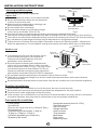
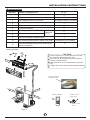
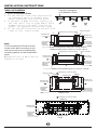
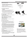
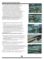
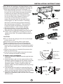
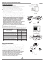
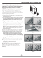
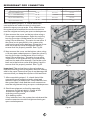
Before using your air conditioner, please read
this manual carefully and keep it for future reference.
INVERTER SPLIT TYPE
ROOM AIR CONDITIONER
SERIES
Please read this installation manual completely
before installing the product.
If the power cord is damaged, replacement work
shall be performed by authorised personnel only.
Installation work must be performed in accordance
with the national wiring Standards by authorised
personnel only.
Contact an authorised service technician for
repair, maintenance or installation of this unit.
CONTENTS
SAFETY PRECAUTIONS
Warning .....................................................................................................................................2
Caution ......................................................................................................................................2
INSTALLATION INSTRUCTIONS
Selecting installation place.........................................................................................................3
Accessories ........ .....................................................................................................................4
Indoor unit installation................................................................................................................8
Outdoor unit installation.............................................................................................................9
REFRIGERANT PIPE CONNECTION
Refrigerant pipe connection ......................................................................................................10
ELECTRICAL WORK
Electrical work .................. .......................................................................................................12
TEST RUNNING
Test running ...................... .....................................................................................................14
CAUTION
Contact an authorised service technician for repair or maintenance of this unit.
Contact the authinstaller for installation of this unit.
This appliance is not intended for use by persons(including children) with reduced
physical, sensory or mental capabilities, or lack of experience and knowledge, unless
they have been given supervision or instruction concerning use of the appliance by a
person responsible for their safety.
Young children should be supervised to ensure that they do not play with the
air conditioner.
If the power cord is to be replaced, replacement work shall be performed by
authorised personnel only.
Installation work must be performed in accordance with the national wiring
standards by authorised personnel only.
1
SAFETY PRECAUTIONS
Read the follow SAFETY PRECAUTIONS carefully before installation.
Installation must be performed in accordance with the requirement of NEC and CEC by
authorized personnel only.
Incorrect installation due to ignoring of the instruction will cause harm or damage, and the
seri ousness is classified by the following indications.
WARNING
This symbol indicates the possibility of death or serious injury.
CAUTION
This symbol indicates the possibility of injury or damage to property.
The items to be followed are classified by the symbols:
Symbol will background white denotes item that is PROHIBITED from doing.
WARNING
1) Engage dealer or specialist for installation. If installation done by the user is defective, it will cause water
leakage, electrical shock or fire.
2) Install according to this installation instructions strictly. If installation is defective, it will cause water
leakage, electrical shock or fire.
3) Use the attached accessories parts and specified parts for installation. otherwise, it will cause the set to fall,
water leakage, electrical shock or fire.
4) Install at a strong and firm location which is able to withstand the set ,s weight. If the strength is not enough
or installation is not properly done, the set will drop and cause injury.
5) For electrical work, follow the local national wiring standard, regulation and this installation instructions. An
independent circuit and single outlet must be used. If electrical circuit capacity is not enough or defect found
in electrical work, it will cause electrical shock or fire.
6) Use the specified cable and connect tightly and clamp the cable so that no external force will be acted on
the terminal. If connection or fixing is not perfect, it will cause heat-up or fire at the connection.
7) Wiring routing must be properly arranged so that control board cover is fixed properly. If control board cover
is not fixed perfectly, it will cause heat-up at connection point of terminal, fire or electrical shock.
8) When carrying out piping connection, take care not to let air substances other than the specified
refrigerant go into refrigeration cycle. Otherwise, it will cause lower capacity, abnormal high pressure
in the refrigeration cycle, explosion and injury.
9) Do not modify the length of the power supply cord or use of extension cord, and do not share the
single outlet with other electrical appliances. Otherwise, it will cause fire or electrical shock.
CAUTION
1) This equipment must be earthed and installed with earth leakage current breaker. It may cause electrical
shock if grounding is not perfect.
2) Do not install the unit at place where leakage of flammable gas may occur. In case gas leaks and
accumulates at surrounding of the unit, it may cause fire.
3) Carry out drainage piping as mentioned in installation instructions. If drainage is not perfect, water
may enter the room and damage the furniture.
2
INSTALLATION INSTRUCTIONS
More than 15cm/5.9in
(to the ceiling)
Selecting installation place
Read completely, then follow step by step.
More than
More than
Indoor unit
12cm/4.72in
12cm/4.72in
Do not expose the indoor unit to heat or steam.
Select a place where there are no obstacles
in front or around the unit.
Make sure that condensation drainage can
be conveniently routed away.
More than 2.3m/7.55ft
Do not install near a doorway.
(from the floor)
Ensure that the space on the left and right
Fig.1
of the unit is more than 12cm/4.72in.
Use a stud finder to locate studs to prevent unnecessary damage to the wall.
The indoor unit should be installed on the wall at a height of 2.3m/7.55ft or more from the floor.
The indoor unit should be installed allowing a minimum clearance of 15cm/5.9in from the ceiling.
Any variations in pipe length will/may require adjustment to refrigerant charge.
There should not be any direct sunlight. Otherwise, the sun will fade the plastic cabinet and
affect its appearance. If unavoidable, sunlight prevention should be taken into consideration.
More than30cm/11.81in
Outdoor unit
More than
30cm/11.81in
If an awning is built over the outdoor unit to
prevent direct sunlight or rain exposure,
make sure that heat radiation from the
condenser is not restricted.
More than
Ensure that the clearance around the back
60cm/23.62in
of the unit is more than 30cm/11.81in and left
side is more than 30cm/11.81in. The front of the
More than 200cm/78.74in
unit should have more than 200cm/78.74in of
clearance and the connection side (right side)
Fig.2
should have more than 60cm/23.62in of clearance.
Do not place animals and plants in the path of the air inlet or outlet.
Take the air conditioner weight into account and select a place where noise and vibration
will not be an issue.
Select a place so that the warm air and noise from the air conditioner do not disturb neighbors.
Rooftop installation:
If the outdoor unit is installed on a roof structure, be sure to level the unit.
Ensure the roof structure and anchoring method are adequate for the unit location.
Consult local codes regarding rooftop mounting.
If the outdoor unit is installed on roof structures or external walls, this may result in excessive
noise and vibration, and may also be classed as a non serviceable installation.
Tools needed for installation:
Level gauge
Screwdriver
Electric drill,Hole core drill (φ90mm/3.54in)
Flaring tool set
Specified torque wrenches: 1.8kgf.m,
4.2kgf.m, 5.5kgf.m, 6.6kgf.m
(different depending on model No.)
Spanner (half union)
3
Hexagonal wrench (4mm/0.157in)
Gas-leak detector
Vacuum pump
Gauge manifold
Users manual
Thermometer
Multimeter
Pipe cutter
Measuring tape
INSTALLATION INSTRUCTIONS
Accessories
Q’ty
1
Name of Accessories
Installation Plate
2
Clip Anchor
5-8(depending on models)
3
Self-tapping Screw A ST3.9X25
5-8(depending on models)
4
Seal (For cooling & heating models only)
1
5
Drain Joint (For cooling & heating models only)
1
6
Remote controller
1
7
Self-tapping Screw B ST2.9X10
8
Remote controller holder
9
Quick connecting refrigerant pipe
Number
1
2
Optional
parts
1
1
10
Air freshening filter(used to install on Air filter)
11
Sound deadening pads(used to wrap up the
quick connectors)
1(depending on models)
2
Note: Except the above parts provided, the other parts needed during installation you
must purchase.
3
2
>15cm/5.9
in
>12
cm
CAUTION
1
Use a stud finder to locate studs to prevent
unnecessary damage to the wall.
Two of the A, B and C directions should be
free from obstructions.
This illustration is for explanation purposes
only.
Copper lines must be insulated independently.
/4.7
2in
>12cm/4.72in
ilter
A
Air Outlet
30c
m
abo
ve
60cm above
>2.3m/7.54ft
Air F
B
abo
e
bov
ma
30c
60c
ve
cm
200
Quick connecting
refrigerant pipe
Remote Controller
ma
bov
Mounting screw B
ST2.9x10-C-H
e
C
6
8
ON/OFF
SHORT
CUT
MODE
7
TIMER ON
TEMP
FAN
TIMER OFF
SLEEP
SWING DIRECT
TURBO
LED
Remote controller
holder
Fig.3
4
INSTALLATION INSTRUCTIONS
Correct orientation
of Installation Plate
Indoor unit installation
1. Fit the Installation Plate
1. F i t t h e i n s t a l l a t i o n p l ate horizontally
o n s t r u c t u r a l p a r t s o f the wall with
s p a c e s a r o u n d t h e i n s t allation plate.
2. I f t h e w a l l i s m a d e o f b rick, concrete or
t h e l i k e , d r i l l f i v e o r eight 5mm/0.197in
d i a m e t e r h o l e s i n t h e wall. Insert Clip
a n c h o r f o r a p p r o p r i a t e mounting screws.
3. F i t t h e i n s t a l l a t i o n p l ate on the wall with
e i g h t o r f i v e t y p e A s crews.
Fig.4
150mm/5.91in or more to ceiling
C
120mm/4.72in
or more to wall
55/ 2.1 7
B
41
55/ 2.1 7
120mm/4.72in
or more to wall
Left rear side
refrigerant
pipe hole
φ90/3.54in
Note:
Fit the Installation Plate and drill
holes in the wall according to the
wall structure and corresponding
mounting points on the installation
plate.
Indoor unit outline
D
Right rear side
refrigerant pipe
hole φ90/3.54in
A
9000Btu/h models(A:680/26.77, B:255/10.04, C:170/6.69, D:92/3.62)
12000Btu/h models(A:770/30.31, B:255/10.04, C:170/6.69, D:95/3.74)
150mm/5.91in or more to ceiling
36.5
55/ 2.1 7
Left rear side
refrigerant
pipe hole
φ90/3.54in
B
120mm/4.72in
or more to wall
120mm/4.72in
or more to wall
55/ 2.1 7
(Dim e n s i o n s a r e i n m m / i n u nless
othe r w i s e s t a t e d )
Indoor unit outline
D
C
A
Right rear side
refrigerant pipe
hole φ90/3.54
18000Btu/h models(A:905/35.63, B:275/10.83, C:80/3.15, D:100/3.94)
150mm/5.91in or more to ceiling
293/11.54
Installation plate
163/6.42
120mm/4.72in
or more to wall
21.5/0.85
55
Left rear side
refrigerant
pipe hole
φ90/3.54in
315/12.4
Indoor unit outline
1030/40.55
120mm/4.72in
or more to wall
Right rear side
refrigerant pipe
hole φ90/3.54
22000Btu/h models
150mm/5.91in or more to ceiling
120mm/4.72in
or more to wall
55/2.17
Left rear side
refrigerant
pipe hole
φ90/3.54in
35/1.38
>30000Btu/h models
Fig.5
5
340/13.39
25/0 .98
1450/57.09
INSTALLATION INSTRUCTIONS
Wall
2. Drill a hole in the wall
Outdoor
Indoor
5-7mm
/0.2-0.28in
1. Determine hole positions according to
the diagram detailed in Fig.5. Drill
one (1) hole (φ90mm/3.54in) slanting
slightly to outdoor side.
2. Always use wall hole conduit when
drilling metal grid, metal plate or the like.
Fig.6
3. Drainage Installation
Drainage
1. Run the drain hose sloping downward. Do not
install the drain hose as illustrated in Fig.7.
2. When connecting extension drain hose, insulate
the connecting part of extension drain hose with
a shield pipe, do not let the drain hose slack.
4. Connecting the refrigerant pipes
4.1 Tools needed
-You will require the following tools to carry out this
installation work correctly:
1x open-ended spanner, 19 mm/0.75in
1x open-ended spanner, 22 mm/0.87in
1x open-ended spanner, 24 mm/0.95in
1x Allen key, 5 mm/0.2in
1x Philips screwdriver
1x leak detection spray or alternatively soap suds
(water/detergent mix)
4.2 Important information
Follow the detailed instructions for connecting
the refrigerant pipes to the indoor unit and
outdoor unit. We can only provide a warranty if
the lines are installed correctly as described in
the instructions.
Do not remove the sealing caps and stoppers
until immediately before you install the lines.
To prevent leaks, ensure that the quick-release
screw connections are absolutely free of dirt.
Moisture or foreign bodies will adversely affect
the function of the quick-release connectors,
leading to a risk of refrigerant loss (not covered
by the warranty).
Only install refrigerant lines outdoors in dry
weather.
The refrigerant lines must not be installed and
then plastered over.
Please make sure that refrigerant is never
allowed to enter the environment.
Improper handling of refrigerant may be harmful
to health. Always wear work gloves and goggles
when handling refrigerant.
6
Do not put the hose
end into water or any
container
Do not form a rise
Fig.7
Refrigerant pipe
Connectors(both ends):
Fig.8
NOTE: To distinguish the connectors
to be connected to the indoor unit and
outdoor unit, the connectors of the
refrigerant pipe has been labelled “A”,
“B”,“C”and “D”. Ensure the
marks on the connectors are the same
to the indoor s and outdoor s respectively
during connection.
,
,
INSTALLATION INSTRUCTIONS
Do not smoke during the installation work.
The equipment must never be operated without
the refrigerant lines connected, otherwise the
equipment will be damaged immediately.
The screw connections may only be tightened
using the appropriate open-ended spanner.
Remember that if they are tightened with too
little torque they will leak but if they are tightened
with too much torque, the screw connections may
suffer damage. If you should not be confident
about connecting the refrigerant line connectors
yourself, it is imperative that you contact your
customer service team or a refrigeration contractor.
Important! The EQ valves are only designed for
one-time installation. Their seal can not be
guaranteed if they are installed on more than one
occasion. This will also void the warranty.
4.3 Connecting the refrigerant pipes to indoor
unit
1. Do not remove the plastic seals from the indoor
equiopment and the appropriate refrigerant pipe
until immediately before you connect them.
2. Align the refrigerant pipes correctly, make sure
the dimensions of the connecting refrigerant pipe
are the same. Place the screw connector on the
refrigerant pipes just on to the thread on the
indoor equipment and tighten the first few threads
by hand. See Fig.9.
IMPORTANT: Before you continue, it is essential
that you read the following instructions carefully.
Fig.9
A
B
Fig.10a
Fig.10b
,, ,,
3. Hold the points marked A using a 22mm/0.87in openended spanner
and turn the nuts only at the points
,, ,,
marked B using a 24mm/0.95in open-ended spanner.
See Fig.10a & 10b.
4. Ensure that the screw connectors do not skew as
you tighten them and work quickly.
IMPORTANT: Since the coupling works with tapping
rings, it may leak if you undo and reconnect the
pipes. This will also void the warranty.
Fig.11
5. After finishing the connection, first wrap up the quick
connectors with the sound deadening pads(packed with
accessories) solidly and tightly as shown in Fig.11,
then use the tape to wrap the refrigerant pipe and
connecting cable together. See Fig.12.
NOTE: For aesthetic reason, the quick connector parts
are recommended to be placed outside of room.
Fig.12
7
INSTALLATION INSTRUCTIONS
Note: Route the package of pipes/hoses in the
direction of (rear)right or (rear)left. See Fig.13 .
1.Both sides drainage structure is standard. For
both sides drainage structure, it can be choosen
for right, left or both sides drainage connection.
If choosing both sides drainage connection,
another proper drain hose is needed as there
is only one drain hose offered by factory. If
choosing one side drainage connection,
make sure the drain hole on the other side is
well plugged. For 9k/12k models, if choosing
left-hand or left-back piping,please choosing
left side drainage connection. The connection
of the drain hose is supposed to be done by
qualified installer in case of water leakage.
2. Bundle the tubing, connecting cable with
tape securely, evenly as shown in Fig.14.
Because the condensed water from rear of the
indoor unit is gathered in ponding box and is
piped out of room. Do not put anything else in
the box.
Rubber plug
CAUTION:
Do not allow the piping to let out from the back
of the indoor unit.
Be careful not to let the drain hose slack.
Heat insulated both of the auxiliary piping.
Be sure that the drain hose is located at the
lowest side of the bundle. Locating at the upper
side can cause drain pan to overflow inside the
unit.
Never intercross nor intertwist the power wire
with any other wiring.
Run the drain hose sloped downward to drain
out the condensed water smoothly.
5. Indoor unit installation
1. Feed the package of pipes/hoses through the hole
in the wall.
2. Hook the indoor unit onto the upper portion of the
installation plate.(Engage the two hooks of the rear
top of the indoor unit with the upper edge of the
installation plate.) Ensure that the hooks are
properly seated on the installation plate by moving
it left and right.
3. The female half can easily be made by lifting the
indoor unit with a cushioning material between the
indoor unit and the wall. Get it out after finish piping.
4. Press the lower left and right sides of the unit
against the installation plate until the hooks engage
into their slots.
8
Fig.13
Indoor unit
Ponding box
Connective
cable
Pipe room
......
. ..
......
..
..
.
........
.
. .
Drain hose
Fig.14
Fig.15
Connective
pipe
Wrapping belt
INSTALLATION INSTRUCTIONS
Outdoor unit installation
Outdoor unit
1. Outdoor installation precaution
Select the location for installation(follow the previous
notes on selecting the installation place).
If the outdoor unit is higher thanthe indoor unit,
make sure that a curve is made in the refrigerant
pipe which is lower than the bottom edge of the
indoor unit. See Fig.16.
In the case that the installation place is exposed to
strong wind such as a seaside, make sure the fan
operating properly by putting the unit lengthwise
along the wall or using a dust or shield plates, Fig.17.
If need suspending installation, the installation
bracket should accord with technique requirement
in the installation bracket diagram. The installation
wall should be solid brick, concrete or the same
intensity construction, or actions to reinforce,
damping supporting should be taken. The connection
between bracket and wall, bracket and the air
conditioner should be firm, stable and reliable.
Be sure there is no obstacle which block radiating air.
Refrigerant pipe
Indoor unit
Curve
Fig.16
Strong
wind
Fig.17
2. Settlement of outdoor unit
Anchor the outdoor unit with a bolt and nutφ10 or φ8
tightly and horizontally on a concrete or rigid mount.
Outdoor unit dimension
mm/in(WxHxD)
Mounting dimensions
A(mm/in)
B(mm/in)
760(29.92)x590(23.23)x285(11.22)
530(20.87)
290(11.42)
A
820(32.28)x595(23.43)x330(12.99)
523(20.59)
340(13.39)
Air inlet
780(30.71)x540(21.26)x250(9.84)
549(21.61)
276(10.87)
660(25.98)x242(9.52)x540(21.26)
458(18.03)
276(10.87)
840(33.07)x700(27.56)x320(12.6)
560(22.05)
335(13.19)
990(38.98)x965(37.99)x345(13.58)
624(24.57)
366(14.41)
W
D
B
Air inlet
Air outlet
Fig.18
Drain joint installation
NOTE: The drain joint is slightly different according
to the different outdoor unit.
For the drain joint with the seal(Fig.19 (A)), first fit the
seal onto the drain joint, then insert the drain joint
。
into the base pan hole of outdoor unit, rotate 90 to
securely assemble them. To install drain joint as
shown in Fig.19 (B), insert the drain joint
into the base pan hole of outdoor unit until it remains
fixed with a clicking sound. Connecting the drain
joint with an extension drain hose (Locally
purchased), in case of the water draining off the
outdoor unit during the heating mode.
9
Seal
Drain joint
Base pan hole of
outdoor unit
(B)
Seal
Drain pipe
(A)
Fig.19
REFRIGERANT PIPE CONNECTION
4. Connecting the refrigerant pipe to outdoor unit
CAUTION: For your safety, always wear goggles
and work gloves when connecting the pipes.
NOTE: To distinguish the connectors to be connected
to the indoor unit and outdoor unit, the connectors
of the refrigerant pipe has been labelled “A”,
“B”,“C”and “D”. Ensure the marks
on the ,
,
connector are the same to the indoor s and outdoor s
respectively during connection.
1. First remove the water tray on the outdoor unit
as shown in Fig.20.
2. Do not remove the plastic seals from the outdoor
unit and the appropriate refrigerant pipes until
immediately before you connect them, Fig.21.
3. Align the refrigerant pipes correctly so that they
line up with the valves and are not stressed.
Place the screw connector on the refrigerant line
just on to the thread on the outdoor unit and
tighten the first few threads by hand, Fig.22.
NOTE: The refrigerant pipes must be connected
to the valves on the outdoor unit with as little
stress as possible.
IMPORTANT: Before you continue, it is essential
that you read the following instructions carefully.
4. Now tighten the bottom screw connector first
and then the top screw connector using the
open-ended spanner. Hold the points marked
“A”using a 22mm/0.87in open-ended spanner
and turn the nuts only at the points marked “B”
using a 24mm/0.95in open-ended spanner, see
Fig.23.
Ensure that the screw connectors do not skew
as you tighten them and work quickly. See the
next page for the proper torque.
Fig.20
Fig.21
Fig.22
IMPORTANT: Since the coupling works with
tapping rings, it may leak if you undo and
reconnect the pipes. This will also void the
warranty.
A B
B
A
Fig.23
10
REFRIGERANT PIPE CONNECTION
Coupling size (last 2 part numbers)
Pound-force foot(1bf-ft)
Newton meter(N-m)
Kilogram-force meter(kgf-m)
-06(9.5mm/3/8 dash size)
18 - 20
24.4 - 27.1
2.4 - 2.7
-08(12.7mm/1/2 dash size)
30 - 35
40.6 - 47.4
4.1 - 4.8
-12(19.1mm/3/8 dash size)
45 - 50
61.0 - 67.7
6.2 - 6.9
-16(25.4mm/1 dash size)
60 - 65
81.3 - 88.1
8.2 - 8.9
After completing steps 1- 4, check that all the
connections are sealed correctly using leak
detection spray or soap suds. If any bubbles form,
the system has a leak and the screw connectors
must be retightened using an open-ended spanner.
5. Now remove the cover on the top valve using a
19 mm open-ended spanner. Open the valve by
turning it counter-clockwise as far as it will go
using a 5 mm Allen key. The valve is now open. If
the valve is not opened fully, the system may
malfunction and suffer damage. Screw the cover
back on to the top valve and tighten it well to
ensure that it is properly sealed. See Fig.24.
6. Now remove the cover on the bottom valve using
a 19 mm open-ended spanner. Open the valve by
turning it counter-clockwise as far as it will go
using a 5 mm Allen key. The valve is now open.
If the valve is not opened fully, the system may
malfunction and suffer damage. Screw the cover
back on to the bottom valve and tighten it well to
ensure that it is properly sealed. See Fig.25.
Fig.24
Important! The conical ring on the valve has an
important sealing function together with the sealing
seat in the caps. Ensure that you do not damage the
cone and that you keep the cap free of dirt and dust.
7. After completing steps 1- 6, check that all the
connections are sealed correctly using leak
detection spray or soap suds. If any bubbles form,
the system has a leak and the screw connectors
must be retightened using an open- ended spanner.
8. Start the equipment so that the operating
pressures build up inside it. Check all the
connectors again for signs of leaks
a) during cooling mode
b) in heating mode.
If any bubbles form, the system has a leak and the
screw connectors must be retightened using an
open-ended spanner.
Fig.25
11
ELECTRICAL WORK
CAUTION
CAUTION
CAUTION
CAUTION
After the confirmation of the above conditions, prepare the wiring as follows:
1) Never fail to have an individual power circuit specifically for the air conditioner. As for
the method of wiring, be guided by the circuit diagram posted on the inside of control
cover.
2) The screw which fasten the wiring in the casing of electrical fittings are liable to come
loose from vibrations to which the unit is subjected during the course of
transportation. Check them and make sure that they are all tightly fastened. (If they
are loose, it could cause burn-out of the wires.)
3) Specification of power source.
4) Confirm that electrical capacity is sufficient.
5) See to that the starting voltage is maintained at more than 90 percent of the rated
voltage marked on the name plate.
6) Confirm that the cable thickness is as specified in the power source specification.
7) Always install an earth leakage circuit breaker in a wet or moist area.
8) The following would be caused by voltage drop.
Vibration of a magnetic switch, which will damage the contact point, fuse breaking, disturbance of the
normal function of the overload.
Electrical work
Electric safety regulations for the initial Installation
1. If there is serious safety problem about the power supply, the technicians should refuse to install
the air conditioner and explain to the client until the problem is solved.
2. Power voltage should be in the range of 90%~110%of rated voltage.
3. The surge protector and main power switch with a 1.5 times capacity of Max. Current of the unit
should be installed in power circuit. Ensure the air conditioner is grounded well.
4. The appliance shall be installed in accordance with national wiring regulations. Do not operate your
air conditioner in a wet room such as a bathroom or laundry room.
5. An all-pole disconnection device which has at least 3mm clearances in all poles, and have a leakage
current that may exceed 10mA, the residual current device(RCD) having a rated residual operating
current not exceeding 30mA, and disconnection must be incorporated in the fixed wiring in
accordance with the wiring rules.
6. For the unit adopts auxiliary electric heater, keep at least 1 meter away from the nearest combustible
materials.
7. According to the attached Electrical Connection Diagram located on the panel of the indoor & outdoor
unit to connect the wire. All wiring must comply with local and national electrical codes and be
installed by qualified and skilled electricians.
8. An individual branch circuit and single receptacle used only for this air conditioner must be available.
See the following table for suggested wire sizes and fuse specifications:
Suggest Minimum Wire Size (AWG:American Wire Gage):
Appliance Amps
NOTE:
AWG Wire Size
10
18
13
16
18
14
25
12
30
10
40
8
The wire size of power supply cord and
interconnected wire and the current of the fuse
or switch are determined by the maximum
current indicated on the nameplate which
located on the side panel of the unit. Please
refer to the nameplate before selecting the
wire size, fuse or switch.
The controller of the air conditioner designed
with a fuse protection function under abnormal
conditions, the specifications of the fuse have
printed on the circuit board, such as:
T3.15A/250VAC, T5A/250VAC, etc.
12
ELECTRICAL WORK
Front Panel
Connect the cable between indoor
unit and outdoor unit
Electronic box
cover
NOTE: Before performing any electrical
work, turn off the main power to the system.
1. The connection cables of indoor and outdoor
units have been connected to the terminals
on the control board except the grounding
wire(Y/G), only white plug connectors exposed.
See Fig.27.
2. Remove the control cover from the outdoor
unit by loosening the screw.
3. Hold the indoor male plug and insert it into the
female plug of the outdoor unit until it fixed with
a clicking sound. Secure the cable onto the
control board with the cord clamp. See Fig.27.
4. Connect the grounding wire to the terminal on the
control board individually.
5. The electrical connection has finished now.
Fig.26
Terminal block of indoor unit
L
N
L
N
S
or
S
L1 L2
L2
L1
S
S
Cord clamp
G
G
Cover
To outdoor unit
Screw
To outdoor unit
208-230V~60Hz
115V~60Hz
Terminal block of outdoor unit
1(L) 2(N) S
L
L1 L2
N
G
G
To power supply
S
L1 L2
G
G
To power supply
To indoor unit
To indoor unit
208-230V~60Hz
115V~60Hz
Fig.27
13
TEST RUNNING
Test running
Perform test operation after completing gas leak check at the flare nut connections and
electrical safety check.
Check that all tubing and wiring have been properly connected.
Check that the gas and liquid side service valves are fully open.
1. Connect the power, press the ON/OFF button on the remote controller to turn the unit on.
2. Use the MODE button to select COOL, HEAT, AUTO and FAN to check if all the functions
works well.
3. When the amient temperature is too low(lower than 17 C/62 O F), the unit cannot be
controlled by the remote controller to run at cooling mode, manual operation can be taken.
Manual operation is used only when the remote controller is disable or maintenance
necessary.
Hold the panel sides and lift the panel up to an angle until it remains fixed
with a clicking sound.
Press the Manual control button to select the AUTO or COOL, the unit will
operate under Forced AUTO or COOL mode(see User Manual for details).
4. The test operation should last about 30 minutes.
Manual control
button
AUTO/COOL
Fig.28
14
The Klimaire logo is a registered Trademark of Klimaire Products inc.
Copyright 2010 Klimaire Products Inc.
2190 NW 89 Place, Doral, FL 33172 - USA
Tel: (305)593-8358 Fax (305) 675-2212
www.klimaire.com
[email protected]
The design and specifications are subject to change without prior notice for product
improvement. Consult with the sales agency or manufacturer for details.