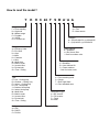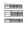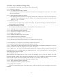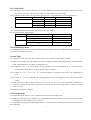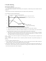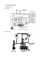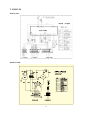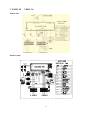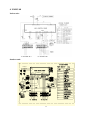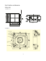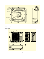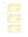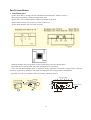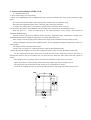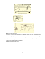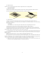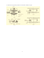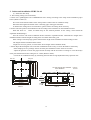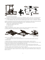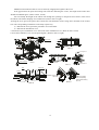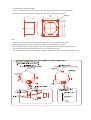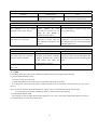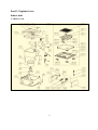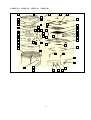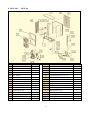
1
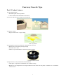
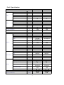
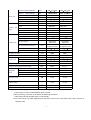
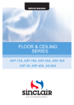
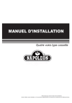
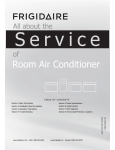
Cassette
YKHC 18 to 48
SERVICE MANUAL
YKHC 18 · YKHC 24 · YKHC 30 · YKHC 36 · YKHC 48
SM-YKHC-18-48GB 03-07
How to read the model?
Y K H C 24 F S B* A* * A A
Range:
F = Floor standing
H = High wall
M = Master range
P = Portable
Y = YORK
R = Everest front
Generation:
A = First
R = New remote
Voltages:
A = (Out) 220-240/1/50 - (In) 220-240/1/50
C = (Out) 380/3/50 - (In) 220-240/1/50
Family:
A = Efficiency Ultra
E = Eco Ultra
H = Alps
J = Atlas
K = Cassette
L = Ultra
M = Multi Ultra
R = Multi Inverter
V = Inverter Ultra
U = Ducted unit
O = Floor / Ceiling
Type:
C = Set - Cooling only
D = Outdoor - Cooling only
E = Indoor - Cooling only
H = Set - Heat pump
J = Outdoor Heat pump
K = Indoor Heat pump
M = Multi Ultra
R = Multi Inverter
V = Inverter Ultra
U = Ducted unit
O = Floor / Ceiling
Refrigerant type:
A = R22
B = R407C
C = R410A
Indoor options:
A = Standard
J = Bio Screen filter
** Omit for outdoor units
Outdoor options:
A = Standard
B = Low Ambient Kit
C = Power outdoor
* Omit for indoor units
Indoors:
A = Free matching multi
S = Single
T = Duct High Static
U = Duct standard case
Compressor type:
A = AC Inverter
D = DC Inverter
F = Fixed
M = Multi
Capacity Btu/h
Four-way Cassette Type
Part1. Product features
1) Low operation noise
---Streamline plate ensures quietness
---Creates natural and comfortable environment
2) Fresh air make life more healthy and comfortable.
3) Efficient cooling
---Equal, fast and wide—range cooling
Four-way airflow
4) The adoption of the most advanced 3- Dimensional Screw fan
---Reduces the air resistance passing through
---Smoothes the air flow
---Makes air speed distribution to the heat exchange uniform
3- Dimensional Screw fan
5) Improvement for easy installation and maintenance
---Little space is required for installation into a shallow ceiling
---Because of the compactness and weight reduction of the main unit and panel, all models can be installed
without a hoist
1
Part2. Specification
Model
P o w er s u pply
P h - V- H z
Capacity
Btu/h
Capacity
kW
YKHC-18
YKHC-24
1,220-240V,50Hz
1,220-240V,50Hz
18000
24000
5.3
7.1
In p u t
W
1900
2560
R a te d c u r r e n t
A
8.8
12.2
B tu /W. h
9.6
9.6
B tu /h
20500
27300
6.0
8.0
In p u t
W
1900
2500
R a te d c u r r e n t
A
8.8
11
B tu /W. h
10.7
10.9
M o i s tu r e R e m o v a l
L /h
1.8
2.4
M a x . i n p u t c o n s u m p ti o n
W
2300
3300
Ma x . c u r r e n t
A
11.7
15.3
S ta r ti n g c u r r e n t
A
45
60
PA290X3CS-4MU1
C-SBN303H8D
Cooling
EER
C a p a c i ty
Capacity
Heating
C OP
kW
Model
Type
ROTARY
SCROLL
Brand
TOSHIBA
SANYO
TOSHIBA
(Guangdong)
18362
Supplier
C a p a c i ty
Compressor
B tu /h
W
1855
2440
R a te d c u r r e n t( R L A )
A
8.6
11.4
80
85
INNER
INNER
50
50
A
Thermal protector
C a p a c i to r
uF
R efrig era n t o il
ml
750
950
Model
YDK45-4F
YDK55-6
Brand
WELING
WELING
63
120
In p u t
W
C a p a c i to r
uF
2.5
3.5
r /m i n
930/830
680/600
S p e e d ( h i /l o )
Number of rows
Tubepitch(a)x row pitch(b)
mm
21 13.37
21 13.37
1.3
Hydrophilic
aluminium
Ø7, innergroove
tube
1950 126 26.74
m /h
3
860/760
1050/900
dB (A )
43/40
43/40
Tube outside dia.and type
mm
Coil length x height x width
mm
I n d o o r n o i s e l e v e l ( H i /L o )
2
1.3
mm
Fin type (code)
I n d o o r a i r f l o w ( H i /L o )
2
Hydrophilic
aluminium
Ø7, innergroove
tube
1185 210 26.7
F in s pa c in g
Indoor coil
24574
In p u t
Locked rotor Amp(LRA)
Indoor fan motor
SANYO(Dalian)
2
Dimension (W*H*D)(body)
mm
580 254 580
840 240 840
Packing
mm
750 340 750
1020 330 930
kg
21/30
36/46
(W*H*D)(body)
Net/Gross weight(body)
Indoor unit
Dimension (W*H*D)(panel)
mm
650 30 650
950 40 950
Packing
mm
715 115 715
1030 145 1030
kg
3/5
6/11
(W*H*D)(panel)
Net/Gross weight(panel)
Outdoor
motor
fan
Model
YDK53-6K
YDK53-6H
Brand
WELLING
WELLING
Input
Capacitor
Speed
W
130
uF
2.5
3
r/min
750
800
2
2
25.4 22
25.4 22
Number of rows
Outdoor coil
Tube pitch(a)x row pitch(b)
mm
Fin spacing
mm
1.8
Fin type (code)
Tube outside dia.and type
mm
Coil length x height x width
mm
Outdoor noise level
Dimension(W*H*D)
Outdoor unit Packing (W*H*D)
Net/ Gross weight
Refrigerant type/Quantity
1.5
Hydrophilic
aluminium
Ø9.53,
innergroove tube
775 660 44
Hydrophilic
aluminium
Ø9.53,
innergroove tube
850 810 44
3
4
Number of circuits
O u td o o r a i r f l o w
130
3
2400
3000
dB(A)
mm
m /h
48
845 695 335
55
895 860 330
mm
965 847 395
1000 985 410
kg
55/58
79/90
g
R410A/2050
MPa
4.2/2.5
4.2/2.5
Liquid side
mm(inch)
6.35 (1/4)
9.53 (3/8)
Refrigerant
Gas side
mm(inch)
12.7 (1/2)
16 (5/8)
piping
Max. pipe length
m
30
30
Max. difference in level
m
20
20
Operation temp
17~30
17~30
Ambient temp
-7~45
-7~45
m
34~49
40~56
Pieces
56/123/140
30/63/66
Design pressure (high side/low side)
Application area
Qty’per 20’& 40’Fcl
2
R410A/2600
Notes: 1. Nominal cooling capacities are based on the following conditions:
Indoor temp: 27°CDB, 19°CWB; Outdoor temp: 35°CDB;
2. Nominal heating capacities are based on the following conditions:
Indoor temp: 20°CDB; Outdoor temp: 7°CDB, 6°CWB;
3. Actual noise level may differ, depending on the room structure, etc, since these noise values are from an
anechoic room.
3
Model
YKHC-30
YKHC-36
YKHC-48
Ph-V-Hz
3,380V,50Hz
3,380V,50Hz
3,380V,50Hz
Capacity
Btu/h
30000
36000
48000
Capacity
kW
8.8
10.5
14
Input
W
3250
3700
4700
Rated current
A
5.5
6.5
8.2
Btu/W.h
9.3
9.6
9.6
Capacity
Btu/h
32000
39000
52000
Capacity
kW
9.4
11.4
15.2
Input
W
3250
3350
4900
Rated current
A
5.5
5.8
8.6
Btu/W.h
10.9
11.5
10.6
Moisture Removal
L/h
3.0
3.0
4.8
Max. input consumption
W
4620
4620
5870
Max. current
A
8.5
8.5
10.7
Starting current
A
31
31
41
Model
C-SBN303H8D
C-SBN303H8D
C-SBN373H8D
Type
SCROLL
SCROLL
SCROLL
Brand
SANYO
SANYO
SANYO
SANYO(Dalian)
SANYO(Dalian)
SANYO(Dalian)
Btu/h
33500
33500
48123
W
3650
3650
4750
Rated current(RLA)
A
6.58
6.58
8.22
Locked rotor Amp(LRA)
A
65
65
82
INNER
INNER
INNER
Capacitor
uF
/
/
/
Refrigerant oil
Power supply
Cooling
EER
Heating
COP
Supplier
Capacity
Compressor Input
Thermal protector
ml
1700
1700
1700
Model
YDK56-6
YDK56-6
YDK56-6
Brand
WELLING
WELLING
WELLING
Input
W
137
137
137
Capacitor
uF
3
3
3
r/min
670/565
670/565
670/565
2
2
2
Tubepitch(a)x row pitch(b)
mm
2113.37
2113.37
2113.37
Fin spacing
mm
1.3
1.3
1.3
Hydrophilic
aluminium
Tube outside dia.and type
mm
Ø7, innergroove
tube
Coil length x height x width
mm
195016826.74
Hydrophilic
aluminium
Ø7, innergroove
tube
195016826.74
Hydrophilic
aluminium
Ø7, innergroove
tube
195016826.74
Indoor air flow (Hi/Lo)
3
m /h
1600/1420
1600/1420
1600/1420
Indoor noise level (Hi/Lo)
dB(A)
47/44
47/44
47/44
Indoor
motor
fan
Speed(hi/lo)
Number of rows
Indoor coil
Fin type (code)
4
Dimension (W*H*D)(body)
mm
840310840
840310840
840310840
Packing
mm
1020400930
1020400930
1020400930
Net/Gross weight(body)
kg
40/50
40/50
40/50
Dimension (W*H*D)(panel)
mm
95040950
95040950
95040950
Packing
mm
10301451030
10301451030
10301451030
kg
6/11
6/11
6/11
Model
YDK250-6D-WL
YDK250-6D-WL
Outdoor fan Brand
motor
Input
WELLING
WEILING
YDK65-6WL;
YDK65-6F
WELLING
W
307
307
138+156
uF
10
10
3.52
r/min
740
740
800
Indoor unit
(W*H*D)(body)
(W*H*D)(panel)
Net/Gross weight(panel)
Capacitor
Speed
Number of rows
2
2
2
Tube pitch(a)x row pitch(b)
mm
25.422
25.422
25.422
Fin spacing
mm
1.7
1.7
1.8
unhydrophilic
aluminium
Tube outside dia.and type
mm
Ø9.53,
innergroove tube
Coil length x height x width
mm
95591544
unhydrophilic
aluminium
Ø9.53,
innergroove tube
95591544
hydrophilic
aluminium
Ø9.53,
innergroove tube
715122044
8
8
4
Outdoor air flow
3
m /h
8
5000
5000
Outdoor noise level
dB(A)
5000
57
58
mm
990960360
9401245360
mm
57
990960360
11201090435
10201370435
kg
11201090435
101/106
110/125
g
R410A/3100
R410A/3100
R410A/4000
Design pressure (high side/low side)
Liquid side
MPa
mm(inch)
4.2/2.5
12.7 (1/2)
4.2/2.5
12.7 (1/2)
4.2/2.5
12.7 (1/2)
Refrigerant
Gas side
mm(inch)
19 (3/4)
19 (3/4)
19 (3/4)
piping
Max. pipe length
m
30
30
30
Max. difference in level
m
20
20
20
17~30
17~30
17~30
-7~45
-7~45
-7~45
m
50~75
60~85
80~105
Pieces
25/55/62
25/55/62
24/52/55
Outdoor coil
Fin type (code)
Number of circuits
Dimension(W*H*D)
Outdoor unit Packing (W*H*D)
Net/ Gross weight
Refrigerant type/Quantity
Operation temp
Ambient temp
Application area
Qty’per 20’& 40’Fcl
2
Notes: 1. Nominal cooling capacities are based on the following conditions:
Indoor temp: 27°CDB, 19°CWB; Outdoor temp: 35°CDB;
2. Nominal heating capacities are based on the following conditions:
Indoor temp: 20°CDB; Outdoor temp: 7°CDB, 6°CWB;
3. Actual noise level may differ, depending on the room structure, etc, since these noise values are from an
5
anechoic room.
Part 3. Noise level
FOUR-WAY CASSETTE TYPE
1.0m
Microphone
30,000~48,000 btu/h
Sound pressure level dB £¨0dB=0.0002 |Ì bar £©
Sound pressure level dB £¨0dB=0.0002 |Ì bar £©
12.000~24,000 btu/h
Audibility limits of
continuous white
sound
Audibility limits of
continuous white
sound
Octave band center frequency£¨Hz£©
Octave band center frequency£¨Hz£©
6
Part4. Velocity & temperature distribution
Discharge angle 60º
Airflow velocity
Temperature
Part5. Operation range
Ensure the operating temperature is in allowable range.
Heating
Cooling
Ambient emp.(¡ã C)
17
Ambient emp.(¡ã C)
52
45
STD
35
STD
6
17
-7
-7
17
24
17
30
24
30
Indoor temp.(¡ã C)
Indoor temp.(¡ã C)
7
Part6. Capacity table
Model: YKHC 12-18
COOLING
Indoor
Conditions
21ºC D
15ºC W
24ºC D
17ºC W
27ºC D
19ºC W
32ºC D
23ºC W
OUTDOOR CONDITIONS
21ºC
25ºC
30ºC
35ºC
40ºC
45ºC
50ºC
Total capacity kW
5.12
4.90
4.72
4.45
4.27
4.14
4.01
Sensitive capacity kW
4.10
3.92
3.78
3.56
3.42
3.31
3.21
Input kW.
1.20
1.37
1.54
1.71
1.88
2.05
2.22
Total capacity kW
5.61
5.36
5.17
4.88
4.68
4.53
4.39
Sensitive capacity kW
4.49
4.29
4.13
3.90
3.74
3.63
3.51
Input kW.
1.26
1.44
1.62
1.81
1.99
2.17
2.35
Total capacity kW
6.10
5.83
5.62
5.30
5.09
4.93
4.77
Sensitive capacity kW
4.88
4.66
4.49
4.24
4.07
3.94
3.82
Input kW.
1.33
1.52
1.71
1.90
2.09
2.28
2.47
Total capacity kW
7.01
6.70
6.46
6.10
5.85
5.67
5.49
Sensitive capacity kW
Input kW.
5.61
5.36
5.17
4.88
4.68
4.53
4.39
1.53
1.75
1.97
2.19
2.40
2.62
2.84
Model: YKHC 12-18
HEATING
OUTDOOR CONDITIONS
Indoor
Conditions
15ºC
18ºC
20ºC
22ºC
27ºC
Capacity kW
Input kW.
Capacity kW
Input kW.
Capacity kW
Input kW.
Capacity kW
Input kW.
Capacity kW
Input kW.
24ºC D
12ºC D
7ºC D
4ºC D
0ºC D
-5ºC D
-7ºC D
-15ºC D
18ºC W
11ºC W
6ºC W
3ºC W
-1ºC W
-6ºC W
-8ºC W
-16ºC W
7.20
5.76
4.80
4.32
4.08
3.60
3.36
3.12
2.28
1.82
1.52
1.44
1.37
1.29
1.22
1.06
8.10
6.48
5.40
4.86
4.59
4.05
3.78
3.51
2.57
2.05
1.71
1.62
1.54
1.45
1.37
1.20
9.00
7.20
6.00
5.40
5.10
4.50
4.20
3.90
2.85
2.28
1.90
1.81
1.71
1.62
1.52
1.33
9.90
7.92
6.60
5.94
5.61
4.95
4.62
4.29
3.14
2.51
2.09
1.99
1.88
1.78
1.67
1.46
11.70
9.36
7.80
7.02
6.63
5.85
5.46
5.07
3.71
2.96
2.47
2.35
2.22
2.10
1.98
1.73
8
Model: YKHC-24
COOLING
Indoor
Conditions
21ºC D
15ºC W
24ºC D
17ºC W
27ºC D
19ºC W
32ºC D
23ºC W
OUTDOOR CONDITIONS
21ºC
25ºC
30ºC
35ºC
40ºC
45ºC
50ºC
Total capacity kW
6.86
6.56
6.32
5.96
5.73
5.55
5.37
Sensitive capacity kW
5.49
5.25
5.06
4.77
4.58
4.44
4.29
Input kW.
1.61
1.84
2.07
2.30
2.53
2.76
3.00
Total capacity kW
7.51
7.19
6.92
6.53
6.27
6.07
5.88
Sensitive capacity kW
6.01
5.75
5.54
5.23
5.02
4.86
4.70
Input kW.
1.70
1.95
2.19
2.43
2.68
2.92
3.16
Total capacity kW
8.17
7.81
7.53
7.10
6.82
6.60
6.39
Sensitive capacity kW
6.53
6.25
6.02
5.68
5.45
5.28
5.11
Input kW.
1.79
2.05
2.30
2.56
2.82
3.07
3.33
Total capacity kW
9.39
8.98
8.65
8.17
7.84
7.59
7.35
Sensitive capacity kW
Input kW.
7.51
7.19
6.92
6.53
6.27
6.07
5.88
2.06
2.36
2.65
2.94
3.24
3.53
3.83
Model: YKHC-24
HEATING
OUTDOOR CONDITIONS
Indoor
Conditions
15ºC
18ºC
20ºC
22ºC
27ºC
Capacity kW
Input kW.
Capacity kW
Input kW.
Capacity kW
Input kW.
Capacity kW
Input kW.
Capacity kW
Input kW.
24ºC D
12ºC D
7ºC D
4ºC D
0ºC D
-5ºC D
-7ºC D
-15ºC D
18ºC W
11ºC W
6ºC W
3ºC W
-1ºC W
-6ºC W
-8ºC W
-16ºC W
9.60
7.68
6.40
5.76
5.44
4.80
4.48
4.16
3.00
2.40
2.00
1.90
1.80
1.70
1.60
1.40
10.80
8.64
7.20
6.48
6.12
5.40
5.04
4.68
3.38
2.70
2.25
2.14
2.03
1.91
1.80
1.58
12.00
9.60
8.00
7.20
6.80
6.00
5.60
5.20
3.75
3.00
2.50
2.38
2.25
2.13
2.00
1.75
13.20
10.56
8.80
7.92
7.48
6.60
6.16
5.72
4.13
3.30
2.75
2.61
2.48
2.34
2.20
1.93
15.60
12.48
10.40
9.36
8.84
7.80
7.28
6.76
4.88
3.90
3.25
3.09
2.93
2.76
2.60
2.28
9
Model: YKHC-30
COOLING
Indoor
Conditions
21ºC D
15ºC W
24ºC D
17ºC W
27ºC D
19ºC W
32ºC D
23ºC W
OUTDOOR CONDITIONS
21ºC
25ºC
30ºC
35ºC
40ºC
45ºC
50ºC
Total capacity kW
8.50
8.13
7.84
7.39
7.10
6.87
6.65
Sensitive capacity kW
6.80
6.50
6.27
5.91
5.68
5.50
5.32
Input kW.
2.05
2.34
2.63
2.93
3.22
3.51
3.80
Total capacity kW
9.31
8.91
8.58
8.10
7.77
7.53
7.29
Sensitive capacity kW
7.45
7.12
6.87
6.48
6.22
6.02
5.83
Input kW.
2.16
2.47
2.78
3.09
3.40
3.71
4.01
Total capacity kW
10.12
9.68
9.33
8.80
8.45
8.18
7.92
Sensitive capacity kW
8.10
7.74
7.46
7.04
6.76
6.55
6.34
Input kW.
2.28
2.60
2.93
3.25
3.58
3.90
4.23
Total capacity kW
11.64
11.13
10.73
10.12
9.72
9.41
9.11
Sensitive capacity kW
Input kW.
9.31
8.91
8.58
8.10
7.77
7.53
7.29
2.62
2.99
3.36
3.74
4.11
4.49
4.86
Model: YKHC-30
HEATING
Indoor
Conditions
15ºC
18ºC
20ºC
22ºC
27ºC
Capacity kW
Input kW.
Capacity kW
Input kW.
Capacity kW
Input kW.
Capacity kW
Input kW.
Capacity kW
Input kW.
OUTDOOR CONDITIONS
24ºC D
12ºC D
7ºC D
4ºC D
0ºC D
-5ºC D
-7ºC D
-15ºC D
18ºC W
11ºC W
6ºC W
3ºC W
-1ºC W
-6ºC W
-8ºC W
-16ºC W
11.28
9.02
7.52
6.77
6.39
5.64
5.26
4.89
3.90
3.12
2.60
2.47
2.34
2.21
2.08
1.82
12.69
10.15
8.46
7.61
7.19
6.35
5.92
5.50
4.39
3.51
2.93
2.78
2.63
2.49
2.34
2.05
14.10
11.28
9.40
8.46
7.99
7.05
6.58
6.11
4.88
3.90
3.25
3.09
2.93
2.76
2.60
2.28
15.51
12.41
10.34
9.31
8.79
7.76
7.24
6.72
5.36
4.29
3.58
3.40
3.22
3.04
2.86
2.50
18.33
14.66
12.22
11.00
10.39
9.17
8.55
7.94
6.34
5.07
4.23
4.01
3.80
3.59
3.38
2.96
10
Model: YKHC-36
COOLING
Indoor
Conditions
21ºC D
15ºC W
24ºC D
17ºC W
27ºC D
19ºC W
32ºC D
23ºC W
OUTDOOR CONDITIONS
21ºC
25ºC
30ºC
35ºC
40ºC
45ºC
50ºC
Total capacity kW
10.14
9.70
9.35
8.82
8.47
8.20
7.94
Sensitive capacity kW
8.11
7.76
7.48
7.06
6.77
6.56
6.35
Input kW.
2.33
2.66
3.00
3.33
3.66
4.00
4.33
Total capacity kW
11.11
10.63
10.24
9.66
9.27
8.98
8.69
Sensitive capacity kW
8.89
8.50
8.19
7.73
7.42
7.19
6.96
Input kW.
2.46
2.81
3.16
3.52
3.87
4.22
4.57
Total capacity kW
12.08
11.55
11.13
10.50
10.08
9.77
9.45
Sensitive capacity kW
9.66
9.24
8.90
8.40
8.06
7.81
7.56
Input kW.
2.59
2.96
3.33
3.70
4.07
4.44
4.81
Total capacity kW
13.89
13.28
12.80
12.08
11.59
11.23
10.87
Sensitive capacity kW
Input kW.
11.11
10.63
10.24
9.66
9.27
8.98
8.69
2.98
3.40
3.83
4.26
4.68
5.11
5.53
Model: YKHC-36
HEATING
Indoor
Conditions
15ºC
18ºC
20ºC
22ºC
27ºC
Capacity kW
Input kW.
Capacity kW
Input kW.
Capacity kW
Input kW.
Capacity kW
Input kW.
Capacity kW
Input kW.
OUTDOOR CONDITIONS
24ºC D
12ºC D
7ºC D
4ºC D
0ºC D
-5ºC D
-7ºC D
-15ºC D
18ºC W
11ºC W
6ºC W
3ºC W
-1ºC W
-6ºC W
-8ºC W
-16ºC W
13.68
10.94
9.12
8.21
7.75
6.84
6.38
5.93
4.02
3.22
2.68
2.55
2.41
2.28
2.14
1.88
15.39
12.31
10.26
9.23
8.72
7.70
7.18
6.67
4.52
3.62
3.02
2.86
2.71
2.56
2.41
2.11
17.10
13.68
11.40
10.26
9.69
8.55
7.98
7.41
5.03
4.02
3.35
3.18
3.02
2.85
2.68
2.35
18.81
15.05
12.54
11.29
10.66
9.41
8.78
8.15
5.53
4.42
3.69
3.50
3.32
3.13
2.95
2.58
22.23
17.78
14.82
13.34
12.60
11.12
10.37
9.63
6.53
5.23
4.36
4.14
3.92
3.70
3.48
3.05
11
Model: YKHC-48
COOLING
Indoor
Conditions
21ºC D
15ºC W
24ºC D
17ºC W
27ºC D
19ºC W
32ºC D
23ºC W
OUTDOOR CONDITIONS
21ºC
25ºC
30ºC
35ºC
40ºC
45ºC
50ºC
Total capacity kW
13.52
12.94
12.47
11.76
11.29
10.94
10.58
Sensitive capacity kW
10.82
10.35
9.97
9.41
9.03
8.75
8.47
Input kW.
2.96
3.38
3.81
4.23
4.65
5.08
5.50
Total capacity kW
14.81
14.17
13.65
12.88
12.36
11.98
11.59
Sensitive capacity kW
11.85
11.33
10.92
10.30
9.89
9.58
9.27
Input kW.
3.13
3.57
4.02
4.47
4.91
5.36
5.80
Total capacity kW
16.10
15.40
14.84
14.00
13.44
13.02
12.60
Sensitive capacity kW
12.88
12.32
11.87
11.20
10.75
10.42
10.08
Input kW.
3.29
3.76
4.23
4.70
5.17
5.64
6.11
Total capacity kW
18.52
17.71
17.07
16.10
15.46
14.97
14.49
Sensitive capacity kW
Input kW.
14.81
14.17
13.65
12.88
12.36
11.98
11.59
3.78
4.32
4.86
5.41
5.95
6.49
7.03
Model: YKHC-48
HEATING
Indoor
Conditions
15ºC
18ºC
20ºC
22ºC
27ºC
Capacity kW
Input kW.
Capacity kW
Input kW.
Capacity kW
Input kW.
Capacity kW
Input kW.
Capacity kW
Input kW.
OUTDOOR CONDITIONS
24ºC D
12ºC D
7ºC D
4ºC D
0ºC D
-5ºC D
-7ºC D
-15ºC D
18ºC W
11ºC W
6ºC W
3ºC W
-1ºC W
-6ºC W
-8ºC W
-16ºC W
18.24
14.59
12.16
10.94
10.34
9.12
8.51
7.90
5.88
4.70
3.92
3.72
3.53
3.33
3.14
2.74
20.52
16.42
13.68
12.31
11.63
10.26
9.58
8.89
6.62
5.29
4.41
4.19
3.97
3.75
3.53
3.09
22.80
18.24
15.20
13.68
12.92
11.40
10.64
9.88
7.35
5.88
4.90
4.66
4.41
4.17
3.92
3.43
25.08
20.06
16.72
15.05
14.21
12.54
11.70
10.87
8.09
6.47
5.39
5.12
4.85
4.58
4.31
3.77
29.64
23.71
19.76
17.78
16.80
14.82
13.83
12.84
9.56
7.64
6.37
6.05
5.73
5.41
5.10
4.46
12
Part7. Electric control functions
1. Performance Index
No.
1
2
3
Item
Applicable Voltage Range
A/C Frequency
Working environment temperature
Index
165-253V~, 343-418V~
50Hz
-7°C- +45°C
2. Main Parts Introduction
2.1 Indoor Fan
High speed and low speed.
Breeze speed for anti-cold air.
2.2 Outdoor Fan
High speed and low speed.
Remark : some model just have one speed.
2.3 Buzzer
2.3.1 It will buzz when its driving port in the main chip outputs high level.
2.3.2 It will buzz once when the main frame receives remote start-up signal.
2.3.3 It will buzz once for 1 second when receiving turn-off signal.
2.3.4 It will buzz for 0.5 second once receiving other signal.
2.4 Indicator
2.4.1 There are 4 indicators: operating indicator, timer indicator, water level warning indicator, defrosting
indicator and pre-heating indicator (wind-delivery indicator for cooling-only A/C).
2.4.2 LED indicates errors when protection is in effective.
2.5 Four-way Valve
It is controlled by relays.
2.6 Condensate Pump
It is controlled by relays.
13
3. Operation Modes and Functions
3.1 Manual Operation
3.1.1 The manual operation mode is controlled through “manual” pad in the wind in-take grid, including such two
modes as manual action and manual cooling. Push the manual pad for each switchover, the order for which
is shown below:
REMOTE CONTROL
3.1.2
MANUAL ACTION
MANUAL COOLING
Manual Cooling
3.1.2.1 Under this mode, no remote control signal will be received.
3.1.2.2 The compressor is started up unconditionally and the rotating speed of indoor and outdoor fans is set to be
in high and forced cooling operation.
3.1.2.3 Under this mode, the buzzer will buzz twice with each lasting 0.5 second at 0.5 interval. During the first
30 minutes of unconditional forced cooling operation, the operation indicator will blink at 0.5Hz. In the
process of switchover to manual action mode, the buzzer buzzes for 0.5 second and the indicator is
illuminated.
3.1.2.4 Under this mode, the corresponding protections are in effective (3- minute delayed start-up, over current,
outdoor protection and evaporator low temperature protection.). Corresponding protection will act once any
protection is in active.
Push “manual” pad once to end this mode and enter the remote control pending status. The buzzer will buzz
for 1 second and the indicator turn off.
3.1.3
Manual Action
3.1.3.1 Under this mode, the remote signal will be received and corresponding actions will be taken accordingly
upon the receipt of the remote signal.
3.1.3.2 On entering this mode, the buzzer will buzz for 0.5 second and the indicator on.
3.1.3.3 The system will operate under the auto mode whose temperature is set to be 24°C and at the same time,
the wind grille will swing automatically.
3.1.3.4 Under this mode, corresponding protections are in effective.
3.1.3.5 Push “ manual” pad to end this mode and switch over to manual cooling mode.
14
3.2 Heating Mode
3.2.1 Four-way valve opens at once, while defrosting process closes.
3.2.2 Condition for the compressor action: (Ts = set temperature, Ta = room temperature)
Condition
Room temp. up
Room temp. down
Compressor
Outdoor fan
Ta> Ts+4
Off
Off
Ta<Ts+4
On
On
Ta< Ts+3
On
On
Ta>Ts+3
Off
Off
3.2.3 Indoor Fan Action
3.2.3.1 Anytime remote switchover for fan speed among high/low/auto, (anti-cold air function takes priority).
3.2.3.2 Anti-cold air:
Switchover between fan speed and fine tune can be set according to temperature of evaporator pipe .
Condition
Indoor fan speed
T= Indoor exchanger temp.
Indoor exchanger temp. up
Indoor exchanger temp. down
T<25°C
Off
25°C <T<32°C
Breeze
T>32°C
Setting fan speed
T> 30°C
Setting fan speed
15°C <T<30°C
Breeze
T<15°C
Off
During anti-cold air period, if indoor fan is shut down, then pre-heating/defrosting lamp is on. Once indoor
fan starts, pre-heating/defrosting lamp will be off.
3.2.3.3 Auto fan of indoor fan under heating mode.
Condition
Room
Room
temp. up
temp. down
(T =Indoor Temp.-Setting Temp.)
Indoor fan speed
T<3°C
High
T>3°C
Low
T> 1°C
Low
T<1°C
High
15
3.3 Defrost (only available to heating mode)
3.3.1 The defrosting of 2HP, 3HP is processed by indoor control board.
3.3.1.1 Defrosting Conditions
3.3.1.1.1 Low temperature defrosting condition:
Accumulated operating time when temperature of outdoor heat exchanger coil T3 is below -2°C reaches
up to over 40 minutes.
3.3.1.1.2 High temperature defrosting condition:
Under high temperature protection of evaporator, the time when outdoor fan is shut down but compressor
is not has been accumulated for up to 90 minutes. It is considered that defrosting is performed when
either 3.3.1.1 or 3.3.1.2 is met.
3.3.1.2 Defrosting Action
Four-way valve and outdoor fan are shut down. Indoor fan operates according to anti-cold air function.
Compressor keeps on continuously.
3.3.1.3 Ending Of Defrosting Condition
It is considered that defrosting condition is ended when any of the conditions is met:
3.3.1.3.1 Operating current of compressor reaches 1.5Ie.
3.3.1.3.2 Time of defrosting reaches 10 minutes.
3.3.1.3.3 Temperature of outdoor coil T3 is up to 20°C.
3.3.1.4 Ending Action of Defrost
3.3.1.4.1 Outdoor fan and four-way valve are open.
3.3.1.4.2 Compressor keeps on continuously.
3.3.1.4.3 Indoor fan acts according to anti-cold air function.
3.3.1.4.4 Defrosting/pre-heating lamp continues to be on until indoor fan starts up.
3.3.2 The defrosting of 3.5~5HP(3N) is processed by outdoor control board.
3.3.2.1 Defrosting Conditions(any of the following conditions is meet)
3.3.2.1.1 Under indoor pipe high temperature protection in heating mode, accumulated operating time is up to 90
minutes.(if outdoor fan is off and compressor are cut down, time again.)
3.3.2.1.2 When T48,1min, process the normal defrost mode: compressor operates continue 40 minute, the
accumulated time up to 40 minutes when pipe temperature sensor T3-2(if compressor is off, time again);
when defrosting ends, check T4 again.
3.3.2.2 Defrosting Action
When defrosting, the outdoor four-way valve is power off, defrosting valve is power on, outdoor fan is off,
compressor operate continue, indoor fan operates according to anti-cold air condition in heating mode. If indoor
fan is to be off, cut down the electric auxiliary heater and after 15 seconds cut down indoor fan.
3.3.2.3 Ending Action of Defrost(any of the following conditions is met)
3.3.2.3.1 Time of defrosting reaches 10 minutes.
3.3.2.3.2 Temperature of outdoor coil T3 is up to 20°C
3.3.2.4 Ending Action of Defrost
Operate in normal heating mode. After defrost stops, indoor fan starts to operate according to anti-cold air
condition.
.
16
3.4 Cooling Mode
3.4.1 Four-way valve is closed. If four-way valve is open before the mechine enters cooling mode, then four-way
valve will be closed at the first time the compressor starts under the cooling mode.
3.4.2 Conditions for the compressor and outdoor fan action (Ts = set temperature, Ta=room temperature)
Condition
Room temp. up
Room temp. down
3.4.3
Compressor
Outdoor fan
Ta > Ts+1
On
On
Ta <Ts+1
Off
Off
Ta > Ts
On
On
Ta <Ts
Off
Off
Action of Indoor Fan
3.4.3.1 HIGH/LOW/AUTO fan can be switched over for your comfort.
3.4.3.2 Auto fan under cooling mode.
Condition (T=Indoor Temp.-Setting Temp.)
Temp. up
Temp. down
Indoor fan speed
T<4°C
Low
T>4°C
High
T> 1°C
High
T<1°C
Low
3.5 Dehumidifying Mode
3.5.1 Dehumidifying mode is the cooling operation, under which the indoor fan is high and outdoor fan is low.
3.5.2 Protective condition is actived.
3.6 Auto Mode
3.6.1 Under auto mode, the indoor fan is set to be auto (refer to auto fan under cooling, heating).
3.6.2 When entering auto mode, the heating, fan only or cooling operation will be automatically chosen according
to the room temperature Ta and the set temperature Ts.
3.6.2.1 When Ta < Ts - 1°c, it performs the heating operation with a set temperature of Ts - 1°c (refer to the
heating mode). However the cool only model will be in low fan.
3.6.2.2 When Ts + 2°c Ta Ts - 1°c, control according to cooling auto fan with a set temperature of
23°c.
3.6.2.3 When Ta > Ts +2°c, it performs the cooling operation with a set temperature of Ts (refer to the cooling
mode).
3.6.3 After one mode is chosen, if the condition Ta > Ts+1°c or Ta < Ts - 1°c lasts for 15 minutes, meanwhile the
compressor doesn't start up within consecutive 15 minutes, the operation mode will be re-chosen according
to the Ta and Ts.
3.6.4 Protective condition is actived.
3.7 Fan Only Mode
3.7.1 Under this mode, four-way valve, compressor and outdoor fan are shut down.
3.7.2 High/Low/Auto fan can be switched over through manual control. Auto fan will be controlled in line with
cooling auto fan with temperature set to be 23°C.
3.7.3 After entering fan mode, the operating indicator is on. If the model is cooling only mode, fan indicator is on
at the same time.
17
4. Other Functions
4.1 LED Display
Operation lamp, timer lamp, defrosting/pre-heating lamp, and water level alarm lamp.
4.1.1 Operation Lamp
When the operation is recovering, it will blink at 1 Hz.
After the unit is on, the lamp will keep on.
After the unit is off, the lamp will be off.
When the unit is switched over from manual cooling to remote control, the lamp will be off.
4.1.2 Timer Lamp
During timer operation, it will be on.
4.1.3 Defrosting/Pre-Heating Lamp
When heat pump model performs defrosting or anti-cold air, it will be on.
4.1.4 Water Level Alarm Lamp
When water level is above the alarm level, it will blink at 5Hz.
4.2 Timer
Refer to remote controller manual for detail operation.
Note: The timer is valid for one operation of the A/C.
4.3 Louver Action
Closed angle at energized
Heating
Cooling or dehumidifying
Swing range
55°
30°
30°
0-30°
The swing angle is between 15° and-15° with 15°being its center .
4.4 Condensate Pump
4.4.1 The action of the water pump is controlled by water level switch.
4.4.2 Control procedures (check water level every 5 seconds )
4.4.2.1 When entering cooling mode, dehumidifying mode or forced cooling mode, condenser starts at once and
operates continue until the above modes stop.
4.4.2.2 Under stand-by, heating or fan mode, if the water level in water receiver rises to the position of the water
switch, the controller will make LED flashing to give warning signal, and at the same time forces compressor to
stop and the drain pump start. The water level will be checked continuously. If the water level falls to warning
water level, the warning signal will disappear( the drain pump delay 1 minute to be off), compressor starts again(3
minutes protection takes priority), and operation recovers according to former setting mode. On the other wise,
after 3 minutes, the whole unit stops(including drain pump) and warning signal can”t disappear. It can”t recover
unless out of power.
18
5. Trouble Shooting
5.1 Protective Function
5.1.1 3-minute delay for the compressor start-up.
At the beginning of energizing or after the stop of the compressor, 3-minute delay will be needed to start the
compressor.
When switchover between cooling/heating mode, the compressor stops automatically.
5.1.2 Compressor current overload protection
5.1.2.1
3HP compressor current examination and action
current
3 seconds later, the compressor / outdoor fan close down
I3
5 minutes later, the compressor / outdoor fan close down
I2
I1
Recover
restart the outdoor fan
(works only when heating)
Remark :Ie: rating current; I1:1.3 time Ie; I2:1.5 time Ie; I3 :2.0 time Ie.
a.
The compressor and outdoor fan closed for protection purpose will restart after 3 minutes.
b.
During the protection, the indoor fan continues working in a set speed, while the anti-cold air function
when heating and the compressor will be 3 minutes delayed to shut down for protection.
c. When there are 4 times compressor protection within one hour, the A/C will be shut down, meanwhile
the operation light and timer light will be turned on, the defrosting light flashes in a frequency of 0.5Hz.
This situation will be recovered only when power is switched off.
5.1.2.2
If the AC don”t check the compressor current through electric control system, then use compressor self
current protection.
5.1.2.2
4HP(3N), 5HP compressor current is checked by outdoor main board. The protection principle is as
following:
In any case, after the compressor starts, if
a.
Only in heating mode, when current is higher than 1.5Ie, then outdoor fan will shut off. When compressor
current is less than 1.3Ie, then restart outdoor fan and recover operation.
b. when current is higher than 1.5Ie and time is up to 20seconds, compressor and outdoor fan will shut down. At
the same time, cut down outdoor protection communication wiring, protection malfunction will be indicated by
indoor unit and 3minutes later restart compressor.
19
5.1.3 Evaporator protection against high temperature(heating mode)
Only available to heating mode, including heating mode, heating operation under auto mode.
Note: During protection, the indoor fan continues operating at a setting speed, while the anti-cold air function
of heating and the compressor will be 3 minute delayed to shut down for protection.
5.1.4 Evaporator Protection against low temperature(cooling mode)
5.1.4.1 When the evaporator pipe temperature 3°c and this lasts for 3 minutes, the compressor and outdoor
fan will be shut off.
5.1.4.2 When the evaporator pipe temperature 7°c, it recovers.
5.1.4.3 The restart of the compressor shall execute the delay protection.
5.1.5 Anti-cold air protection
Only available to heating mode, including heating mode, heating operation under auto mode.
5.1.6 Condenser high temperature protection
5.1.6.1Only available to cooling (incl. cooling mode, cooling operation under auto mode) and dehumidifying
mode.
5.1.6.2Delay protection should be performed when the compressor restarts.
5.1.7
Water level protection
5.1.8
Outdoor protection
When outdoor protection signal is high level, outdoor unit will perform protection: the whole machine will
be shut down while the LED will indicate the corresponding protection signal.
The A/C will recover if outdoor errors are eliminated after the outdoor protection occurs.
Only 3HP has outdoor protection function.
20
5.2 Self-diagnosis
5.2.1 Indoor unit
No.
1
Type
protection
Contents
Over current protection of
compressor occurs 4 times in 1h
2
protection
3
error
4
error
5
error
6
error
Outdoor protection (absent phrase,
phrase sequence and temperature
protection)
Room temperature sensor checking
channel is abnormal
Evaporator sensor checking channel is
abnormal
Condenser sensor checking channel is
abnormal
Temperature fuse is melt(reserved)
the
LED Flashing
Lamps of operation, timer,
defrosting (only fan ) flashing
simultaneously at 5Hz.
All lamps flashing at 5Hz
Timer lamp flashing at 5Hz
Operation lamp flashing at 5Hz
Remark
Whole unit is shut down.
It cannot recover unless
power is cut off
Recover
automatically
after
errors
are
eliminated(For
T3
malfunction of 5HP,
can”t
recover
automatically)
Defrosting lamp flashing at 5Hz
Operation lamp and timer lamp
flashing at 5Hz
5.2.2 LEDs for the indication of outdoor trouble(3 phase type,3.5~5HP)
LED1
LED2
LED3
Trouble
Type
Phase sequence
Contents
Flash
Off
Off
Trouble
Lack of phase
Flash
Off
Off
Trouble
Protection of pressure
Flash
Flash
Off
Trouble
Overload of current
Off
Off
Flash
Trouble
Open-circuit and short-circuit trouble of T3
Off
Flash
Flash
Trouble
Open-circuit and short-circuit trouble of T4
Off
Flash
Off
Trouble
High temperature protection of condenser
Flash
Flash
Flash
21
Part8. Wiring diagram
1. YKHC-12-18
Indoor unit:
Outdoor unit:
22
2. YKHC-24
Indoor unit:
Outdoor unit:
CAP1
CAP2
COMP
FAN
KM1
RT3
XS1,XP1
XT1
XT2
XT3
VALVE
23
3. YKHC-30
YKHC-36
Indoor unit:
RT4
CN206
XS8 XP8
RT3
XS9 XP9
H-PROK1
CN203 CN208
Outdoor unit:
CN201
CN100
COMP
FAN3
T201
CN200
CAP3
S.V.
KM1
XT5
KM1
HEAT
XT4
S.V.
XT5-7
XT7
FAN3
H-PRO
T201
COMP
HEATER
CAP3
XT6
RT3
XS8-9
XP8-9
CN100-208
K1
1 2 3
XT4
N
4
RT4
XT3
XT3
T5
24
4. YKHC-48
Indoor unit:
CN206
XS8 XP8
RT3
RT4
XS9 XP9
H-PRO K1
CN203 CN208
Outdoor unit:
CN201
CN100
COMP
FAN3 FAN4
CN200
CAP3 CAP4
S.V.
KM1
XT5
KM1
HEAT
XT2
S.V.
XT5-7
XT7
FAN3
H-PRO
T201
COMP
HEATER
CAP3
XT6
RT3
XS8-9
XP8-9
CN100-208
FAN4
K1
1 2 3
XT2
N
4
XT1
RT4
XT1
CAP4
T5
25
Part9. Outlines and dimension
Indoor units
Drain side an
Tubing side
1. YKHC-12-18
580(Body)
600(Ceiling hole)
611(Hook-location)
650(Panel)
Hook
265
Body
422
Nut
A
Ceiling
28.5
401(Hook-location)
580(Body)
600(Ceiling hole)
650(Panel)
600
Chart 4
67
2. YKHC-24
4-install hanger
Gas side
Liquid side
E-parts box
Pump inspect
hole
Drain hole
26
Panel
3. YKHC-30
YKHC-36
YKHC-48
4-install
hanger
Gas side
liquid side
E-parts box
Pump inspect
hole
Drain hole
310
Outdoor units
12.5
1. YKJC-12-18
27
2. YKJC-24
1013
895
590
141
300
330
355
163
COMP
3. YKJC-30
YKJC-36
1071.4
990
624
181
336.4
360
396.4
181.4
COMP
4. YKJC-48
950
650
150
390
420
440
150
COMP
28
Part10. Installation
1. Installation place
A place where there is enough room for installation and maintenance. (Refer to Chart 1)
The ceiling is structurally sound to hold the Indoor Unit.
A place that is well ventilated and the influence of weather is the least.
A place that the airflow can reach every corners of the room.
A place where the drain pipe can reach out easily.
Install the outdoor unit on a rigid base to prevent increasing noise level and vibration.
Determine the air outlet direction where the discharged air is not blocked.
In the case that the installation place is exposed to strong wind such as a seaside or high position, secure the
normal fan operation by putting the unit length wise along the wall or using a duct or shield plates.
Specially in windy area, install the unit to prevent the admission of wind.
Air inlet
>30cm
>30cm
(Wall or obstacle)
B
Strong
wind
Air inlet
Maintain channel
>200cm
>60cm
A
29
Air outlet
C
2. Indoor unit installation YKHC-12-18
(1) Install the main body
A. The existing ceiling (to be horizontal)
a. Please cut a quadrangular hole of 600X600mm in the ceiling according to the shape of the installation paper
board.
The center of the hole should be at the same position of that of the air conditioner body.
Determine the lengths and outlets of the connecting pipe, drain pipe and cables.
To balance the ceiling and to avoid vibration, please enforce the ceiling when necessary.
b. Please select the position of installation hooks according to the hook holes on the installation board.
Drill four holes of
12mm, 50~55mm deep at the selected positions on the ceiling. Then embed the
expansible hooks(fittings).
Face the concave side of the installation hooks toward the expansible hooks. Determine the length of the
installation hooks from the height of ceiling, then cut off the unnecessary part.
If the ceiling is extremely high, please determine the length of the installation hook according to facts.
Cut the installation hook open in the middle position, then use appropriate length of reinforcing rod (Ø12) to
weld together.
The length could be calculated from Chart5:
Length=210+L(in general, L is half of the whole length of the installation hook)
c. Please adjust the hexangular nuts on the four installation hooks evenly, to ensure the balance of the body.
Use the transparent hose filled with water to check the lever of the main body from the four sides or
diagonal line direction, the lever indicator also can check the lever from four sides of the main body .(Refer to
chart 6)
If the drainpipe is awry, leakage will be caused by the malfunction of the water-level switch.
Adjust the position to ensure the gaps between the body and the four sides of ceiling are even.
The body's lower part should sink into the ceiling for 10~12mm (Refer to chart5).
Locate the air conditioner firmly by wrenching the nuts after having adjusted the body's position well.
30
34
176
10-12
L
B. New built houses and ceilings
a. In the case of new built house, the hook can be embedded in advance (refer to the A.b mentioned above).
But it should be strong enough to bear the indoor unit and will not become loose because of concrete shrinking.
b. After installing the body, please fasten the installation paper board onto the air conditioner with bolts
(M5X16) to determine in advance the sizes and positions of the hole opening on ceiling. Please first guarantee the
flatness and horizontal of ceiling when installing it. Refer to the A.a mentioned above for others.
c. Refer to the A.c mentioned above for installation.
d. Remove the installation paper board.
31
(2) Install The Panel
Cautions: Never put the panel face down on floor or against the wall, or on bulgy objects.
Never crash or strike it.
1) Remove the inlet grid.
a. Slide two grid switches toward the middle at the same time, and then pull them up. (Refer to chart 9)
b. Draw the grid up to an angle of about 30, and remove it. (Refer to chart 10)
Chart9
Chart10
2) Install the panel
a. Align the swing motor on the panel to the water receiver of the body properly. (Refer to chart 11)
b. Hang the four fixed rope of the main body to the installation cover and the other three covers of the swing
motor: (Refer to chart 11)
CAUTIONS:
The installation cover of the swing motor must sink into the corresponding water receiver.
c. Install the panel on the main body with bolt (M5X16) and washer. (Refer to chart 11)
d. Adjust the four panel hook screws to keep the panel horizontal, and screw them up to the ceiling evenly.
e. Regulate the panel in the direction of the arrow in Chart 11 (3) slightly to fit the panel's center to the center
of the ceiling's opening. Guarantee that hooks of four corners are fixed well.
f.
Keep fastening the screws under the panel hooks, until the thickness of the sponge between the body and
the panel's outlet has been reduced to about 4~6mm. The edge of the panel should contact with the ceiling well.
(Refer to chart 12)
Malfunction described in Chart 13 can be caused by inappropriate tightness the screw.
If the gap between the panel and ceiling still exists after fastening the screws, the height of the indoor unit
should be modified again. You can modify the height of the indoor unit through the openings on the panel's four
corners, if the lift of the indoor unit and the drainpipe is not influenced (refer to chart 14-right).
3) Hang the air-in grid to the panel, then connect the lead terminator of the swing motor and that of the
control box with corresponding terminators on the body respectively.
32
4) Relocate the air-in grid in the procedure of reversed order, install the air-in grid.
33
3. Indoor unit installation YKHC-24~48
(1) Install the main body
A. The existing ceiling (to be horizontal)
a. Please cut a quadrangular hole of 880X880mm in the ceiling according to the shape of the installation paper
board. (Refer to Chart3,4)
The center of the hole should be at the same position of that of the air conditioner body.
Determine the lengths and outlets of the connecting pipe, drain pipe and cables.
To balance the ceiling and to avoid vibration, please enforce the ceiling when necessary.
b. Please select the position of installation hooks according to the hook holes on the installation board.
Drill four holes of
12mm, 45~50mm deep at the selected positions on the ceiling. Then embed the
expansible hooks(fittings).
Face the concave side of the installation hooks toward the expansible hooks. Determine the length of the
installation hooks from the height of ceiling, then cut off the unnecessary part.
If the ceiling is extremely high, please determine the length of the installation hook according to facts.
The length could be calculated from Chart5:
Length=H-181+L(in general, L is half of the whole length of the installation hook)
c. Please adjust the hexangular nuts on the four installation hooks evenly, to ensure the balance of the body.
If the drainpipe is awry, leakage will be caused by the malfunction of the water-level switch.
Adjust the position to ensure the gaps between the body and the four sides of ceiling are even.The body's
lower part should sink into the ceiling for 10~12mm (Refer to chart5).
Locate the air conditioner firmly by wrenching the nuts after having adjusted the body's position well.
A
Tubing side
680(Hook-location)
840(Body)
880(Ceiling hole)
950(Panel)
Note: MCA-18H(C)R 24000`30000Btu/h
36000~48000btu/h.
B=240mm
B=310mm
A
Hook
Body
780(Hook-location)
840(Body)
880(Ceiling hole)
950(Panel)
B
Drain side
Nut
Ceiling
880mm
Chart 4
Chart 3
34
Panel
34mm
H (Ceiling height)
Bolt
Central hole
136mm
L
10-12mm
Body
Installation paper board
Bolt M6X12
Ceiling
Chart 5
Chart 6
Chart 7
B. New built houses and ceilings
a. In the case of new built house, the hook can be embedded in advance (refer to the A.b mentioned above).
But it should be strong enough to bear the indoor unit and will not become loose because of concrete shrinking.
b. After installing the body, please fasten the installation paper board onto the air conditioner with bolts
(M6X12) to determine in advance the sizes and positions of the hole opening on ceiling. Please first guarantee the
flatness and horizontal of ceiling when installing it.Refer to the A.a mentioned above for others.
c. Refer to the A.c mentioned above for installation.
d. Remove the installation paper board.
(2) Install The Panel
1) Remove the inlet grid.
a. Slide two grid switches toward the middle at the same time, and then pull them up. (Refer to chart 8)
b. Draw the grid up to an angle of about 45, and remove it. (Refer to chart 9)
45
Grid switch
Chart 8
Chart 9
Chart 10
2) Remove the installation covers at the four corners.
Wrench off the bolts, loose the rope of the installation covers, and remove them. (Refer to chart 10)
3) Install the panel
a. Align the swing motor on the panel to the tubing joints of the body properly. ( Refer to chart 11)
b. Fix hooks of the panel at swing motor and its opposite sides to the hooks of corresponding water receiver. Then
hang the other two panel hooks onto corresponding hangers of the body.
c. Adjust the four panel hook screws to keep the panel horizontal, and screw them up to the ceiling evenly.
d. Regulate the panel in the direction of the arrow in Chart11(4) slightly to fit the panel's center to the center of
the ceiling's opening. Guarantee that hooks of four corners are fixed well.
e. Keep fastening the screws under the panel hooks, until the thickness of the sponge between the body and the
panel's outlet has been reduced to about 4~6mm. The edge of the panel should contact with the ceiling well.
(Refer to chart 12)
35
Malfunction described in Chart13 can be caused by inappropriate tightness the screw.
If the gap between the panel and ceiling still exists after fastening the screws, the height of the indoor unit
should be modified again. ( Refer to chart 14-left)
You can modify the height of the indoor unit through the openings on the panel's four corners, if the lift of
the indoor unit and the drainpipe is not influenced (refer to chart 14-right).
4) Hang the air-in grid to the panel, then connect the lead terminator of the swing motor and that of the control
box with corresponding terminators on the body respectively.
5) Relocate the air-in grid in the procedure of reversed order.
6) Relocate the installation cover.
a. Fasten the rope of installation cover on the bolt of the installation cover. (Refer to chart 15-left)
b. Press the installation cover into the panel slightly. (Refer to chart 15-right)
Tubing joint Hook panel
Outlet joint
Water- receiver
Leakage
Ceiling
Pollution
Swing Motor
Water condensation
Chart 13
Loosen upper nut
Hook-boit
Cross-screwdriver
Chart 11
Gap not allowed
body
outlet foam
Ceiling
panel sponge
panel
panel foam1
Installation cover,s rope
Tap Screw
tan
Adjust lower nut
4-6mm
Chart 14
panel foam 2
Chart 15
air out
Chart 12
36
Slide the four sliders
in the corresponding
channel when installing
the cover
3Installation of Flange and duct
Fresh air is intaken by indoor fan motors or ductable fan motor devices on field. The positions
of fresh air intakecan be changed according to the installation of ductable fan motor.
96
80
96
4-6
|Õ Hole
80
|Õ75
57
Note:
1. The device can be installed in ceiling cassette type indoor units (several-direction flow).
2.When installing the device, duct is needed on field and the rated diameter is 75mm.
3. When metal duct pass through wooden wall, electric insulation must be add between duct and wall.
The duct must be pulled out downside to prevent rain and water entering.
Net cover must be set at places where duct explodes to outdoor air to prevent birds and animals entering
37
38
4. Install outdoor unit
5. Refrigerant pipe connecting
(1) Piping sizes
Model (Btu/h)
18,000
24,000
30,000~60,000.
Liquid (mm/inch)
6.35(1/4)
9.53(3/8)
12.7(1/2)
Gas (mm/inch)
12.7(1/2)
16.0(5/8)
19.0(3/4)
(2) Piping connection
1). Measure the necessary length of the connecting pipe, and make it by the following way.
a.
Connect the indoor unit at first, then the outdoor unit.
Bend the tubing in proper way. Do not harm them.
CAUTIONS
Daub the surfaces of the flare pipe and the joint nuts with frozen oil, and wrench it for 3~4 rounds
With hands before fasten the flare nuts.
Be sure to use two wrenches simultaneously when you connect or disconnect the pipes.
Tubing size
6.35
9.52
12.7
16
19
Torque
1420~1720N.cm(144~176kgf.cm)
3270~3990N.cm(333~407kgf.cm)
4950~6030N.cm(504~616kgf.cm)
6180~7540N.cm(630~770kgf.cm)
9720~11860N.cm(990~12106kgf.cm)
b. The stop value of the outdoor unit should be closed absolutely (as original state). Every time you connect it,
first loosen the nuts at the part of stop value, then connect the flare pipe immediately (in 5 minutes). If the
nuts have been loosened for a long time, dusts and other impurities may enter the pipe system and may cause
malfunction later. So please expel the air out of the pipe with refrigerant before connection.
c.
Expel the air after connecting the refrigerant pipe with the indoor unit and the outdoor unit. Then fasten the
nuts at the repair-points.
2) Locate The Pipe
a. Drill a hole in the wall (suitable just for the size of the wall conduit), then set on the fittings such as the wall
conduit and its cover.
b. Bind the connecting pipe and the cables together tightly with binding tapes. Do not let air in, which will
cause water leakage by condensation.
c. Pass the bound connecting pipe through the wall conduit from outside. Be careful of the pipe allocation to do
no damage to the tubing.
3) Connect the pipes.
4) Then, open the stem of stop values of the outdoor unit to make the refrigerant pipe connecting the indoor unit
with the outdoor unit in fluent flow.
5) Be sure of no leakage by checking it with leak detector or soap water.
6) Cover the joint of the connecting pipe to the indoor unit with the soundproof / insulating sheath (fittings), and
bind it well with the tapes to prevent leakage.
39
(3) Additional charge
When the length of the one-way pipe is less than 8m, additional refrigerant charge after vacuuming is not
necessary.
When the length of one-way pipe is over 8m, the quantity to be added is as follows (unit in gram):
Connective pipe length
Less than 8m
Over 8m
Air purging method
Use refrigerant of outdoor unit
Use vacuum pump or refrigerant
cylinder
Additional amount of refrigerant to be charged
30g(length-8m) (capacity20000btu/h.)
65g(length-8m) (capacity24000btu/h.)
6. Connect the drain pipe
7. Wiring
Please refer to the Wiring Diagram.
8. Test operation
(1) The test operation must be carried out after the entire installation has been completed.
(2) Please confirm the following points before the test operation.
The indoor unit and outdoor unit
are installed properly.
Tubing and wiring are correctly completed.
The refrigerant pipe system is leakage-checked.
The drainage is unimpeded.
The ground wiring is connected correctly.
The length of the tubing and the added stow capacity of the refrigerant have been recorded.
The power voltage fits the rated voltage of the air conditioner.
There is no obstacle at the outlet and inlet of the outdoor and indoor units.
The gas-side and liquid-side stop values are both opened.
The air conditioner is pre-heated by turning on the power.
(3) According to the user's requirement, install the remote controller when the remote controller's signal can reach
the indoor unit smoothly.
(4) Test operation
Indoor unit
Whether the switch on the remote controller works well.
Whether the buttons on the remote controller works well.
Whether the air flow louver moves normally.
Whether the room temperature is adjusted well.
Whether the indicator lights normally.
Whether the drainage is normal.
Whether there is vibration or abnormal noise during operation.
Outdoor unit
Whether there is vibration or abnormal noise during operation.
Whether the generated wind, noise, or condensed of by the air conditioner have influenced your neighborhood.
Whether any of the refrigerant is leaked.
40
Part11. Servicing and maintenance
1. Troubles and Solutions
If any the following abnormal conditions occur, turn off the power supply immediately. Please contact our dealer.
TROUBLES
Indicator lamps flash rapidly, after your disconnecting and connecting the unit, the
situation is the same.
Fuse or circuit breaker work frequently.
Foreign matter or water has fallen into the unit.
Remote controller is disabled or the switch is out of hand.
Any other unusual conditioner is observed.
If any of the following conditions occur, check your unit and resolve corresponding problems referring to given
remediation. If the trouble can't be settled contact our dealer.
Trouble
Cause
Solutions
Unit does not start
Power failure.
Wait for the comeback of power
Power switch is open.
Switch on the power
Fuse of power switch may have blown.
Replace the fuse
Batteries of remote controller are exhausted.
Replace the batteries
The time is not start-up time you have set.
Wait or cancel the time set.
Air flowing normally Temperature is not set correctly.
Set the temperature properly.
with
low Door or window is open.
Close door and window.
cooling(heating)
Air filter is blocked with dust or dirtiness.
Clean the air filter.
effect
Inlet/outlet of indoor/outdoor units are blocked. Clear all blockages.
Inlet/outlet of indoor/outdoor units are blocked. Clear the blockage, then restart your
operation.
Be in 3 minutes protection of compressor
Wait
NOTE: Do not replace electric wire or repair the air conditioner by yourself to avoid possible danger.
2. Troubles and solutions concerning the remote controller
Please make the following check before asking for repair or maintenance.
Trouble
CAN NOT CHANGE THE
FAN SPEED SETTING
Cause
Check if the mode display on the
LCD is AUTO
Check if the mode display on the
LCD is DRY
Solutions
The lndoor Unit will select fan speed
automatically when AUTO mode is
selected.
The lndoor Unit will select fan speed
automatically when the unit is on
DRY mode.
The transmission symbol does not flash
Symptom
Checking items
Cause
Press ON/OFF button, the remote Check if the remote controller When
the
battery
was
out,
controlling signals can not be transmitted has run out of power
transmission signals can not be sent
41
Symptom
Temperature Display does not light.
Symptom
The indication on the display
disappears after a lapse of time.
The ON TIMER indicators go off
after a lapse of certain time.
Symptom
No receiving tone sounds from
the indoor unit even when the
ON/OFF button is pushed.
Buttons on the remote controller
don't work.
Temperature display disappear
Checking items
Check if the mode display on
the LCD is FAN ONLY
The Display Goes Off
Checking items
Check whether the timer
operation has come to an end
when the OFF TIMER is
indicated on the display.
Check whether the timer
operation is started when the
ON TIMER is indicated on the
display.
Cause
You can not set the temperature when
the unit is on FAN ONLY mode.
Cause
The air conditioner operation stops since
the set time elapsed.
When the time set to start the air
conditioner is reached, the air conditioner
will automatically start and the appropriate
indicator will go off.
The Signal Receiving Tone does Not Sound
Checking items
Cause
Check
whether
the
signal Direct the signal transmitter of the remote
transmitter of the remote controller controller to the receiver of the indoor unit,
is properly directed to the receiver and then repeatly push the ON/OFF button
of the indoor unit when the twice.
ON/OFF button is pushed.
Press Reset button.
3. Clean
CAUTION: Please turn off your air conditioner and disconnect power supply before cleaning.
(1) CLEANING INDOOR UNIT
Use a dry to wipe the indoor unit.
A cloth dampened with cold water may be used if the indoor unit is too dirty.
It is allowed to remove the front panel of indoor unit and clean it with water, and ensure to wipe it up with a
dry rag.
Note: Do not use a chemically treated duster for wiping or leave such materials near the unit for long.
Do not use benzene, thinner, polishing powder, or similar solvents for cleaning.
(2) CLEANING AIR FILTER
The air filter in unit can filter dust and other granules in air. It may reduce the cooling effect that the air filter is
covered with dust. So clean the air filter often.
42
Part12. Exploded view
Indoor unit
1. YKHC-12-18
43
No.
1
1.1
2
3
4
5
6
7
8
9
10
11
12
13
14
15
16
17
18
19
20
21
22
23
24
25
26
Part Name
Collect Water Pan ,Ass'y
Foam, Collect Water Pan
Wire fixing board
Stopper, Water Drain
Room Temperature Sensor Ass'y
Evaporater Fixture Board Ass'y
Drain Pump
Liquid Position Sensor Ass'y
Deseparating board, right
Drain pipe
Extend water pipe
Drain Pump Holder
Pipe
Temperature
Sensor
Ass'y
Evaporator Ass'y
Fixing clamp, evaaporater
Deseparating board, left
Inlet pipe, eva
Outlet pipe, eva
Wire crossing board
Fan
Fan Motor
Fan Motor Underlay
Base Pan Ass'y
Fixing board, water pan
Sealing board, pipe out
Rubber, wire crossing
Panel Ass'y
Quantity
1
1
1
1
1
1
1
1
1
1
1
1
No.
26.1
26.2
26.3
26.4
26.5
26.6
26.11
26.12
Part Name
Air inlet grille
Switch cover, air inlet grille
Switch, air inlet grille
Filter
Control box
LED holder
Control board
Cover, control box
Fan guide
Swing motor
Panel
Install cover, swing motor
26.13
26.14
26.15
27
28
29
29.1
29.2
29.3
29.4
29.5
29.6
29.7
29.8
30
Install cover I
Install cover II
Install cover I
Remoter
Holder, Remote
Controller
E-control Assy
Control Box
Rubber, wire crossing
PCB Ass'y
Transformer
Relay
Capacity
Base, wire fixing
Cover, wire fixing
Control Box Cover
26.7
26.8
26.9
26.10
1
1
1
1
1
1
1
1
1
1
1
4
1
2
1
44
Quantity
1
1
2
1
1
1
1
1
4
1
1
1
1
1
1
1
1
1
1
1
1
1
1
1
1
1
1
2. YKHC-24
YKHC-30 YKHC-36
1
YKHC-48
2
29
31
30
6
3
32
7
4
5
34
8
9
20
21
22
10
33
35
56
36
38
37
39
23
11
24
12
42
40
45
41
13
44
14
25
26
27
46
15
43
47
16
28
48
49
50
51
17
18
52
19
53
45
54
55
No.
1
2
3
4
5
6
7
8
9
10
Part Name
Water collector, assy
Stopper, Water Drain
E-Parts
Box Cover1
Fan motor capacitor
E-Parts
Box
E-Parts
Box Cover2
Transformer
Main control board
Wind inlet guide
nut
Quantity
1
1
1
1
1
1
1
1
1
1
No.
30
31
32
33
34
35
36
37
38
39
11
12
13
14
15
16
16
17
18
19
20
21
22
23
24
25
26
27
28
29
Fan clamp
Fan
Fan Motor
Gasket for motor
Evaporator base assy
Chassis
Wire clamp board
Sealing board, pipe out
Installation hanger
Expandable hanger
Drain pump
Water depth sensor
Water pipe clamp
Water pipe
Extended water pipe
Separating board, pump
Rubber washer, pump
Pump holder
Water trying board
Panel Ass'y
1
1
1
6
1
1
1
1
4
4
1
1
1
1
1
1
3
1
1
1
40
41
42
43
44
45
46
47
47
48
49
50
51
52
53
54
55
56
57
46
Part Name
Installing cover
Louver motor
Louver
Filter
Grille switch
Grille switch cover
Grille
Hanger for panel, assy
Control box
LED holder
Display boardAss'y
Control box cover
Panel
Back board, Air out 1
Back board, Air out 2
Back board, Air out 3
Back board, Air out 4
Foam, air out 1
Foam, air out 2
Fixing hanger 1, Evaporator
Fixing hanger, Evaporator
Inlet pipe for evaporator
Outlet pipe for evaporator
Evaporator
Fixing board, Evaporator
Rubber, wire crossing
Evaporator temp sensor
Indoor temp sensor
Remote Controller
Quantity
4
1
4
1
2
1
1
4
1
1
1
1
1
1
1
1
1
4
4
1
1
1
1
1
1
1
1
1
1
Outdoor units
1. YKJC-12-18
No.
1
2
3
4
5
6
7
8
9
10
11
12
13
14
15
16
17
18
Part Name
Clamp for front net
Front net
Front clapboard
Propeller fan
Fan motor
Holder for fan motor
Foam over holder for motor
Cover
Little handle
Condenser
Support board, motor holder
Left clapboard
Rear net
Rear right clapboard
Big handle
Installation plate for valves
Water collector
Fan motor capacitor
Quantity
8
1
1
1
1
1
1
1
1
1
1
1
1
1
1
1
1
1
No.
19
20
21
22
23
24
25
26
27
28
29
30
31
32
33
34
35
47
Part
Name
Wire joint
Separating board
Installation board for E-parts
Washer for wire joint
Clamp for wiring
Compressor capacitor
Capacitor clamp
Chassis
Front right clapboard
Compressor
Rubber underlay, compressor
Liquid valve assy
Liquid pipe valve
4-Ways valve assy
Gas pipe valve
Four-way Valve
Copper nut, TLM-B02
Quantity
1
1
1
1
1
1
1
1
1
1
3
1
1
1
1
1
1
2. YKJC-24
No.
Part Name
Quantity
No.
Part Name
1
Clamp for front net
8
21
Wiring
2
Front net
1
22
Contactor,AC
1
3
Front clapboard
1
23
Terminal
Block,5p
1
4
Propeller fan
1
24
Washer for wire joint
1
5
Fan motor
1
25
Wire
1
6
Holder for fan motor
1
26
Running Capacitor, Compressor
1
7
Foam over holder for motor
1
27
Capacitor Clamp
1
8
Cover
1
28
Base Pan Ass'y
1
9
Little handle
1
29
Cabinet, Front-Right
1
10
Condenser Ass'y
1
30
Compressor
1
11
Support board ,motor holder
1
31
Rubber underlay , compressor
3
12
Left clapboard
1
32
Capillary pipe Ass'y
1
13
Rear net
1
33
High Pressure Valve ,1/4 in.
1
14
Rear right clapboard
1
34
Four-way valve Ass'y
1
15
Big handle
1
35
Gas pipe valve
1
16
Handle
2
36
4-way valve
1
17
Water collector
1
37
Condenser temp sensor
1
18
Fan motor capacitor
1
38
Copper nut
1
19
Terminal Block,2p
1
39
Copper nut
1
20
Separating board
1
48
Installation
Panel
Quantity
Clamp
1
3. YKJC-30
No.
YKJC-36
Quantity
No.
Front net
1
18
AC Contactor
1
Clamp for front net
10
19
Running
1
2
Front clapboard
1
20
Fan motor capacitor
1
3
Propeller fan
1
21
Wire joint, 3p
1
4
Fan Motor
1
22
Washer for wire joint
1
5
Holder for fan motor
1
23
Wire joint, 5p
1
6
Top Cover
1
24
Installation board for E-parts
1
7
Condenser I
1
25
Clamp for wiring
1
7
Condenser II
1
26
Terminal install board
1
8
Left clapboard
1
27
Refrigerant container
1
9
Rear Net
1
28
Fixing clamp, container
1
10
Big Handle
1
29
Discharge temp sensor
1
11
Rear right clapboard
1
30
4-Ways valve
1
12
Separating board
1
31
Liquid pipe valve
1
13
Installation plate for valves
1
32
Gas pipe valve
1
14
Chassis
1
Compressor
1
15
Front right clapboard
1
Electric heater for compressor
1
16
Condenser pipe temp sensor
1
17
Wire joint for multiplexer
2
1
Part Name
33
50 49
Part Name
Capacitor, Compressor
Quantity
4. YKJC-481
3. YKJC-30
No.
1
2
3
4
5
6
7
8
9
10
11
12
13
14
15
YKJC-60
YKJC-36
Part Name
Guard fan
Cabinet, Front
Fan, Propeller
Fan motor, Down
Fan Motor
Mount, Fan Motor
Top cap Ass'y
Condenser, Up
Condenser, Down
Left Side Cabinet
Supporter, Rear Cabinet
Cabinet, Back side
Handle
Plate, Sound-proof
Base Pan Ass'y
Cabinet, Front Side
Quantity
2
1
2
1
1
1
1
1
1
1
1
1
2
1
1
1
No.
16
17
18
19
20
21
22
23
24
25
26
27
27
28
29
52 50
Part Name
E-control box, ass’y
Capacitor, Fan Motor
Terminal Block,2p
Contactor, AC
Low Pressure Valve ,3/8 in.
PCB Ass'y
Terminal Block,4p
Wire joint for power
Compressor
Refrigerator Container
Fixture, Segregator
High Pressure Valve .
Capillary Tube
Electric heat belt for comp
Discharge temp controller
Quantity
1
2
3
1
1
1
1
1
1
1
1
1
1
1
1
www.johnsoncontrols.com
SM-YKHC-18-48GB 03-07