1
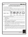
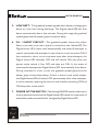
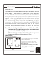
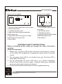
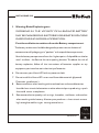
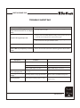
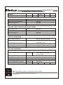
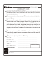
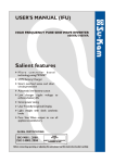
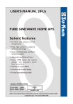
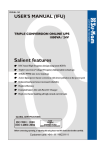
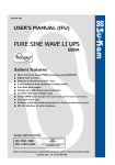
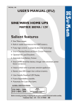
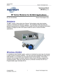
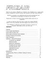
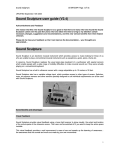
USER'S MANUAL (IFU)
DIGITAL HOME UPS
Salient features
7 Micro controller based
technology using MOSFETs
7 Fuzzy logic control - a unique &
advanced technology
7 Smart overload sense and short
circuit protection
7 Automatic low battery cutout
7 PWM controlled efficient fast
charging
7 Great power saving
7 User-friendly LED indication
GLOBAL CERTIFICATIONS:
R&D
Recognised
ISO 14001:2004
MINISTRY OF SCIENCE & TECHNOLOGY
GOVERNMENT OF INDIA
Before connecting, operating, or adjusting this unit, please read this instruction booklet carefully .
Customer Care : +91 124 4170561-566
DIGITAL HOME UPS
Dear Customer,
Congratulation as choosing Su-Kam Digital Home UPS! This Digital Home UPS
has been developed using state-of-the-art Micro controller based technology.
Some of the distinguishing features of the Su-Kam Digital Home UPS :
7 Micro controller based
7 PWM controlled efficient fast
7 Fuzzy logic control-a unique &
7 Great power saving
7 User-friendly LED indication
technology using MOSFETs
advanced technology
7 Smart overload sense and short
charging
circuit protection
7 Automatic low battery cutout
This manual will help you to better understand your Digital Home UPS , increase
your convenience in using it and maximize its benefits for you..
Feel free to contact our authorized dealer or us at [email protected] or
visit our website www.su-kam.com anytime for any clarification or more
information.We value your suggestions and comments. Su-Kam is committed to
continual product improvement and feel the best way to accomplish this task is by
listening our valued customers. This commitment gets strengthened every time
you buy a Su-Kam product.
We appreciate the support you have shown us through the purchase of our
product. Please read this manual to become familiar with its features and various
applications.
Regards,
Su-Kam Power Systems Limited
Introduction
REV. 08-02-07
DIGITAL HOME UPS
CONTENT
]
KNOWING YOUR HOME UPS
(A) FRONT PANEL...........................................................................................1-2
(B) BACK PANEL................................................................................................3-4
]
IMPORTANT SAFETY INSTRUCTIONS...................................................4-5-6
]
SPECIAL NOTICES...............................................................................................6
]
TROUBLE SHOOTING.......................................................................................7
]
TECHNICAL SPECIFICATIONS....................................................................8-9
]
WARRANTY CARD............................................................................................10
Contents
REV. 08-02-07
DIGITAL HOME UPS
KNOWING YOUR HOME UPS
Now lets begin the journey to explore various aspect of your Su-Kam Digital
Home UPS. Welcome aboard!
In its most basic form, an Digital Home UPS transforms Direct Current (DC) to
Alternating Current (AC). The battery bank with the Digital Home UPS acts as a
reservoir to ensure continuous supply of power whenever mains supply from
utility power is not available.
+
FRONT VIEW:
MAINS ON
-
INV. ON
+
CHARGE
OVER LOAD
-
BATT. LOW
OR
MAINS ON
INV. ON
BATT. CHRG.
OVER LOAD
BATT. LOW
On the front panel of the digital Home UPS there is one Power Active switch and
a graphical symbol panel, for indications.
1.
MAINS ON : This white graphical symbol, when lit, indicates that incoming
mains is available.
2. INV. ON : This white graphical symbol shows that incoming mains is not
available and the output is from Home UPS.
3. BATT. CHARGING / CHARGED : This white graphical symbol, shows
that the incoming mains is available and simultaneously the battery is also
being charged . This white graphical symbol, glows intermittently during
charging and glows continuously when battery is charged.
4. FUSE BLOWN : Mains fuse blows off when the Home UPS is operating on
mains and the load connected through the Home UPS exceeds the specified
limits prescribed for the Home UPS. In this case, at once reduce the extra
load and replace the glass fuse given at back to restore the mains line. During
this stage, the Mains ON graphical symbol, glows intermittently with buzzer
beeps .
Front
Panel
REV. 08-02-07
DIGITAL HOME UPS
5. LOW BATT. : This graphical symbol, appeals when battery voltage goes
down to a low limit during discharge. The Digital home UPS will shut
down automatically after a few minutes. During this stage the graphical
symbol glows and the buzzer gives continuous beep.
6. O.L. / SHORT CIRCUIT : This graphical symbol, shows that either
Short circuit has occurred or there is overload on the Home UPS. The
Digital Home UPS resets itself automatically and makes 8 attempts in
case of overload and 4 attempts in case of short circuit to switch ON. If
the overload or short circuit continues even after these attempts, the
Digital Home UPS switches OFF and will switch ON only after the
power active switch is first OFF and then put ON. In the event of
unsuccessful attempts the Digital Home UPS automatically shuts down.
During overload or short circuit the graphical symbol glows and the
buzzer gives a intermittent beep. If there is short circuit at the output,
the Digital Home UPS will switch OFF permanently after a few attempts.
It can be reset by repairing the short circuit and then switching OFF and
ON the power active switch.
7. POWER ACTIVE SWITCH : The latching ON/OFF switch in the front is
to be pressed to ensure that the Digital Home UPS switch on in the event of
mains failure and connected load is energised by Digital Home UPS.
Front
Panel
REV. 08-02-07
DIGITAL HOME UPS
BACK PANEL:
The Digital Home UPS has two battery wires coming out from the rear side,
a Fuse holder, 2 toggle switches, an output Socket and an input mains
or 3 way cable .We connect the two battery wires to the terminals of the
battery, the red coloured to positive terminal and the black coloured to the
negative. A three core input cable has to be used to connect the home
UPS to incoming AC Mains. Ensure that incoming phase (or line) is
connected to line (Red wire) neutral is connected to neutral (Black Wire)
and earth is connected to earth (Green Wire). After this the output is
connected through the output socket at the rear of the Home UPS.
Note :1. Position the Toggle Switch(4) at the rear panel of the Home UPS to
Narrow window (UPS) mode if you want to run PC load otherwise always
place the switch to Wide Window(INV) mode.
2. Position the Toggle switch(5) to HC mode during frequent power cuts
for fast charging of battery otherwise place to NC mode.
REAR VIEW:
Back panel view 600&800VA
INV
4
UPS
OUTPUT
NC
5
HC
1. 3 Core Input Wire (Mains Input for Home UPS).
2. 15A AC Output Socket.
3
3. F6.3A/250V (Fast Blow) Fuse upto 800VA.
4. Toggle Switch Narrow Window(UPS) / Wide
+
6
_
Window (INV) mode.
5. Toggle Switch Normal Charging Current (NC)/
2
(RED)
(BLACK)
BATTERY WIRES
1
High Charging Current (HC) mode
6. Battery Wires.
BLACK
RED
GREEN
REV. 08-02-07
Back
Panel
DIGITAL HOME UPS
Back panel view 400VA
Back panel view 1400VA
INV
4
UPS
Input
OUTPUT
1
INV
4
UPS
OUTPUT
NC
5
HC
3
N
E
L
+
6
+
_
2
2
(RED)
(BLACK)
(RED)
3
1
5
_
(BLACK)
BATTERY WIRES
BLACK
RED
GREEN
1. Input Terminal Block (Mains Input for Home UPS).
1. 3 Core Input Wire (Mains Input for
2. 15A AC Output Socket.
Home UPS).
3. T10A/250V (Slow Blow ) Fuse.
2. 6A AC Output Socket.
4. Toggle Switch Narrow Window (UPS)/ Wide
3. F6.3A/250V (Fast Blow).
Window (INV) mode.
4. Toggle Switch Narrow Window(UPS)
5. Toggle Switch Normal Charging Current (NC)/
/ Wide Window (INV) mode.
High Charging Current (HC) mode
5. Battery Wires.
6. Battery Wires.
IMPORTANT SAFETY INSTRUCTIONS
Before proceeding further kindly go through the safety instructions
carefully.
General Precautions:
1. Before using the Home UPS read all instructions and cautionary markings
on the Home UPS, the Batteries, all appropriate section of this instruction
manual.
2. Do not expose Home UPS to rain, liquids of any type. The Home UPS is
designed for interiors only.
3. Do not disassemble the Home UPS, take it to a Su-Kam Engineering
Service Centre when service or repair is required. Opening by unqualified
personnel entails electric shock or fire hazard.
4. To reduce risk of electric shock, disconnect all wiring before cleaning.
Safety
Instructions
REV. 08-02-07
DIGITAL HOME UPS
5. Warning-Risk of Explosive gases
WORKING IN THE VICINITY OF A LEAD ACID BATTERY
MAY BE DANGEROUS. BATTERIES GENERATE EXPLOSIVE
GASES DURING NORMAL OPERATION.
Provide ventilation to outdoors from the Battery compartment.
The battery enclosures should be designed to prevent accumulation and
concentration of hydrogen gas in“pockets’’ at the top of the compartment.
Vent the battery compartment from the highest point. A sloped lid can also be
used to direct the flow to the vent opening location. To reduce the risk of
battery explosion, follow all the instructions of batteries supplier or any
equipment you intend to use in the vicinity of batteries.
6. Do not cover your Home UPS with any cover or cloth.
7. Do not install this Home UPS on or near flammable materials (plywood,
Chemicals, gasoline etc.).
8. Be extra cautious when working with metal tools on and around batteries.
It could short-circuit the batteries or other electrical parts, producing a spark
that could cause an explosion.
9. Remove conductive jewelry such as rings, bracelets, necklaces, and watches
when working with a battery. A battery can produce a short-circuit current
high enough to weld a ring or causing severe burns.
Safety
Instructions
REV. 08-02-07
DIGITAL HOME UPS
IMPORTANT PRECAUTIONS:
The output side of the Home UPS AC wiring should never be connected to a
generator or incoming utility power. This condition is far worse than a short
circuit. If the unit survives this condition, it will shut down until correction is
made.
Note : Never disconnect the battery cables while the Home UPS is delivering
power or battery charger is operating.The Power Active Switch has no effect on
the charger; it turns off only the power output during backup mode.To disconnect
the batteries for service:
(a) turn off the power switch.
(b) disconnect all AC power.
(c) disconnect all the battery cables.
Special Notices:
! Do not switch on the heavy load TV, Refrigerators, Motor, Cooler, etc when
Home UPS is running on battery backup and is in UPS mode. This may
cause rebooting of your computer.
!
Avoid connecting the stabilizer between utility power and Home UPS. The
AVR of stabilizer may cause your computer to reboot.
!
We recommend that you have point to point wiring of the Home UPS.
!
GROUNDING INSTRUCTIONS: This Home UPS must be
connected to a grounded, permanent wiring system.
Special
Notices
REV. 08-02-07
DIGITAL HOME UPS
TROUBLE SHOOTING
Symptoms
Rectifications
Reduce the load and replace the glass fuse of specified ratings given at
rear side of the home UPS.
Main power is coming. Home UPS
shows mains fuse blown on its display
panel.
No power during backup mode.
(1) Check if low battery graphic symbol is glowing, switch OFF the Home
UPS by power active switch. Allow the battery to charge when the mains is
resumed before running the Home UPS on battery again.
(2) Check if overload/short circuit graphic symbol is glowing.Reduce load
and reset theHome UPS by Power Active switch.
Home UPS does not operate.
Check the battery connections and the mains connections
Home UPS trips frequently at backup
Reduce the load and restart Home UPS through Power Active Switch.
mode.
System shuts down after
20 sec no display at all
Remedy
Problem
Symptoms
There is no output power (1) Low Battery.
Check condition of batteries and recharge.
(2) Loose or corroded batt. Connections.
Check and clean all connections.
(3) Loose AC output connection.
Check all AC output connections.
Output of home UPS is wired back to its
Check for proper AC input and output wiring.
own input.
Low/High AC output Measuring with the wrong type Voltmeter.
Meter must be a true RMS reading meter.
voltage
Low surge power
Weak batteries, battery cable too long.
Refer to cable and battery recommendations
in this manual.
REV. 08-02-07
Trouble
Shooting
DIGITAL HOME UPS
TECHNICAL SPECIFICATIONS
MODEL
CAPACITY
FRENDY
SONIK
400VA/12V
600VA/12V
COSMIC/
COSMIC DX
800VA/12V
SWAN
TRUSTY**
800VA/12V 1400VA/24V
VOLTAGE LIMITS (NARROW WINDOW-UPS MODE)
Mains A.C. Low cut
Mains A.C. Low cut Recovery
Mains A.C. High cut
Mains A.C. High cut Recovery
185 ± 5V
190 ± 5V
265 ± 5V
260 ± 5V
VOLTAGE LIMITS (WIDE WINDOW-INV MODE)
Mains A.C. Low cut
Mains A.C. Low cut Recovery
Mains A.C. High cut
Mains A.C. High cut Recovery
105 ± 5V
120 ± 5V
285 ± 5V
275 ± 5V
OUTPUT PARAMETER
Mains Output Frequency
Output Frequency
Same as Input (45 Hz-55Hz)
50.0 Hz. ± 0.1 Hz
Output Voltage with Full Load
Overload
Short Circuit protection
220V/200V ± 10V
Above 110%
>250% Load (Few msec)
BATTERY CHARGING
Microprocessor based Controlled SCR charging with Soft start over full range of mains 130V to 290V
Maximum Charging Current Limit
Charging Boost Voltage
Charging Float Voltage
Battery Lower Voltage Limit
Recommended Battery capacity
Number of Batteries
Technical
Specifications
9.0 ± 1.0 Amp,11 ± 1.0 Amp
For HC mode
13.9 V ± 0.2 V per battery
13.6 V ± 0.2 V per battery
10.0 V ± 0.2 V per battery
6.0±1.0 Amp
80 AH-120AH
1
135AH-180AH
1
1
Note: Specifications subject to change without prior Notice
REV. 08-02-07
1
2
DIGITAL HOME UPS
MODEL
CAPACITY
FRENDY
SONIK
400VA/12V
600VA/12V
COSMIC/
COSMIC DX
800VA/12V
SWAN
TRUSTY *
800VA/12V 1400VA/24V
TECHNOLOGY
Microcontroller based state-of-the-art technology using MOSFETs.
Fuzzy Logic control Technology.
ENVIRONMENT
Storage Temp.
Operating Temp.
Humidity.
Dimension (W XDX H) in mm
Weight(Kg)
0-50°C
0-40°C
0-90% Non-condensing
148X250X220 272X275X122 300X300X130 272X275X122 392X310X170
8.0Kg
9.20Kg
10.10Kg
9.50 Kg
17.65 Kg
* Trusty don’t have dual charging current setting (NC/HC) options.
Note : Specifications subject to change without prior notice.
REV. 08-02-07
Technical
Specifications
(9)
DIGITAL HOME UPS
WARRANTY CARD
SU-KAM POWER SYSTEMS LIMITED warrant to the original purchaser
provided the product is still in possession of and used by the original purchaser
from the date of purchase.
The warranty stands on all parts (except LED’s, switches and external body) for a
period of 2 years.
The warranty will not apply to defects arising in company’s opinion by reasons of
accident, abuse, misuse, neglect improper installation (if not undertaken by the
company or its representative), fire, flood, or other act of GOD and any other
natural calamities and any other unauthorized repairs done or carried out will
have to be borne by the purchaser. The problem of fuse blown will not be
included in the warranty of the product. The services given for the same will be
paid service.
The company in no way will be held liable for any loss or injury or damage
caused to life or property or death and disability caused to any form of life for
any reason whatsoever.
All disputes are subject to jurisdiction of Delhi only.
Model No.
: ......................................................................
Serial Number
: ......................................................................
Name of Purchaser
: ......................................................................
Address
: ......................................................................
Date of Purchase
: ...................................
Dealer’s Name
: ...................................
DEALER'S STAMP
Warranty
(10)
REV. 08-02-07
SU-KAM OFFICES ADDRESSES
Hyderabad
Plot No. 81, Syndicate Bank Colony
West Marredpally,
Secunderabad-500 026
Andhra Pradesh
Tel.: +91-40-32986828, 09347006004
9392004926
E-mail: [email protected]
Pune
Sr. No. 173/2 A, Shop No. 8 & 9,
Suryavanshi Towers
Behind Suyoba Karyalaya,
Bhekarainagar, Phursungi Taluka,Haveli
Pune 418302
Tel. : 020-32303900, 09370658684
E-mail: [email protected]
Indore
25, S D A Compound
Lasutia Thana, Devas Naka
Indore 452001
Madhya Pradesh
Tel: +91 9329560222, 9301157800
E-mail: [email protected]
Jaipur
Maruti Complex
D-221D,Bhaskar Marg, Bani Park
Jaipur
Rajasthan
Tel: 01413263200
E-mail: [email protected]
Bangalore
H.No.449, Ground Floor, 7 th Cross,
6th Main, MICO Layout, BTM II Stage,
Bangalore 560076
Karnataka
Tel.: 080-32961610, 09341444693
E-mail : [email protected]
Kolkata
75, Sarat Chatterjee road
Police Station, Lake Town
Kolkata 700089
West Bengal
Tel: +91 9433266573, 9339195150
E-mail: [email protected]
Ludhiana
Shop No. 15, Anmol Market
VIll. Daad, Pakhowal Raod
Ludhiana 141002
Punjab
Tel: +91 9317547976, 9317547978
E-mail: [email protected]
Patna
Flat No. G-1, Abhilasha Apartments
Justice Narayan Path, Nageshwar Colony
Boring Road, Patna 800001
Bihar
Tel: +91 9334121313, 9334842729
E-mail: [email protected]
Ghaziabad
13/7, Site No. 3
Meerut Road Industry Area
Near Uttam Toyota
Ghaziabad
Uttar Pradesh
Tel: +91-120-2713265, 9312091936,
9350191876, 9313777563
E-mail: [email protected]
SU-KAM POWER SYSTEMS LTD.
FACTORY : A) 64, DIC INDUSTRIAL AREA, BADDI, DISTT. SOLAN (H.P) INDIA
B) 196-C ,SECTOR-37,PH-VI,DISTT. GURGAON (HARYANA) INDIA
REGD.OFF.: WZ-1401/2, NANGAL RAYA , NEW DELHI-46
Chennai
14/50, Gandhi Road, Arumbakkam,
Chennai- 600106
Tamil Nadu
Tel.: 044- 32984497, 09344614009
E-mail : [email protected]
Vadodara
L-20/2, Por-Ramangamdi
Indl Estate (GIDC)
Por, NH-8
Vadodara 391243
Gujarat
Tel: +91 9377111634, 9327434081
E-mail: [email protected]
Ranchi
74/D, Plot No. 1
Park Road 3, Ashok Nagar
Ranchi 834002
Jharkhand
Tel: +91 9334196088, 9334842729
E-mail: [email protected]
Jammu
76/6, Trikuta Nagar
Near Mini Market
Jammu 180012
J&K
Tel: +91 9419310090, 9906310415
E-mail: [email protected]