1
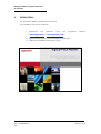
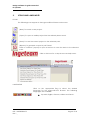
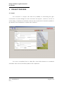
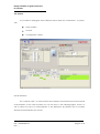
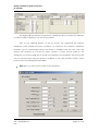
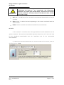
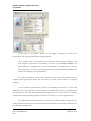
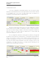
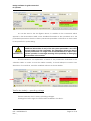
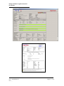
Design software for grid connected
PV systems
AAX2005IKE02 Rev. _
AAX2005IKL02_
USER’S MANUAL
INGECON® SUN PLANNER
Ref.: AAX2005IKL02
Rev.: _
Ingeteam Energy S.A
07/2008
Page 1 of 18
2009-10-28
Design software for grid connected
PV systems
Note: As a result of the company’s
commitment
to
an
ongoing
product
improvement program, Ingeteam S.A. reserves
the right to amend this document without prior
notice.
1.
Index
Page
INTRODUCTION ........................................................................................................................................ 4
1.1
Hardware and Software requirements ......................................................................................... 4
1.2
Usage regulations.............................................................................................................................. 4
2.
INSTALLATION........................................................................................................................................... 5
3.
ICONS AND LANGUAGES....................................................................................................................... 6
4.
PV SYSTEM DESIGN WITH THE INGECON® SUN PLANNER ................................................................. 7
5.
PROJECT PROCESS .................................................................................................................................. 8
6.
5.1
Project ................................................................................................................................................. 8
5.2
System ................................................................................................................................................. 9
5.3
Report ............................................................................................................................................... 16
PV panel database. ............................................................................................................................. 18
Ref.: AAX2005IKL02
Rev.: _
Page 2 of 18
Design software for grid connected
PV systems
Related documentation
CATÁLOGOS
Catálogo Comercial
Ingecon Sun
AAP0000IFA
Catálogo Técnico
Ingecon Sun
Monofásicos
Catálogo Técnico
Ingecon Sun Trifásicos
Catálogo Técnico
Comunicaciones
AAS2001IFA01
AAS2001IFA02
AAP2002IFA01
Catálogo Técnico
Ingecon Sun Hybrid
Catálogo Técnico
Ingecon Sun Monitor
AAR2001IFA01
AAR2001IFA02
AAP2005IFA01
Manual de Instalación
Ingecon Sun
Monofásicos
Manual de Instalación
Ingecon Sun
Trifásicos
Manual de Instalación
de Accesorios
Comunicación
AAP2000IKH01
AAS2000IKH01
AAP2002IKH
AAP2001IFA01
Catálogo Técnico
Ingecon Sun
Monofásicos
AAP2001IFA02
MANUALES
Manual de Instalación
Ingecon Hybrid
AAR2000IKH01
Manual de Usuario
Ingecon Sun
Monofásicos
Manual de Usuario
Ingecon Sun
Trifásicos
Manual de Usuario
Software de
Monitorización
AAP2000IKE01
AAS2000IKE01
AAP2002IKE01
Manual de Usuario
Ingecon Hybrid
Manual de Usuario
Ingecon Hybrid
Monitor
AAR2000IKE01
AAR2002IKE02
Ref.: AAX2005IKL02
Rev.: _
Page 3 of 18
Design software for grid connected
PV systems
1.
INTRODUCTION
This document refers to the PC program:
Ingecon®Sun Planner
The Ingecon® Sun Planner software has been conceived to serve as a design
guide for those users responsible for sizing grid-connected PV systems incorporating
Ingecon® Sun inverters.
1.1
Hardware and Software requirements
To use Ingecon® Sun the following are required:
1.2
•
PC with the Windows® XP operating system.
•
Adobe Acrobat 7.0 or higher.
Usage regulations
Copyright
The Ingecon® Sun Planner software is the property of Ingeteam, S.A.
Ingeteam is not liable for any direct or indirect damage caused by the
use of this program.
IMPORTANT
Ref.: AAX2005IKL02
Rev.: _
Page 4 of 18
Design software for grid connected
PV systems
2.
INSTALLATION.
The software shall be installed via the Internet.
The installation process is as follows:
1. Download
the
software
from
the
Ingeteam
website
(www.ingeteam.es or www.ingeteam.com ).
2. Execute file Setup.exe and commence installation.
3. Follow the installation instructions given.
Ref.: AAX2005IKL02
Rev.: _
Page 5 of 18
Design software for grid connected
PV systems
3.
ICONS AND LANGUAGES.
ICONS
The following icons appear in the Ingecon® Sun Planner main menu:
(New) To create a new project.
(Open) To open an earlier project that has already been saved.
(Save) To save the current project on the selected path.
(Reports) To generate a report in pdf format.
Click on “informe” (report) to open a text box to save the data to the selected
path.
Click on this icon for a drop down user help menu.
LANGUAGES
Click on the appropriate flag to select the desired
language for the Ingecon® Sun Planner. The following
languages are available:
Spanish, English, German, Italian and French.
Ref.: AAX2005IKL02
Rev.: _
Page 6 of 18
Design software for grid connected
PV systems
4.
PV SYSTEM DESIGN WITH THE INGECON® SUN PLANNER
The aim of the Ingecon® Sun Planner is to automatically provide the PV
configuration that is best suited to the Ingecon ® Sun inverter selected, based on the
operating conditions indicated in the following table.
Extreme operating temperatures
Irradiance
Cell temperature from -10ºC to +70ºC
1000 W/m2
Although the software proposes a PV system configuration, the user also has the
possibility of manually creating an alternative solution, and can modify the extreme
operating temperatures and decide whether the system voltage and current values
are adequate. However, it is only possible to analyse the performance of module
configurations for irradiance levels of 1000 W/m2.
When designing the PV system, the user should also take into account
any specific characteristics of the PV system in question given the fact
that the system automatically sized by the Ingecon® Sun Planner does
not do so. Such characteristics include: voltage drops along the wiring,
shadows, system cooling, length, latitude and PV array tilt angle.
IMPORTANT
Ref.: AAX2005IKL02
Rev.: _
Page 7 of 18
Design software for grid connected
PV systems
5. PROJECT PROCESS.
5.1. Project
The “Proyecto” or Project tab offers the possibility of customising the gridconnected PV system design for each customer and project. However, for the PV
system sizing, completion of the fields under this tab is optional; it is therefore possible to
go directly to the "Instalación" or system tab, if desired.
The user is completely free to solely fill in those fields desired or considered
advisable. There are no mandatory fields to be completed.
Ref.: AAX2005IKL02
Rev.: _
Page 8 of 18
Design software for grid connected
PV systems
5.2. System.
It is possible to distinguish three different areas within the “Instalación” or system
tab:
Solar module.
Inverter
Configuration values.
SOLAR MODULE
The “módulo solar” or solar module area displays the electrical and mechanical
characteristics of the solar modules. As can be seen in the following figure, there is a
tab to select the type of characteristics to be displayed. By default, the PV module
electrical characteristics are shown.
Ref.: AAX2005IKL02
Rev.: _
Page 9 of 18
Design software for grid connected
PV systems
The Ingecon® Sun Planner incorporates a database which includes the different
module models available on the PV sector market.
Due to the ongoing growth of the PV sector, the Ingecon® Sun Planner
database could possibly become outdated. To overcome this problem, database
updates can be downloaded when the button is enabled with the text “Hay una
versión más reciente en la base de datos” (There is a more recent version in the
database). For system sizing with a model not included in the database, this new model
can be incorporated using the buttons available in the solar module section. These
buttons have the following functionalities:
New: New. To add a new module to the database.
Ref.: AAX2005IKL02
Rev.: _
Page 10 of 18
Design software for grid connected
PV systems
IMPORTANT
The fields: “Coeficiente de temp.Pot”, “Coeficiente de temp.Voc” and
“Coeficiente de temp.Isc” are, respectively, the temperature
coefficients for: Power; open circuit voltage; and short-circuit current.
All these coefficients should be entered as an absolute value, in other
words, with no sign.
Edit: Edit. To modify any of the electrical or mechanical characteristics of any PV
module.
Clear: Clear. To delete the data appearing on the screen associated with the
solar module.
Delete: Delete. To delete the selected module from the database.
INVERTER
In the “Iinversor” or inverter area, the Ingecon® Sun inverter desired for the PV
system is selected. The inverter characteristics are then shown: the “DC” and “AC” tabs
for the electrical characteristics and the "Mecánica" tab for the mechanical
characteristics.
To delete the data associated with the Inverter section of the screen, click on
the clear button: Clear.
Ref.: AAX2005IKL02
Rev.: _
Page 11 of 18
Design software for grid connected
PV systems
If you look at the figures above, in the figure showing the inverter DC
information, the following warning message appears:
“Si su campo solar no es flotante por conexión a tierra del polo positivo o del
polo negativo del campo fotovoltaico, contacte con INGETEAM ENERGY S.A
para validar su configuración” (If your solar field is not floating due to the PV
array negative or positive pole being grounded, contact INGETEAM ENERGY SA
in order to validate your configuration).
For correct operation, some solar modules need to have their positive pole or
negative pole grounded. When this connection is made, the PV array is no longer
floating.
If the module specifications require a non-floating connection for the solar
array, then the Ingecon® Sun inverters require an additional kit that is not included with
the equipment and must be requested from Ingeteam S.A. For this reason, the above
mentioned warning message indicates that it is necessary to contact Ingeteam S.A.
The Ingecon® Sun Planner does not include the data sheets provided by the
solar module manufacturers and which indicate whether the solar array should have a
non floating configuration.
Ref.: AAX2005IKL02
Rev.: _
Page 12 of 18
Design software for grid connected
PV systems
CONFIGURATION VALUES.
A PV array configuration automatically appears once the panel has been
selected in the SOLAR MODULE area and the Ingecon® Sun inverter has been selected
in the INVERTER area, or vice versa. The figure below shows an example of a
configuration automatically made by an Ingecon® Sun 5.
Although the Ingecon® Sun Planner gives a PV array configuration by default,
the user always has the possibility of modifying the number of panels connected in
series and the number of strings, in addition to the extreme temperature conditions for
which the system is to be sized, which by default are for a solar module cell
temperature ranging from + 70ªC to - 10ºC.
For any configuration whatsoever, whether given by default by the Ingecon®
Sun Planner or user-created, the “Observaciones” or observations section provides an
analysis of the quantities of various PV array variables, indicating whether there is any
possibility of damaging the PV modules and / or the inverter. Below it is possible to see
how, when the extreme design temperature for the cell is changed to -20ºC, for the
configuration of the figure shown above, a message appears indicating that this
situation would cause damage to the inverter.
Ref.: AAX2005IKL02
Rev.: _
Page 13 of 18
Design software for grid connected
PV systems
As can be seen in the two figures above, in addition to the comments which
appear in the observations table, more detailed information is also provided as to the
potential repercussions that the various parameter quantities could have on the inverter
in the specific PV system sizing.
IMPORTANT
In the observations section, in order to see whether there is any
additional information for any of the PV system parameters, move the
mouse pointer over the comments. The information shown for the PV
system parameters can range from recommendations to improve the
system operation to messages warning of the possibility of damaging
the modules or the inverter.
Provided below is an explanation of each of the parameters indicated in the
valuation table. In order to read the table correctly, it should always be read in two
directions. For each line, read the enabled columns as shown below.
Tensión de trabajo – operating voltage
This line indicates the PV array operating voltages.
Starting from left to right, the information enabled in this line is:
Ref.: AAX2005IKL02
Rev.: _
Page 14 of 18
Design software for grid connected
PV systems
Limite mínimo inversor - Minimum inverter limit: This parameter indicates the
minimum value of the MPP voltage range for the inverter.
VMPP +70ºC: This is the MPP voltage shown by the PV system sized at a cell
temperature of 70ªC and 1000 W/m2. It is possible to analyse the MPP voltage for
a value other than + 70ªC for the cell, which is the value given by default by the
Ingecon® Sun Planner for the automatic configuration.
VMPP +25ºC: MPP voltage of PV system sized at a cell temperature of 25 ºC for
and 1000 W/m2.
Voc -10ºC: This is the open circuit voltage shown by the PV system sized at a cell
temperature of -10 ºC and 1000 W/m2. As can be seen in the table, it is possible
to analyse the open circuit voltage Voc for a cell temperature value other than
-10 ºC , which is the value given by default by the Ingecon® Sun Planner for the
automatic configuration.
Límite máximo - Maximum limit: This column is sub-divided into the Inverter and
module. This sub-division enabled will show the most restrictive voltage value in
order not to damage the module or inverter.
Observaciones - Observations: A check is made of the PV system values:
VMPP+70ºC, VMPP+25ºC, and Voc -10ºC to ensure their adequacy. Should
different temperature conditions be taken for the extreme values, such as,
VMPP+80ºC and Voc -20ºC, the observations are also made for these operating
conditions.
Vmax, Sistema – Vmax, System
This line checks that the PV array configuration does not have a voltage that
could damage the PV modules or the inverter.
Límite máximo – maximum limit: This is subdivided into Inverter and Module. In
this case, the maximum voltage values are given, going upwards, that the PV
system elements can withstand, in other words the module and inverter, or vice
versa.
Ref.: AAX2005IKL02
Rev.: _
Page 15 of 18
Design software for grid connected
PV systems
Observaciones - observations: A check is made to ensure that the PV system is
within the maximum voltage limits of the elements making up the system.
Imax, Sistema – Imax, System
The line corresponding to Imax, System is responsible for analysing the direct
current value which the PV array delivers to the inverter.
Imax,Sistema – Imax System: This parameter indicates the short-circuit current of
the PV array at a cell temperature of 25ºC and 1000 W/m2.
Observaciones - observations: The idea of the Imax, System line is to verify that
at conditions of 25ºC and 1000 W/m2 the maximum permitted PV inverter input
current is not exceeded.
Factor dimensionado - Sizing factor
In the Ingecon® Sun Planner, the sizing factor line aims to show the ratio
between the size of the PV system and the rated power of the Ingecon® Sun
inverter used.
Factor dimensionad0 - Sizing factor: The sizing factor (FD) is defined as the ratio
between the peak power of the PV array at a cell temperature of 25 ºC and
1000 w/m2 and the AC rated power of the inverter.
Observaciones - observations: Here the FD value is analysed in order to avoid
excessively high or low values.
5.3. Informe - Report.
The report tab displays a compilation of the information provided under the
Project and System tabs. By clicking on the “Informes” or report icon in the main
menu, a PDF document is generated with all the information appearing on
screen with regard to the configuration of the PV system obtained.
Ref.: AAX2005IKL02
Rev.: _
Page 16 of 18
Design software for grid connected
PV systems
Ref.: AAX2005IKL02
Rev.: _
Page 17 of 18
Design software for grid connected
PV systems
6. PV PANEL DATABASE.
The technical data for the PV modules included in the Ingecon® Sun Planner
were obtained from the Solar Module 2008 Professional database of the Photon
magazine. Ingeteam is in no way liable for any data inaccuracy.
Ref.: AAX2005IKL02
Rev.: _
Page 18 of 18
MANU
AL DE
USUA
RIO
INGEC
ON®
SUN
PLANN
ER
Avda. Ciudad de la Innovación, 13
31621 Sarriguren (Navarra)
Tel +34-948 288 800
Fax +34-948 288 801
http://www.ingeteam.com
Design software for grid connected
PV systems
Ingeteam,
S.A.
www.ingeteam.com
Ref.: AAX2005IKL02
Rev.: _
Page 19 of 18