1
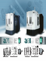
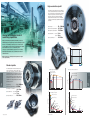
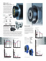
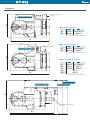
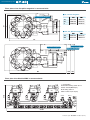
Makino Milling Machine Co., Ltd.
Head Office
3-19 Nakane 2-chome, Meguro-ku, Tokyo-to 152-8578, Japan Tel: +81(0)3-3717-1151 Fax: +81(0)3-3725-2105 URL http://www.makino.co.jp
International Operation Department Atsugi Works
4023 Nakatsu, Aikawa-machi, Aiko-gun, Kanagawa-ken 243-0303, Japan Tel: +81(0)46-284-1536 Fax: +81(0)46-286-4334
Makino J Co., Ltd.
4007 Nakatsu, Aikawa-machi, Aiko-gun, Kanagawa-ken 243-0303, Japan Tel: +81(0)46-286-8350 Fax: +81(0)46-286-8385 URL http://www.makinoj.co.jp/
Makino Inc.
Makino Asia Pte Ltd
7680 Innovation Way, Mason, Ohio, 45040, U.S.A.
Tel: +1-513-573-7200 Fax: +1-513-573-7360 URL http://www.makino.com
2 Gul Avenue, Singapore 629649
Tel: +65 68615722 Fax: +65 68611600 URL http://www.makino.com.sg
Makino Inc. Makino Die/Mold Technologies Center (Detroit)
Makino China Co., Ltd.
2600 Superior Court, Auburn Hills, MI 48326 U.S.A.
Tel: +1-248-232-6200
No.2, Mu Ye Road, Yushan Town, Kunshan City, 215 316, China
Tel: +86-512-5777 8000 Fax: +86-512-5777 9900 URL http://www.makino.com.cn
Makino GmbH/Makino Europe GmbH (Hamburg)
Makino India Private Limited
Essener Bogen 5, 22419 Hamburg, Germany
Tel: +49 40 29809-0 Fax: +49 40 29809-400 URL http://www.makino.de
No.11, Export Promotion Industrial Park, Whitefield Road, K.R.Puram,
Bangalore 560 066, India
Tel: +91-80-6741 9500 Fax: +91-80-6741 9523 URL http://www.makinoindia.co.in
Makino GmbH (Kirchheim)
Kruichling 18, 73230 Kirchheim unter Teck, Germany
Tel: +49 7021 503-0 Fax: 49 7021 503-400 URL http://www.makino.de
Makino France S.A.S.
Bâtiment Ronsard Hall A Paris Nord 2 22, Avenue de Nations
CS 45045 Villepinte 95912 Roissy Charles De Gaulle Cedex France
Tel.: +33 1 787843-20 Fax: +33 1 787843-43 URL http://www.makino.fr
Makino Italia S.r.l.
Strada privata delle Orobie, 5 Localitá Santa Maria in Campo 20873 Cavenago
Brianza (MB), Italia
Tel: +39 02 9594 82-90 Fax: +39 02 9594 8240 URL http://www.makino.it
Makino Iberia s.l.u.
C/ Agricultura,16-18, 2° 4ª, 08320 El Masnou,Barcelona,Spain
Tel: +34 93 555 9515
PT Makino Indonesia
Gading Mediterania Residences RK.008/D
Jl. Boulevard Bukit Gading Raya, Kelapa Gading Jakarta Utara 14240 Indonesia.
Tel: +62 2130041022 Fax: +62 2130041023
Makino Technology Center Sdn Bhd
No. 11,Jalan Teras 2 Kawasan Industri Teras,
43300 Balakong Selangor,Darul Ehsan Kuala Lumpur Malaysia
Tel: +603 89611973 Fax: +603 89611971
Makino (Thailand) Co., Ltd.
57/23 Moo 4, Ramintra Road, km 2, Anusaowaree, Bangkhen, Bangkok 10220 Thailand
Tel: +66 2 971 5750 Fax: +66 2 971 5751 URL http://www.makino.com.th
Makino Asia Pte Ltd Vietnam office
Makino s.r.o.
9th Floor, Vinaconex Building 47 Dien Bien Phu Street, Da Kao Ward District 1,
Ho Chi Minh City Vietnam
Tel: +84 839104832 Fax: +84 839104994
Tuhovská 31, 83106 Bratislava, Slovakia
Tel: +421 2 4961 2100 Fax: +421 2 4961 2400 URL http://www.makino.sk
Makino Korea Co., Ltd.
Makino Europe GmbH (Moscow)
335-12, Doksan-Dong, Geumcheon-Gu, Seoul, Korea
Tel: +82(0)2-856-8686 Fax: +82(0)2-856-8555 URL http://www.makinoseoul.co.kr
4th Dobrininsky Pereulok 8 Office C13-02 119049 Moscow Russian Federation
Tel: +7 495 9 89 82 20 Fax: +7 495 9 89 82 21
*The specifications, figures and overview of the products, peripheral device and accessories (includes options) in this catalogue may be
changed without prior notice to incorporate improvements resulting from ongoing R&D program.
*The products displayed in this catalog include the optional specifications and equipment.
*The products include technical data and software, may be subject to the Foreign Exchange and Foreign Trade Control Law in Japan.
Prior to any re-sale, re-transfer or re-export of controlled items, please contact Makino to obtain any required authorization or approval.
Printed in Japan
M-360Eh 1301/1 (V-T-F)
Enhancing manufacturing capabilities
The challenge of achieving the highest possible productivity and quality within a limited time frame is
a constant objective for the shop floor.
Makino machining centers consistently meet these challenges by providing a rigid,
ideal platform for high efficiency / high accuracy machining in a wide variety of materials.
In addition, Makino's superior designs, such as one-piece way covers, provide industry leading reliability
with a focus on eliminating unplanned down time.
The enhanced manufacturing capabilities and exceptional reliability of Makino machining centers create
machining solutions that minimize per piece cost of production.
Machining performance
―――――――――――――――
[ Face mill ]
Case:
1
Case:
3
Machining performance
―――――――――――――――――
[ Face mill, End mill, Side milling cutter ]
Case:
Case:
High torque spindle* 1009 N.m (15%ED), BT50 (=&)
1
Metal removal rate: 896 cm3/min
Standard spindle 488 N.m (25%ED), BT50 (=&)
Metal removal rate: 792 cm3/min
Metal removal rate: 792 cm /min
■
■
■
Spindle speed ――――― 320
■
■
When machining at higher position on Y axis
■
Material ―――――――― Ductile
■
■
3
■
■
■
When machining around -200 mm on Y axis
■
3
cast iron (FCD450)
min-1
Feed rate ――――――― 1280 mm/min
Tool used ――――――― 200 mm diameter face mill
Axial depth of cutting ―― 4 mm
Radial depth of cutting ― 175 mm
Metal removal rate: 870 cm3/min
Material ―――――――― Ductile
cast iron (FCD450)
Spindle speed ――――― 630 min-1
Feed rate ――――――― 1320 mm/min
Tool used ――――――― 125 mm diameter face mill
Axial depth of cutting ―― 6 mm
Radical depth of cutting ― 100 mm
■
Material ―――――――― Carbon
■
Spindle speed ――――― 320
■
■
■
■
steel (S50C)
min-1
Feed rate ――――――― 1280 mm/min
Tool used ――――――― 200 mm diameter face mill
Axial depth of cutting ―― 4 mm
Radial depth of cutting ― 170 mm
* High torque spindle* is optional specification for a81
Photo: High torque spindle* (=&)
Case:
Photo: Standard spindle (=&)
4
Standard spindle 488 N.m (25%ED), BT50 (=&)
Material ―――――――― Ductile cast iron (FCD450)
Spindle speed ――――― 1200 min-1
Feed rate ――――――― 480 mm/min
Tool used ――――――― 40 mm diameter end mill
Axial depth of cutting ―― 50 mm
Radial depth of cutting ― 6 mm
■
■
■
■
■
■
Case:
Case:
!
4
Photo: Standard spindle (=&)
2
Standard spindle 488 N.m (25%ED), BT50 (=&)
Material ―――――――― Ductile cast iron (FCD450)
Spindle speed ――――― 800 min-1
Feed rate ――――――― 1440 mm/min
Tool used ――――――― 80 mm diameter face mill
Tool length ―――――― 275 mm
Axial depth of cutting ―― 4 mm
Radial depth of cutting ― 60 mm
■
Case:
■
■
5
Standard spindle 488 N.m (25%ED), BT50 (=&)
Material ―――――――― Ductile cast iron (FCD450)
Spindle speed ――――― 95 min-1
Feed rate ――――――― 152 mm/min
Tool used ――――――― 150 mm diameter
■
■
■
■
■
■
■
■
staggered tooth side milling cutter
(16-insert)
Case:
2
Case:
Photo: Standard spindle (=&)
5
Photo: Standard spindle (=&)
*: optional specification
■
Axial depth of cutting ―― 4
■
Radial depth of cutting ― 15
mm
mm
"
Case:
Machining performance
――――――――――――
[ Boring, Reverse spot facer ]
6
Case:
8
Machining performance
―――――――――――――――――
[ Drilling, Tapping ]
Case:
8
Standard spindle 488 N.m (25%ED), BT50 (=&)
Metal removal rate: 679 cm3/min
Case:
6
Standard spindle 488 N.m (25%ED),
BT50 (=&)
Radical depth of cutting ― 5.0 mm
■
Material ―――――――― Gray
■
Spindle speed ――――― 935
■
■
cast iron (FC250C)
min-1
Feed rate ――――――― 187 mm/min
Tool used ――――――― 68 mm diameter insert drill
■
(one side)
■
■
■
■
Material ―――――――― Ductile
cast iron
(FCD450)
Spindle speed ――――― 207 min-1
Feed rate ――――――― 83 mm/min
Tool used ――――――― 200 mm diameter
and 400 mm length
boring bar
High torque spindle* 1009 N.m (15%ED), BT50 (=&)
Metal removal rate: 384 cm3/min
■
Material ―――――――― Ductile
■
Spindle speed ――――― 702
■
■
cast iron (FCD450)
min-1
Feed rate ――――――― 106 mm/min
Tool used ――――――― 68 mm diameter insert drill
* High torque spindle* is optional specification for a81
―――――――――――――――――
Case:
9
High torque spindle* 1009 N.m (15%ED), BT50 (=&)
Material ―――――――― Carbon steel (S50C)
Spindle speed ――――― 60 min-1
Spindle load ―――――― 35%
Feed rate ――――――― 270 mm/min
■
■
■
■
■
Tool used ――――――― M42-4.5
tap
High torque spindle* 1009 N.m (15%ED), BT50 (=&)
Material ―――――――― Ductile cast iron (FCD450)
Spindle speed ――――― 76 min-1
Spindle load ―――――― 25%
Feed rate ――――――― 342 mm/min
■
■
■
■
Photo: Standard spindle (=&)
Case:
Photo: Standard spindle (=&)
■
Tool used ――――――― M42-4.5
tap
■ Pitch
7
Measured position
Target values
Measured values
Errors
Holes ①―②
500.0000 mm
499.9992 mm
− 0.0008 mm
②―③
500.0000 mm
500.0011 mm
+ 0.0011 mm
③―④
500.0000 mm
500.0026 mm
+ 0.0026 mm
④―①
500.0000 mm
499.9992 mm
− 0.0008 mm
Accuracy
―――――――――――――――
[ Pitch and roundness ]
Actual values measured in Makino facility.
500
Case:
7
Standard spindle 488 N.m (25%ED),
BT50 (=&)
Radical depth of cutting ―
Roundness
①
(200 mm diameter)
②
10 mm
(one side)
Roundness
When machining at higher position on
Y axis
Material ―――――――― Ductile cast iron
(FCD450)
Spindle speed ――――― 282 min-1
Feed rate ――――――― 57 mm/min
Tool used ――――――― 65 mm diameter
back spot facer
(300 mm diameter)
500
■
■ Roundness
④
③
■
■
2.3 μm(CW)
■
2.8 μm(CCW)
The both were actual values measured in Makino facility.
■
Photo: Standard spindle (=&)
*: optional specification
1000 mm diameter
800 mm diameter
■ Pallet size ―――――――
■ Maximum pallet load ――――
■ Spindle taper hole ―――――
730 × 730 × 800 mm
360 degree (cont.)
500 × 500 mm
700 kg
7/24 No.50 taper
900 × 800 × 1020 mm
360 degree (cont.)
Pallet working area ―――― 630 × 630 mm
Maximum pallet load ―――― 1200 kg
Spindle taper hole ――――― 7/24 No.50 taper
■ Axis travels (X × Y × Z) ―――
(B) ―――
■
■
■
Maximum workpiece size
when pallet is changed.
Front view
1300 mm
(B) ―――
1000 mm
■ Axis travels (X × Y × Z) ―――
Maximum workpiece size
when pallet is changed.
Front view
Floor plan
Floor plan
Pallet
70
125
630 mm
3342 mm
2925 mm
100
60
2600 mm
3100 mm
500 mm
Pallet
M16-2
60
67 mm
3152 mm
4843 mm
M16-2
100
70
500 mm
3693 mm
5584 mm
125
630 mm
High acceleration spindle*
This spindle accelerates rapidly to its top speed within 2.4
seconds. Quick acceleration helps to reduce non-cut times.
This is especially critical on parts that require frequent tool
changes such as gear boxes, automotive engine and
transmission components. Supported by highly rigid
bearings with an inner diameter of 110 mm, this spindle
combines powerful machining capabilities with high speed
performance.
50 ∼ 10000 mim-1
Drive motor output 15min/cont. ― 22 / 18.5 kW
Bearing inner / outer diameter ―― 110 / 150 mm
Acceleration time ――10000 min 2.4 sec
5000 min 0.8 sec
Torque 25%ED/cont. ―――――― 226 / 143 N·m
■ Speed range ―――――――――
■
■
■
Aiming for the highest level of
machining capabilities
-1
-1
■
High speed machining using advanced machining centers has
dramatically improved productivity on the manufacturing shop floor.
It has also revolutionized production processes and the level of
accuracy attained. The key to high speed machining is the spindle,
which constitutes the essence of a machining center.
Three types of spindle variations, designed for use in a variety
machining fields under the severest conditions, are offered on
a71/a81 machines.
Acceleration/deceleration time
Speed range
10000 min-
1
5000 min-1
Makino products are continually advancing toward ever higher
levels of productivity.
Start
Standard spindle
The standard spindle is well suited to handling a wide
variety of machining jobs, ranging from high volume
cast iron parts for automobiles, construction equipment and
agricultural machinery to steel and aluminum components.
Providing powerful output of 35 kW, the standard spindle
achieves low vibration for superior machining quality. This
spindle delivers an optimum balance of impressive cutting
capabilities in many different machining fields, including
rigid taping at 3000 min-1.
■
■
22/430 min-(25%ED)
22/500 min-(15min)
1
18.5/720 min-(15%ED)
1
Power (kW)
30
30
(30min)
30
20
0
Photo: HSKspindle*
1
22
(15min)
18.5
2000
4000
6000
8000
20
15
10
0
10000
18.5
(cont.)
18.5
2000
4000
Speed (min-1)
500
6000
8000
488/430 min-(25%ED)
1
400
420/500 min-(15 min)
1
400
245/720min-(15%ED)
1
226/780min-(25%ED)
1
300
300
Torque (N.m)
140
117
200
121
(15min)
114
(30min)
95
(Cont.)
100
176
(15min)
200
143
(cont.)
88
70
58
72
100
60
26
22
28
23
0
2000
4000
6000
Speed (min-1)
*: optional specification
10000
Speed (min-1)
1
304/580 min--(cont.)
HSK-A100 holder
18.5/780 min-(25%ED)
25
(cont.)
22
10
-1
BT50 holder
High acceleration spindle characteristics
35
(15min)
-1
■
0.8sec
24
. sec
1
40
■ Speed range ――――――――――
■
■
Standard spindle characteristics
Power (kW)
20 ∼ 10000 mim-1
Drive motor output 15min/cont. ―― 35 / 25 kW
Bearing inner / outer diameter ―― 110 / 170 mm
Acceleration time ―― 10000 min 3.8 sec
5000 min 1.4 sec
Torque 25%ED/cont. ―――――― 488 / 304 N . m
■
Torque (N.m)
'
Stop
0.8sec
24
. sec
*: selectable specification
8000
10000
19
15
0
2000
4000
6000
Speed (min-1)
8000
10000
20000 min-1 spindle (core cooling)
20000 min-1 high power spindle (core cooling)
Makino’s unique spindle core cooling and under race lubrication
system is used to cool and lubricate this spindle. This advanced
system minimizes spindle thermal distortion during high speed
operation, maintaining stable high accuracy even over long hours
of continuous machining. Configured with this spindle, the
machine is ideally suited for deep pocket machining, common in
aluminum prototype and billet parts like vacuum chambers and
aerospace structural components. Additionally, the 20,000 minspindle has two variants; the 30kW high acceleration and a 55 kW
high power spindle delivering impressive machining performance.
1
■ Speed range ―――――――――― 50 ∼ 20000 mim
-1
■ Taper hole ――――――――――― HSK-A100
■ Drive motor output 10min/cont.
20000 min-1 spindle 20000 min-1 high power spindle
30 / 25 kW
55 / 50 kW
■ Acceleration time
20000 min-1 spindle
10000 min-1 6.5 sec
18000 min-1 16.5 sec
20000 min-1 22.0 sec
20000 min-1 high power spindle
4.4 sec
8.7 sec
10.4 sec
■ Torque
350 / 190 N.m
High torque spindle*
Spindle cooling and lubrication system
Makino’s spindle core cooling system circulates a
large volume of temperature controlled cooling oil
through the center of the rotating spindle to
Work size: 750 × 450 × 300 mm
provide direct internal cooling. This unique
Cooling oil
supply port
system cools the rigid spindle and large 100 mm
Cooling oil exit
inner diameter bearings, effectively minimizes
thermal distortion even during sustained high speed operation. The cooling oil first travels through the spindle core. The oil temperature
increases slightly as it moves through the core and circulates through the spindle stator housing. This creates an intentional temperature
difference between the spindle and housing. This consistent temperature difference and the superior cooling capability facilitate higher
spindle preloads ideal for heavy duty cutting even in ferrous materials. With under race lubrication, the cooled oil circulates through the
center of the spindle and then flows through holes in the inner race of the spindle bearings. Centrifugal forces distribute the oil from the inner
race throughout the bearing package; providing reliable lubrication even when the spindle bearings are rotating at high speed. (patented)
* available only when a81.
8,000 min- high torque spindle generates an impressive 1,009
N·m of torque. The powerful direct drive spindle motor features
large 120 mm inner diameter spindle bearings. Torque and
rigidity of this spindle make it ideal solution for large feature
heavy duty milling, drilling, boring and tapping of ferrous materials.
Gearless, direct drive spindle design also provides exceptionally
fast acceleration that minimizes non cut time in tapping and high
speed finishing applications.
1
■
20000 min-1 spindle characteristics
(10min)
30
25
(cont.)
25
22
20
15
■
44
10
40
■
32
8000
12000
16000
20000
0
4000
Speed (min-1)
8000
12000
16000
20000
Speed (min-1)
25
22
22
18.5
1000
2000
3000
4000
5000
6000
7000
8000
Speed (min-1)
1000
1009/350min-(15%ED)
1
900
901/392min-(25%ED)
1
800
600/392 min-(30min)
504/350 min-(cont.)
1
1
500
400
400
350
(10 min)
300
350(25%ED)
Torque (N.m)
300
44
200
600 min-1
12000
16000
Speed (min-1)
The all items on 11 page are the optional specifications.
29
26
100
190
(cont.)
43.7
15
100
11
10
8000
1
262
(10 min)
19
36
4000
200
20000
0
0
40
1600 min-1
100
185 / 1900 min-(30 min)
150 / 1900 min-(cont.)
1
300
1200 min-1
200
6500 min-1
238
(cont.)
2932 min-1
Torque (N.m)
0
Torque (N.m)
1200 min-1
6500 min-1
2932 min-1
600 min-1
4000
30
(cont.)
20
700
400
0
mim- 1
20
0
37
(30min)
30
kW
Bearing inner / outer diameter ―― 120 / 180 mm
Acceleration time 8000min-1 ――― 4.3 sec
4000min-1 ――― 1.5 sec
Torque 15%ED/cont. ―――――― 1009 / 504 N . m
1600 min-1
Power (kW)
22
■
55
(10min)
(cont.)
50
44(25%ED)
40
■ Drive motor output 15min/cont. ― 37 / 30
20000 min-1 high power spindle charcteristics
60
Power (kW)
30
High torque spindle characteristics
1
350min-(1
5%ED)
1
392min-(2
5%ED)
1
500min-(2
5%ED)
10
■ Speed range ―――――――――― 20 ∼ 8000
■
■
1900 min-1
350 / 238 N.m
1170 min-1
20000 min-1 high power spindle
25%ED/cont.
Power (kW)
20000 min-1 spindle
10 min/ cont.
1000
2000
3000
4000
5000
Speed (min-1)
26
23
4000
8000
12000
-1
Speed (min )
16000
20000
The all items on 12 page are the optional specifications.
6000
7000
8000
I
Rigid machine construction supports high acceleration and accuracy
Table
Feedrate
■ Rapid traverse ――― 50
Indexing table
■ Minimum index angle ―――――――――
■ Indexing time (90/180 degree) ―――
―――
1 degree
1.7 / 2.2 sec
1.9 / 2.7 sec
■ Cutting feed ―――― 50
m/min
m/min
Three points support
Rigidity is designed into the bed castings allowing a71
and a81 horizontal machining centers to sit on only three
points. Three point support reduces installation time and
eliminates periodic alignment maintenance. If shop floor
layouts need to change, a71 / a81 machines can be
quickly moved and returned to production.
NC rotary table*
■ Minimum index angle ―――――――――
■ Indexing time (90/180 degree) ―――
―――
■ Pallet positioning method
0.0001 degree
1.25 / 1.7 sec
1.6 / 2.3 sec
4 taper cone bushings
The pallet is positioned with high accuracy by four taper cones.
Each taper cone incorporates a clamping mechanism and pallets
are securely clamped with a total force of 10 tons.
The well-balanced support system enhances cutting capabilities in
the uppermost region on Y axis of the machining range.
Pallet
Ball screw cooling system
High speed movement of the ball
screws during long hours of operation
generates heat that can affect
accuracy and machining performance. To eliminate
thermal expansion, temperature controlled oil that’s
matched to the bed temperature is circulated through the
hollow ball screws.
◎ Reduction of non-cutting time for
high productivity
Previous machine
Cleaning air
Acceleration of spindle and axis feed (small)
Table
Faster feedrates also require quicker movement of the telescopic
covers that protect the slideways and ball screws. Constructed of a
single metal sheet, the X and Z axis covers enhance the reliability
of high speed
movement by
eliminating the risk of
damage due to the
incursion of chips. The
Y axis cover is driven
by a pantograph to
prevent collisions with
the other axis covers.
・
Time
GI.4 control
Same machining program as on the previous machine
Acceleration of spindle and axis feed (large)
Time reduction ①
ATC
ATC|B axis ATC|B axis
|rotation
|rotation
・
Time
Machining program using the parallel action function
to reduce the total time
Further time
reduction ②
ATC
◎ Machining time reduction function
ATC|B axis
|rotation
Speed
Telescopic covers
ATC|B axis
|rotation
ATC
Speed
When pallets are changed, the four taper cones on the table
discharge strong jets of air to prevent chips from getting on the
locating cones.
Speed
Cutting time
ATC
―――
B axis
rotation
ATC
―――
B axis
rotation
Total time reduction effect
=①+②
Time
Both machines are equipped with GI.4 control that maintains
excellent shape accuracy even at high cutting feeds. Four
control modes can be selected to match the machining job,
depending on whether speed or accuracy is the priority.
High accuracy
Radical Mode
High-Efficiency Mode
High-Accuracy Mode
Super-High Accuracy
M255
M251
M250
M252
(except for 5XR spec.)
High speed
High contouring accuracy facilitates process concentration
Machine parts have traditionally been produced
mainly in boring operations involving the use of
many tools, which has required considerable
time and effort for tool maintenance and
management. By contrast, contouring improves
work efficiency on the shop floor because holes
of different diameters can be machined
with one tool.
Machining operations that were
previously done on a lathe can be
replaced by a contouring process
executed on a machining center.
This concentration of machining
processes substantially reduces
setup time for greater efficiency.
Automatic workpiece measurement
Functions for reducing machining times can be specified with one M code command, such as simultaneous ATC operation and
table rotation or simultaneous execution of spindle stop/tool orientation and coolant off.
*: optional specification
Automatic workpiece
measurement boosts
productivity by minimizing
the need for operator
intervention to check and
adjust machined diameters.
I
High speed / reliable tool change and monitoring solutions
ATC rotating arm is supported at both ends
II
High speed ring type tool magazine substantially reduces tool
preparation time
1.7 sec
―――― 3.8 sec (MAS measurement system)
―――― 4.2 sec (MAS measurement system)
■ Tool to tool ―――――――
■ Chip to chip
Maximum tool size when tool is changed automatically
300 mm diameter
100 mm daimeter
300 mm diameter
60 mm diameter
BT50
BT50
600 mm
450 mm
645 mm
HSK-A100
300 mm diameter
100 mm diameter
300 mm diameter
60 mm diameter
515 mm
100
120
mm
Shank
a71
a81
BT50
450
600
HSK-A100*
540
690
Simple, high speed
ring type tool magazine
with high reliability (patented)
690 mm
540 mm
Tool size in the blue area has to be registered as APC prohibited tools.
Maximum tool length
HSK-A100
Tool size in the blue area has to be reagistred as APC prohibited tools.
Maximum diameter and weight, moment
Number of tool storage
Maximum diameter with conditions
without conditions
Maximum weight
Maximum moment
mm
kg
N·m
40 and 60*
115
300
20
19.6
97* and 137*, 186*, 242*, 300*
100
30
45
60 tools magazine for 30 kg weight (mass), 45 N·m is available as the optional specification only when a81. In detail, please contact Makino
representative staff in your area.
Broken tool sensor on ATC side*
Because broken tool detection is performed at the stand-by position of
the tool magazine, machining time is unaffected.
Retractable tool length
measurement device*
●
●
Metrol sensor (tool length can be measured)
MARPOSS sensor (tool length and diameter can be measured)
5.0/9.0 sec
60 tools magazine* ― 5.5/10 sec
■ Tool preparation time (minimum/maximum) ――― 40 tools magazine ――
Makino’s ring type tool magazine supports high speed
machining with smooth and fast indexing of the next
tool. Tool seek time as fast as 5 seconds means that
spindle wait time for the next tool is virtually eliminated.
After each machining operation the tools are returned to
their original pot location. Consistent tool location
simplifies periodic tool inspections and reduces the risk
of tools being put in the wrong pot.
Selection of tool changing speed
The automatic tool changer (ATC) can
be set to operate at three different
speed levels (normal setting is high
speed). Medium and low speed levels
can be selected while changing heavy
or unbalanced tools or when changing
the head used for making
measurements.
Medium speed levels
Low speed levels
Large capacity matrix tools magazine* (patented)
97, 137 tools magazine*
186, 242, 300 tools magazine*
#
$
(Photo: Metrol sensor)
The measurement head is
retracted to a lower position
than the table surface so that
there is almost no interfere with
the tool during machining.
*: optional specification
Tool loading station
■ Tool storage capacity ―――
97* and 137*, 186*, 242*, 300* tools
Servomotors are used in all axes to ensure quick operation.
Tool preparation time: 11 seconds at minimum
(only when 97 or 137 tools magazine)
Matrix tool magazines include a tool loading station for safe, efficient tool loading and inspection.
*: optional specification
II
Center chip trough can evacuate large volumes of chips effectively
from the machine during continuous machining
5XR spec.*
for 5 axis machining
Standard features ensure
reliable chip evacuation
8-nozzle coolant supply device
Overhead shower coolant system
● Base coolant (center trough)
● Chip conveyor (with drum filter)
●
●
Designed for zero chip incursion
Chip incursion
Air is discharged when tools are
changed to clean the spindle end
face and taper.
(HSK spindle)
End face
cleaning air
Taper
cleaning air
End face
cleaning air
End face cleaning air is discharged
until the tool holder is secured
tightly to the spindle end face.
End face
cleaning air
Photo: a81
Photo: a71
End face
cleaning air
5XR spec. (Tapped hole)*
5XR spec. (WHP clamp D)*
* Includes a function for confirming secure attachment
in the unlikely event chips get into the taper.
Chip conveyor
Makino offers a variety of chip
conveyor solutions designed for
efficient chip removal. Common types
are: Scraper, Double type (Scraper /
Hinge) and magnetic.Chip formation is
determined by the type of material and
manufacturing operations. Optimal
conveyor selection should be based on
the type of chips created. Consult your Chips
Makino representative for assistance
with conveyor selection.
Aluminum based
C axis
Less than 50 mm
①
②needles
Powders
③curls
360 degree
Larger than or equal to 50 mm
⑥
Large fragments
④
⑤
clumps
splinters
●
●
●
●
●
Steel based
●
●
●
●
●
Ductile cast iron
●
●
―
Inner
Base coolant
Hinge conveyor
Outer
Chip conveyor
(scraper)
Double chip conveyor
(scraper and hinge)
(standard specification)
(optional specification)
Please refer to the chip conveyor selection for detail criteria.
B axis
Through spindle coolant( 1.5 MPa / 2.2 MPa : 50 Hz / 60 Hz )
210 (-60 - +150) degree
Photo: a71
Photo: a81
1.5 MPa through spindle coolant is standard feature for substantially reducing hole machining time. (optional specifications: 3 MPa* or 7 MPa*)
Workpiece limitations size
Machne
A
B
2 sec
Coolant draw back (patented)
A
Diameter
B
C
Height
D
Weight
mm
a71
a81
400
500
700
850
C
380
455
D
193.649
183.4
150
520
kg
WHP clamp D*
WHP
a71
a81
The through spindle coolant system includes a unique coolant drawback circuit. The coolant stop command activates a draw back
system that vacuums excess coolant from the tool and spindle. This system reduces tool change time and minimizes coolant
contamination of the tool magazine.
*: optional specification
Spherical radius
Please contact Makino representative staff in you area of the
workpiece size dimension in detail when WHP clamp D* is selected.
*: optional specification
I
Machine uptime is enhanced by better maintainability and accessibility
Energy-saving effect of high speed machines
High speed machining reduces part cycle time and therefore reduces
power consumption. A comparison was made between a previous
machine and a71 for machining the same part. As seen at the right,
a71 showed only a slight increase in the rate of power consumption,
compared with its large benefit of reducing the machining time. This
indicates that a high speed machine consumes less power per product
or per unit time, thereby providing substantial energy savings.
Energy-saving measures
6864 W
Previous machine
Power consumption:
Energy saving of
6955 W
Excellent spindle accessibility
◎ Reduction of
· Adoption grease
Rate of power
consumption
6864 W
◎ Reduction of power consumption
· Use of a centralized coolant pump
(nozzles, overhead shower and base coolant)
· Activation of the chip conveyor
when the spindle is turning or when coolant is used
· Automatic power shutoff function
16%
=%
Power consumption:
Machining time
100 %
88.5m
84%
73.7m 88.5m
lubricant consumption
Improved operating manuals for
supporting effective machine use
Makino also provides improved manuals for explaining the
operation of the machine, programming, maintenance, parts
list and other aspects to ensure that Makino machining
centers are easy to understand, use and operate.
The control panel is mounted on the left side of the operator door and can
be rotated 180 degree. This provides ideal visibility to the tool, fixture and
work piece during process prove out.
◎ User’s Manual
Tool load and unload
This manual mainly explains how to operate the machine and how to
create part machining programs for high speed machining.
The door of the tools magazine has a wide
opening to allow tools to be replaced easily.
◎ Technical Manual
This manual mainly describes regular maintenance operations, a list of
alarms and troubleshooting procedures for recovering from a problem.
=%・=&
Easy maintenance and inspection
Units that require daily checking of oil levels or air pressures
are concentrated in one location for easy confirmation.
Easy to clean
coolant tank
A sediment collector is
provided in an easily
accessible location to simplify
the task of cleaning out fine
chip particles that accumulate
at the bottom of the tank.
Clean working environment
Two chip evacuation ports are in the pallet
loading station (PLS), where work is
loaded and unloaded. Chips and coolant
that fall into these ports are automatically
evacuated to the chip conveyor via the
center chip trough.
Quick spindle replacement
a71 and a81 feature an independent mechanism
(patent pending) that allows the spindle bearings
and rotor to be pulled out and quickly replaced,
thereby minimizing the downtime if the spindle
has to be replaced for some reason.
I
I
Pallet magazine specifications for automation
Various pallet magazines for automation
Flat pallet magazines *
●
7 pallets + 1 work setting station (WSS)
●
8 pallets + 8 WSS
*
) In the case of 60 tools magazine, one of the pallet
stocker is limited. Please contact Makino
representative in your area in detail.
Vertical 2-tier pallet magazines (a71)
●
14 pallets + 1 WSS
●
12 pallets + 2 WSS
Vertical 3-tier pallet magazines (a71)
●
21 pallets + 1 WSS
●
18 pallets + 2 WSS
Photo: Flat pallet magazine (7 pallets + 1 WSS)
I
Continuous Pressure Hydraulics: A flexible, continuous coupled
fixture clamping system
Fixture control
Ordinary connection method
CPH upper on-line type hydraulic and
pneumatic pipe
The customer or integrator needs to supply the hydraulic
unit and control unit or select jig controller for *CPH upper
on-line hydraulic and pneumatic pipe (optional specification)
*CPH is an abbreviation for Continuous Pressure Hydraulic.
6+6 ports, 12+12 ports
A maximum of 12 ports of hydraulic or pneumatic can be
supplied to each pallet. In addition one line of coolant can
be provided for fixture locator wash.
Jig controller for CPH
Jig controller for CPH (optional specification) can be selected according to the following table, when CPH upper online type hydraulic and pneumatic pipe (optional specification) is selected. The jig controller for CPH consists of hydraulic supply unit, the CPH control panel, and the control
unit for jig.
Maximum
hydraulic pressure
for 6+6 ports
CPH upper on-line type hydraulic and pneumatic pipe
7 MPa
(H:4
+ P:2)× 2
21 MPa
(H:4
+ P:2)× 2
7 MPa
(H:8
+ P:4)× 2
21 MPa
(H:8
+ P:4)× 2
for 12+12 ports
Hydraulic supply unit
Controller unit
CPH operation
panel
The maximum height of work is lower when CPH upper online hydraulic and pneumatic pipe is selected. Please refer to
the specifications in detail. The customer or integrator needs
to design, manufacture and installed jig to be connected with
CPH upper on-line hydraulic and pneumatic pipe.
The all items on 21 page are the optional specifications.
Pipe details (H: hydraulic
P: pneumatic)
(photo: a51)
Responding to a wide variety of machining needs
Horizontal Machining Centers
Floor plans
Left discharge chip conveyor
(scraper)
A1
40, 60 tools magazine
■ 40, 60 tools magazine
―――――――――――――――――
=%
=&
―――――――――――――――――
3152 mm 3693 (3991) mm
A1
―――――――――――――――――
B1
4843 mm
5584 mm
―――――――――――――――――
( ): when step for operator is included.
B1
■ 97, 137 tools magazine
Left discharge chip conveyor
(scraper)
97, 137 tools magazine
―――――――――――――――――
=%
=&
―――――――――――――――――
A2
3904 mm 4262 (4560) mm
―――――――――――――――――
B2
4843 mm
5584 mm
―――――――――――――――――
A2
( ): when step for operator is included.
■ 186, 242, 300 tools magazine
―――――――――――――――――
=%
=&
―――――――――――――――――
A3
3980 mm 4511 (4809) mm
―――――――――――――――――
B3
5910 mm
6652 mm
―――――――――――――――――
C3
6269 mm
6830 mm
―――――――――――――――――
C3-①
750 mm
―――――――――――――――――
C3-②
709 mm
―――――――――――――――――
B2
( ): when step for operator is included.
300 tools magazine
242 tools magazine
A3
186 tools magazine
Back discharge chip conveyor
(scraper)
B3
C3
C3-① C3-②
Horizontal Machining Centers
Floor plans when flat pallet magazine is connected with.
■ 97, 137 tools magazine
―――――――――――――――
=%
=&
―――――――――――――――
A1
4517 mm
4987 mm
―――――――――――――――
B1
7801 mm
9132 mm
―――――――――――――――
C
3960 mm
4730 mm
―――――――――――――――
C
A1
97, 137 tools magazine
tools magazine
■ 186, 242, 300 tools magazine
―――――――――――――――
=%
=&
―――――――――――――――
A2
4593 mm
5236 mm
―――――――――――――――
B2
9277 mm 10378 mm
―――――――――――――――
B1
300 tools magazine
186 tools magazine
A2
242 tools magazine
B2
750
709
Floor plan when Module MMC is connected with.
◎ Configuration
Horizontal machining center: a81 x 3
Vehicle: Liner M (Multi-layer)
MC3
MC2
MC1
Work setting station: 2
8525
Pallet stocker: 32 (two layers)
WSS2
WSS1
23100
Printed in Japan
M-360Eh-2 1301/1 (V-T-F)
Horizontal Machining Centers
a71 a81 specifications
=%
X × Y × Z axis
mm
=&
730 × 730 × 800
900 × 800 × 1020
degree
B axis (pallet table rotation)
360 (continuous)
Travels
Pallet
Distance to spindle center from pallet surface
mm
80 ∼ 810
80 ∼ 880
Distance to spindle gauge line from pallet center
mm
50 ∼ 850
50 ∼ 1070
Size
mm
500 × 500
630 × 630
Maximum work size (diameter × height)
mm
800 × 1000
1000 × 1300
Maximum pallet weight load
kg
700
1200 (1500*)
24 × M16 tapped hole
24 × M16 tapped hole
(18 mm T slots*)
(22 mm T slots*)
Surface configuration
degree
Index angle unit
1 (360)
(division)
Indexing time 90 / 180 degree
second
(when NC rotary table* is selected.)
Height to pallet surface
mm
Speed range
min
1.7 (1.25*) / 2.2 (1.75*)
1.9 (1.6*) / 2.7 (2.3*)
1200
1300
20 ∼ 10000
-1
Taper hole
7/24 No.50 (HSK-A100*)
Motor rated output power (15 min / continuous)
kW
35 / 25
Torque (25%ED / continuous)
N•m
488 / 304
second
3.8 / 1.4
Spindle
Acceleration time (10000 / 6000 min
-1
)
Lubrication / cooling
Oil air / Jacket
Rapid traverse
mm/min
50000
Cutting
mm/min
1 ∼ 50000
Feedrates
40 and 60*, 97*, 137*, 186*, 242*, 300*
Number of tool storage capacity
Maximum tool diameter no condtion / with condition
Automatic
tool
changer
Maximum tool length
Maximum tool weight
Maximum tool moment
Tool change time tool to tool / chip to chip (MAS method)
Machine size
standard
specification
mm
mm
115 (only when 40 and 60* tools magazine) / 300
100 (only when 97* and 137*, 186*, 242*, 300* tools magazine) / 300
450 (540* only when HSK-A100*)
600* (690* only when HSK-A100*)
kg
20 (only when 40 and 60* tools magazine)
30 (only when 97* and 137*, 186*, 242*, 300* tools magazine)
N•m
19.6 (only when 40 and 60* tools magazine)
45 (only when 97* and 137*, 186*, 242*, 300* tools magazine)
second
1.7 / 3.8
1.7 / 4.2
Width × Depth
mm
3152 × 4843
3693 × 5584
Height
mm
3100
3342
kg
13100
16000
Weight when 40 tools magazine
Number of support point
3
*: optional specification
Horizontal Machining Centers
Standard specifications
・10000 min-1 spindle
・Spindle temperature controller
・40 tools magazine
・(Automatic) Pallet changer (APC)
・(A) PC safety cover
(with door interlock)
・360-division indexing table
・Pallets with tapped holes (2 pallets)
・Ball screw core cooling
・ECO mode functions
・Operator door lock (operation mode)
・Portable manual pulse generator
with the handle enable button
・8-nozzle coolant supply
・I/O interface and 100 V power outlet
・Through spindle coolant and air
(1.5 MPa / 2.2 MPa: 50 Hz / 60Hz)
・Automatic fire extinguisher interface
・Base coolant (center trough)
・Rigid tap (3000 min-1)
・Overhead shower coolant system
・GI.4 control
・Chip Conveyor LSW880 (left discharge, scraper)・Tool life monitoring function
・Signal lights 3-layer
・Automatic power shutoff
・Splash guard (with fluorescent lamp 1pc)
・CE regulation (European area)
Optional specifications ( ● ) equipment ( ★ )
■
■
■
■
■
■
■
■
■
■
■
■
■
■
■
■
■
■
■
■
■
■
■
■
■
■
■
■
■
■
■
■
■
■
■
■
■
● HSK-A100 spindle
● 20000 min-1 spindle (core cooling)
(HSK-A100)
● 20000 min-1 high power spindle (core cooling)
(HSK-A100)
● High acceleration spindle (22 / 18.5 kW)
● High torque spindle (37 / 30 kW) available only when a81
● 60 tools magazine (ring type)
● 60 tools magazine (for 30 kg mass, 45 N.m moment) (a81)
● 97, 137, 186, 242, 300 tools magazine (matrix type)
*186 or larger tools magazine:
Left discharge chip conveyor is not available
● Scale feedback (0.1 micron)
● NC rotary table (0.0001 degree)
● 5XR spec.
● T slot pallet specification (2 pallets)
● Pallet clamp confirmation function
★ Pallet random calling function
*Standard only when pallet magazine is selected.
★ 4-face program random calling function
● CPH upper on-line type hydraulic and
pneumatic pipe: 6+6 ports
● CPH upper on-line type hydraulic and
pneumatic pipe: 12+12 ports
● Jig controller for CPH (7 MPa / 6+6 ports)
● Jig controller for CPH (21 MPa / 12+12 ports)
● 6-pallet flat pallet magazine (1 WSS) (a71)
● 7-pallet flat pallet magazine (1 WSS)
● 7-pallet flat pallet magazine (7 WSS) (a71)
● 8-pallet flat pallet magazine (8 WSS)
● 12-pallet vertical 2-tier pallet magazine (2 WSS) (a71)
● 14-pallet vertical 2-tier pallet magazine (1 WSS) (a71)
● 18-pallet vertical 3-tier pallet magazine (2 WSS) (a71)
● 21-pallet vertical 3-tier pallet magazine (1 WSS) (a71)
● 6-pallet track type pallet magazine (1 WSS) (I / T-type)
● 8-pallet track type pallet magazine (1 WSS) (I / T-type)
● 10-pallet track type pallet magazine (1 WSS) (I / T-type)
● 12-pallet track type pallet magazine (1 WSS) (I / T-type)
● Module MMC specification
★ 1, 2, 4-face angle plates (T slot)
★ Air blower
★ Workpiece washing gun
★ Coolant temperature controller (with heater)
● Through spindle coolant and air (3 MPa or 7 MPa)
■
■
■
■
■
■
■
■
■
■
■
■
■
■
■
■
■
■
■
■
■
■
■
■
■
■
■
■
■
■
● 8-nozzle coolant flow switch
● Through spindle coolant flow switch
● Chip Conveyor BSW990 (rear discharge, scraper)
● Chip Conveyor LDW955
(left discharge, scraper and hinge)
This is not available when 186, 242 or 300 tools magazine.
● Chip Conveyor BDW1030
(rear discharge, scraper and hinge)
● Magnet drum Chip Conveyor C-LSW955
(for cast iron, left discharge, scraper)
This is not available when 186, 242 or 300 tools magazine.
● Magnet drum Chip Conveyor C-BSW1030
(for cast iron, rear discharge scraper)
● Center trough chip conveyor (hinge)
★ Chip bucket
● Mist collector
● Connecting port for mist collector
● Operator door lock & APC door lock (with power shut off)
● ATC door lock (with power shut off)
● Automatic door for (A) PC cover
● Rotary wiper for splash guard window
● Positioning block
● Automatic workpiece measuring device
(MARPOSS probe)
● Retractable automatic tool length measuring device
(Metrol probe)
● Retractable automatic tool length measuring device
(MARPOSS probe)
● ATC side broken tool sensor
● Measuring data print-out function
● 3D Shape Measuring Function
*Automatic workpiece measuring device, measuring
data print-out function and custom macro are required.
● Automatic grease supply unit
★ Air dryer
★ Lighting device inside of electric enclosure
and 100V outlet
★ Run hour meter
★ Warm-up timer
★ Super GI.4 control
★ Surper GI.3 (This is available only when a81.)
★ Customer specified machine color
Printed in Japan
M360Eh-1 1301/1 (V-T-F)
Horizontal Machining Centers
Professional 5 specifications
Standard ( ) / Optional eqipment ( ■ )
●
■ NC specifications
―――――――――――――――――――――
―――――――――――――――――――――
―――――――――――――――――――――
Controlled axes
Display
・ 12.1" color TFT LCD with touch panel
・ MDI operation
・ Clock function
・ Operation history display
■ Machining time stamp
(Only when FS310is, Run hour and parts
count display has to be selected with)
■ Run hour and parts count display
Operating support functions
・
■
■
Simultaneous 3 axes
Simultaneous 4 axes (NC rotary table)
Simultaneous 5 axes
―――――――――――――――――――――
Programmings
・
・
・
・
・
■
Programming unit (0.0001 mm)
Programmable maximum ±9 digits (99999.9999)
Absolute/incremental programming (G90 / G91)
Pocket calculator type decimal point programming
Tape code ISO / EIA automatic recognition
Inch/metric conversion (G20 / G21)
―――――――――――――――――――――
Interpolations functions
・
■
・
・
・
■
■
■
■
■
■
■
■
Positioning (non linear interpolation type
positioning)*1 (G00)
Positioning (linear interpolation type
positioning)*2 (G00)
Linear (G01)
Circular(G02, G03)
Nano
Helical (Circular + 2 axes linear) (G02, G03)
Polar coordinate*3 (G12.1, G13.1)
Cylindrical*3 (G07.1)
Involutes
Conical/spiral
Hypothetical axis
NURBS
3 dimensional circular
―――――――――――――――――――――
Feeds function
・
・
・
・
・
■
■
■
Cutting feed F5-digit
Dwell (G04)
Rapid traverse override
Cutting feed override (0 - 200 %)
Feedrate override cancel (M49 / M48)
1-digit F code feed (F1 - F9)
Automatic corner override (G62)
Inverse time feed (G93)
―――――――――――――――――――――
Program editing operation
・
■
■
■
■
■
■
・
■
Part program storage size (total) 320 m
Additional (total): 640 m
Additional (total): 1280 m
Additional (total): 2560 m
Additional (total): 5120 m
Additional (total): 10240 m
Additional (total): 20480 m
Number of registerable program (total) 63
Additional (total): 250
(available only when 320 m part program storage size.)
■
Additional (total): 500
(available only when 640 m part program storage size.)
■
Additional (total): 1000
(available only when 1280 m or more part program
storage size.)
■
Additional (total): 2000
(available only when 2560 m part program storage size.)
■
Additional (total): 4000
(available only when 5120 m part program storage size.)
・
・
・
・
Part program editing
Program number search
Sequence number search
Address word search
―――――――――――――――――――――
―――――――――――――――――――――
I/O
・ RS232 interface
■ HSSB connecting kit
(for μCell Expert, μCell Expert + or μDMS5)
―――――――――――――――――――――
S/T/M functions
・ Spindle speed function
(direct commanding, S5 digit)
・ Tool function: T4 digit
■ Tool function: T8 digit
・ M code function
―――――――――――――――――――――
Tool compensation
・ Length offset (G43, G44 / G49)
・ Radius · nose radius compensation
(G41, G42 / G40)
■ Tool offset pairs (total): 99
■ Additional (total): 200
■ Additional (total): 400
■ Additional (total): 499
■ Additional (total): 999
・ Tool offset memory A
■ Tool offset memory B
■ Tool offset memory C
■ 3-dimensional tool compensation
―――――――――――――――――――――
Coordinate
・ Manual reference position return
・ Reference position return (G28)
・ 2nd reference position return*4
■ 3rd/4th reference position return
・ Reference position return check (G27)
・ Return from reference position return (G29)
・ Coordinate system setting (G92)
・ Local coordinate system setting (G52)
・ Machine coordinate system setting (G53)
・ Workpiece coordinate system (G54-G59)
■ Floating reference position return (G30.1)
■ Addition of workpiece coordinate system
48 pairs
■ Addition of workpiece coordinate system
300 pairs
■ Workpiece coordinate system preset (G92.1)
―――――――――――――――――――――
5 axis functions*5
・ Workpiece setting function
(includes tilted working plane indexing command.)
・ Tool center point control
・ High-speed smooth TCP*6
・ 3-demensional cutter compensation*6
■ 3-demensional manual feed*7
■ 3-dimensional coordinate conversion
■ Rotary table dynamic fixture offset
■ 5-axis machining package*8 (for 5XR spec.)
―――――――――――――――――――――
・
■
・
・
・
・
・
■
・
・
・
・
・
・
■
・
■
■
Label skip
High-speed skip (function)
Control in / out
Single block
Program stop (M00)
Optional stop (M01)
Optional block skip 1(/)
Additional optional block skip (/ 1 - / 9)
Dry run
Machine lock
Freeze Z axis
Auxiliary function lock (S / T / M)
Mirror image (M21, M22 / M23)
Manual absolute on and off
Program restart
Tool length measurement
Handle interruption
Sequence number comparison and stop
―――――――――――――――――――――
Programming support functions
・
・
・
・
・
・
・
・
・
・
・
■
■
■
■
■
■
■
■
■
■
Circular interpolation by R programming
(12 digit)
Canned cycle
Sub program call (10 folds nested)
Exact stop (G09)
Exact stop mode (G61)
Tapping mode (G63)
Cutting mode (G64)
Rigid Tap
Programmable data input (G10)
Tape format for FS-15M
Custom macro common variables (total): 100
Additional common variables (total): 600
Additional common variables (total): 1000*9
Optional chamfering corner R
Programmable mirror image (G51.1 / G50.1)
Scaling (G51 / G50)
Coordinate system rotation (G68 / G69)
Figure copying (G72.1 / G72.2)
Polar coordinate command (G15 / G16)
Normal direction control
Chopping function (G81.1)
(Please contact us whenever this will be selected.)
―――――――――――――――――――――
Error compensations
・ Stored pitch error compensation
・ Backlash compensation
■ Single direction positioning (G60)
―――――――――――――――――――――
Maintenance & Safety
・ Emergency stop
・ Over travel
・ Stored stroke check 1
■ Stored stroke check 2
・ Self-diagnostics function
・ ECO mode functions*10
■ TSC 7.0 MPa Inverter Drive Specification*10
■
■
・
・
・
・
・
(avairable only for through spindle coolant 7 MPa)
ECO mode of air consumption volume*10
Power consumption monitoring*10
Interlock
Alarm history display
Help function
Spindle-table crash avoidance function
Standard tool length function
*1 This is not available when 5XR spec. , a51-5XU or a61nx-5E is selected.
*2 This is standard when 5XR spec. , a51-5XU or a61nx-5E is selected.
―――――――――――――――――――――
*3 NC rotary table has to be selected with this.
*4 2nd reference position return is a fixed position on machine tool (ATC etc.) and cannot be altered arbitrary.
*5 These are available only when 5XR spec. , a51-5XU or a61nx-5E is selected.
*6 This is not standard but option equipment only when a61nx-5E.
*7 This is standard equipment only when a51-5XU is selected.
*8 This is available only when 5XR spec. and includes 3-dimensional manual feed and, function of the coordinate calculation, setting based on rotary angle axis.
*9 This is not available only when a51, a51-5XU, a61, a81, a81M, a82 or a82M.
*10 This is not available only when a51, a51-5XU or a61.
The specifications in this catalogue may be changed without prior notice to incorporate improvements resulting ongoing R&D program.
Horizontal Machining Centers
Professional 5 specifications
Standard ( ) / Optional equipment ( ■ )
●
■ MTC specifications
―――――――――――――――――――――――――――――――
―――――――――――――――――――――――――――――――
Display
Easy push-button -operation
・
・
・
・
・
■
12.1 inches color TFT LCD with touch panel
―――――――――――――――――――――――――――――――
High speed, High precision
・
■
■
■
■
GI.4 control
Super GI.4 control *1
Super GI.3 control *2
FT function *3
Nano smoothing *3
―――――――――――――――――――――――――――――――
Editing function
・
・
・
・
・
・
・
・
・
・
■
Program Preview
Back ground editing
Registered tool automatic selection and changing function
All axis automatic return to reference point
Automatic return to work setting position
Z axis retraction
Automatic Z-axis retract and restart function
―――――――――――――――――――――――――――――――
Guidance
・
・
・
・
・
Self-diagnostics and instruction display
Number and position of limit switches and solenoid display for alarm
Alarm History function (machine side and NC side)
Automatic display for regular maintenance advice
User create function for regular maintenance
(equivalent to FANUC "Backgrund editing")
―――――――――――――――――――――――――――――――
Cut & Paste and Replace function
Software
(equivalent to FANUC "Extended part program editing")
■
■
■
■
■
2-program simultaneous edit function
G code Insert function
M code Insert function
Fixed program Insert function
Final MDI program Insert function
Coordinate value Insert function
(equivalent to FANUC "Playback")
Other program Insert function
Alphanumeric Program file name input (32 characters)
―――――――――――――――――――――――――――――――
Monitor
・
・
・
・
・
・
■
Spindle load display
Spindle load monitoring function (SL)
Tool life monitoring function (TL)
Direct spare tool selection function
Product count function *4
・
・
・
・
■
■
■
■
■
■
■
■
■
■
■
Data center (Standard memory: 4 MB)
File management function (NC programs, various data files)
DNC simple schedule function (Multiple main programs executable)
Automatic fire extinguisher interface
Data center expansion function type A (total): 360 MB
Data center expansion function type A (total): 800 MB
Data center expansion function type C (total): 1.6 GB
Twist-pair cable (10 m)
Twist-pair cable (20 m)
Twist-pair cable (30 m)
Twist-pair cable (40 m)
Twist-pair cable (50 m)
8-port HUB
Special User I/O Interface
Macro variable file output function
■
Pallet random calling function
4-face program random calling function
FF-path package
(includes helical interpolation)
External setting orientation
Function of the coordinate calculation and setting based
on the rotary axis angle *6
3D shape measuring function A *7
―――――――――――――――――――――――――――――――
Module MMC specification
■
Ethernet I/F
―――――――――――――――――――――――――――――――
For μCell Expert and μDMS5
■
HSSB connecting kit
―――――――――――――――――――――――――――――――
(equivalent to FANUC "Run hour and parts count display")
Machining result function *5
(equivalent to FANUC "Machining time stamp")
Adaptive control function (AC)
―――――――――――――――――――――――――――――――
Data input/output
―――――――――――――――――――――――――――――――
*1 This is standard when 5XR spec. or a51-5XU is selected.
*2 This is available only when a51, a61, a81, a81M, a82 or a82M.
*3 Super GI.4 control has to be selected with this.
*4 When the run hour and parts quantity are got by using the FANUC FOCAS Library, FANUC "run hour and parts display" (option equipment) has to be selected.
*5 When the machine time is got by using the FANUC FOCAS Library, FANUC "machining time stamp" (option equipment) has to be selected.
*6 This is standard only when a51-5XU.
*7 Automatic workpiece measuring device has to be selected with this.
The specifications in this catalogue may be changed without prior notice to incorporate improvements resulting from ongoing R&D programs.
Printed in Japan
E-175Eg 1301/1 (V-T-F)