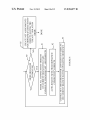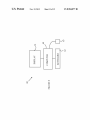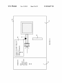
1
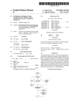
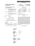
US008584077B1
(12) United States Patent
Kumar et a].
(54)
USER-CONTROLLABLE CONNECTIVITY
ENGINE FOR ELECTRONIC DESIGN
AUTOMATION TOOLS
(75) Inventors: Arbind Kumar, New Delhi (IN); John
Robert Lefebvre, II, Atlanta, GA (US);
Krishna Kumar Banka, Haryana (IN);
Peter Niday, Genoa, NV (US)
US 8,584,077 B1
(10) Patent N0.:
(45) Date of Patent:
Nov. 12, 2013
6,513,147 B1*
1/2003
6,857,110 B1*
2/2005 Rupp et a1.
Nakatsu et a1. ............. .. 716/120
7,016,794 B2*
3/2006
716/136
Schultz ......................... .. 702/64
7,353,482 B2
4/2008 Murakawa
7,707,495 B2*
4/2010
Hosotsubo .................. .. 715/243
8,046,730 B1
10/2011 Ferguson et al.
8,136,076 B2* 3/2012 Bachina et a1.
2009/0319975 A1*
2010/0100862
716/126
12/2009 Huynh et a1. ..
4/2010
Ohtsuka
2013/0125078 A1*
5/2013
Bosshart ..................... .. 716/126
(73) Assignee: Agilent Technologies, Inc., Santa Clara,
... ...
716/10
A1*
. . . ..
716/13
OTHER PUBLICATIONS
CA (US)
Notice:
Subject to any disclaimer, the term of this
patent is extended or adjusted under 35
U.S.C. 154(b) by 0 days.
Filed:
(51)
Int. Cl.
* cited by examiner
Jul. 30, 2012
G06F 17/50
(52)
Primary Examiner * Phallaka Kik
(57)
(2006.01)
US. Cl.
CPC ...... .. G06F 17/5077 (2013.01); G06F 17/5022
(2013.01); G06F17/505 (2013.01); G06F
17/5072 (2013.01); G06F 17/508] (2013.01)
USPC ......... .. 716/139; 716/102; 716/118; 716/126;
716/138; 703/14
(58)
Field of Classi?cation Search
CPC ............ .. G06F17/5022; G06F17/505; G06F
17/5072; G06F17/5077; G06F 17/5081
USPC
Microwave Of?ce Training, Feb. 15, 2008, Advancing the Wireless
Revolution, 15 pages.
(21) Appl. No.: 13/562,173
(22)
NioPluse User Manual Version 2.0.1 (Draft), Apr. 26, 2012,
NioPulse, 273 pages.
........... .. 716/139,102,118,126,138;703/14
See application ?le for complete search history.
ABSTRACT
A method for operating a computer system to generate a
layout of a device and a computer-readable medium contain
ing instructions that cause a computer system to carry out that
method are disclosed. The computer system has a display that
includes a display area. The computer system provides a list
of objects and creates user selected objects from the list for
inclusion in the display area. The computer assigns one of a
plurality of operating modes for each connectivity object in
the layout. The computer generates a Net assignment for each
connectivity object that is not forced to have a speci?c Net
assignment and for which automatic assignment of a Net is
allowed. The computer generated assignment depends on the
References Cited
operating mode associated with that connectivity object. The
U.S. PATENT DOCUMENTS
operating mode of at least one of the connectivity objects can
be altered by input from a user of said computer system.
(56)
5,414,809 A *
5/1995
Hogan et al. ................ .. 715/765
6,240,541 B1*
5/2001
Yasuda et al. ............... .. 716/112
20 Claims, 12 Drawing Sheets
[- 85
CREATE NET ASSIGNMENTS
FOR ORPHANED CONECTIVITY
MORE BRANCHES
TO PROCE S S?
OBJECTS HAVING THE
"CREATE" ISOLATION
MODE
1
MARK ALL CONNECTIVITY OBJECTS
ON CURRENT BRANCH THAT ARE
CAPABLE OF CHANGING NET ASSIGNMENTS
AUTO-REMOVE NETS FROM ORPHANED
CONNECTIVITY OBJECTS
V 81
V82
CHANGE NET ASSIGNMENTS FOR CONNECTIVITY OBJECTS
ON CURRENT BRANCH HAVING OPERATING MODES SET v83
DONE
US. Patent
NOV. 12, 2013
US 8,584,077 B1
Sheet 1 0f 12
<HEDGE
\ \\\m?\ \
OHEDGE
,~
\
\
\
\\
\
\
\
I
US. Patent
Nov. 12, 2013
Sheet 2 0f 12
US 8,584,077 B1
2AFIGURE
US. Patent
Nov. 12, 2013
Sheet 3 0f 12
US 8,584,077 B1
2BFIGURE
US. Patent
Nov. 12, 2013
Sheet 4 0f 12
US 8,584,077 B1
3FIGURE
US. Patent
Nov. 12, 2013
Sheet 5 0f 12
US 8,584,077 B1
4FIGURE
US. Patent
Nov. 12, 2013
Sheet 6 0f 12
US 8,584,077 B1
F5IGURE
US. Patent
Nov. 12, 2013
Sheet 7 0f 12
US 8,584,077 B1
6AFIGURE
U S. Patent
NOV. 12, 2013
Sheet 8 0f 12
US 8,584,077 B1
m5EDGE
HNUyMmEkZa
OZ
US. Patent
Nov. 12, 2013
Sheet 11 0f 12
US 8,584,077 B1
VQ
p61
DISPLAY
60
64
_/
COMPUTER KEYBOARD
9FIGURE
US. Patent
NOV. 12, 2013
Sheet 12 0f 12
US 8,584,077 B1
om
3
/.
H“MmU@2<h4Mm3HO
mZ"PWZ
mrUiO
2EDGE
QMUleanOw/H
I o .
mm
US 8,584,077 B1
1
2
USER-CONTROLLABLE CONNECTIVITY
ENGINE FOR ELECTRONIC DESIGN
AUTOMATION TOOLS
puter generated assignment depends on the operating mode
associated with that connectivity object. The operating mode
BACKGROUND
In one aspect of the invention, de?ning the plurality of
connectivity objects includes providing a list of objects in a
of at least one of the connectivity objects can be altered by
input from a user of said computer system.
user selectable format, including connectivity objects, that
Electronic design automation (EDA) tools are used to
may be placed in said display area and included in said layout;
facilitate the design and testing of complex electronic cir
cuitry. These systems provide tools for inputting both the
and selecting a connectivity object from the list based on user
input.
schematic drawing for a circuit and the layout of the actual
In one aspect of the invention, one of the modes prevents
the computer from automatically assigning a Net for one of
physical components on a semiconductor substrate or printed
circuit board. For example, a transmission line in the sche
the connectivity objects. In another aspect of the invention,
matic is represented in the layout by two physical conductors
one of the operating modes causes the computer system to
assign a Net to a ?rst connectivity object that is not on already
having de?ned widths and lengths that overlap one another on
two different layers in the layout. The designer can alter the
physical dimensions and placement of the components in the
layout view during the layout process. In addition, the sizes
and other parameters of the layout components can be opti
mized by the EDA tools during testing and optimization of the
circuit parameters.
on a Net to a Net determined by a Net assignment to a second
connectivity object that touches the ?rst connectivity object.
In a still further aspect of the present invention, one of the
operating modes causes the computer system to assign a Net
to a ?rst connectivity object on a ?rst Net that touches a
20
The schematic view and circuit layout view are typically
linked such that the components of the circuit in the layout
view remain connected during the editing of the layout view
in the layout tools. As the user moves objects in the layout
view, connectivity can be broken. Connectivity can also be
when the ?rst connectivity object is separated from a second
25
broken when the user moves components connected by a
trace in the layout view such that the conductor now includes
connectivity object and the ?rst and second connectivity
objects were assigned to the same Net. In another aspect of the
invention, one of the operating modes causes the computer
system to assign an orphaned connectivity object to a new
a break. The layout software attempts to maintain connectiv
ity in the layout view by providing constructs or actual wires
that are introduced to complete the connection that was bro
second connectivity object on a second Net that is different
from the ?rst Net based on the second Net. In another aspect
of the invention, one of the operating modes causes the com
puter system to re-assign a ?rst connectivity object a new Net
30
ken. In one system, the layout engine adds a physical wire to
unique Net when the connectivity object is created. In another
aspect of the present invention, one of the operating modes
causes the computer system to remove a Net assignment that
the layout that reconnects the two separated components.
is currently assigned to a connectivity object when it is
These wires can give rise to production errors if the wires are
orphaned.
not manually removed at the end of the layout process. In
another system, “Flight Wires” are introduced for this pur
pose. The Flight Wires are automatically removed when the
connection is restored.
Similarly, when two objects in the layout are moved such
that they overlap, an overlap region is formed that is indicated
by speci?c pattern on the display that is automatically
inserted by the layout engine. These overlaps signal that the
35
tivity object is created.
40
BRIEF DESCRIPTION OF THE DRAWINGS
objects need to be joined to form a single conductor. Again,
the generation of these constructs is not under the control of
FIGS. 1A-C illustrate the classes of objects.
the user.
In schematic driven modes of design, the software attempts
to maintain synchronization between the layout and the sche
matic. In complex layouts, the number of these constructs and
their locations can inhibit the designer’s ability to ef?ciently
input the design. In addition, the models used for maintaining
connectivity during the layout process vary depending on the
45
FIG. 2A illustrates a portion of a layout having a resistor
and a capacitor.
FIG. 2B illustrates the Nets included in the portion of the
layout shown in FIG. 2A.
50
particular EDA product, and hence, users of one system can
have dif?culty when they are forced to work in a different
FIG. 3 illustrates a Net Overlap Zone.
FIG. 4 shows a portion of FIG. 2A in which the user has
deleted trace 23 and moved Pin 27 such that it no longer is
connected to Pin 28.
FIG. 5 illustrates the removal of a Flight Wire by ?lling a
gap in the Net.
FIGS. 6A-6B illustrate the generation and removal of a Net
system.
SUMMARY
In another aspect of the invention, the operating mode
associated with one of said connectivity objects canbe altered
after the connectivity object has been created. In another
aspect of the invention the operating mode associated with
one of said connectivity objects is provided when the connec
55
Overlap Zone.
FIG. 7 is a ?ow chart of the procedure for identifying the
The present invention includes a method for operating a
computer system to generate a layout of a device and a com
puter-readable medium containing instructions that cause a
computer system to carry out that method. The computer
system has a display that includes a display area. A plurality
of connectivity objects are de?ned for the device, each con
Branches in the layout.
FIG. 8 illustrates the processing of each Branch.
FIG. 9 illustrates a computer system that is suitable for
60
practicing the present invention.
FIG. 10 illustrates the display that is used to input data that
de?nes the layout of a device.
nectivity object being part of the device. An operating mode is
de?ned for each connectivity object in the layout. The com
puter generates a Net assignment for each connectivity object
that is not forced to have a speci?c Net assignment and for
which automatic assignment of a Net is allowed. The com
DETAILED DESCRIPTION
65
At the layout level, a circuit can be viewed as a plurality of
objects that are connected together. In a layout design system
US 8,584,077 B1
3
4
according to the present invention, the user builds a layout by
selecting objects from a menu and placing instances of those
objects in the display area. The user can change the size and
shapes of the objects and connect the objects to provide the
layout of the ?nal device.
the process. Window 92 displays a menu of possible objects
that can be added to the display. In practice, the user indicates
an item from window 92 and drags that item onto the display
window 91. The user can modify the object by changing the
object shape, location, or other parameters particular to the
object in question. Shape 95 is an example of an orphaned
These objects can be viewed as belonging to ?ve classes.
connectivity object.
Refer to FIGS. 1A-C, which illustrate the classes of objects.
The ?rst class consists of shapes such as rectangles, circles,
The user can specify a particular object using a cursor 93
and predetermined operation such as double clicking a mouse
button associated with the cursor. A window 94 that provides
polygons, etc. that are layers of conductor as shown in FIG.
1A.
Referring to FIG. 1B, the second class consists of wires and
traces. Wire 11 has endpoints 12 and 13 that are connected by
the parameters associated with the object is then displayed. In
a line that has no thickness. Trace 1 6 differs from a wire in that
trace 16 has a thickness as well as end points 14 and 15.
window 94, and hence, change the parameters associated with
one aspect of the invention, the user can edit the data shown in
the corresponding object.
It should be noted that the display format shown in FIG. 10
is one exemplary display format. Other formats will be appar
ent from the following discussion. For example, the details of
the menu that specify the available objects can be varied to
Referring to FIG. 1C, the third class consists of compo
nents such as resistors, capacitors, inductors, microstrip lines,
transmission lines, etc. A component has two or more con
nection points and processes an input signal to produce an
output signal. A resistor is shown at 19 in FIG. 1C with its
connection points shown at 17 and 18.
make more ef?cient use of display space.
20
The fourth class consists of Pins. Pins are connection
points on objects such as the connection points on resistor 19
discussed above. A Pin can also be a separate object denoted
outputs that are different from the inputs, the terminals on a
component have different signals, and hence, are on different
Nets. Refer now to FIG. 2A, which illustrates a portion of a
by an arrow such as the arrow as discussed below. This type of
Pin provides a connection point to circuitry that is external to
the circuit in the layout.
The ?fth class of objects are “helper objects” such as text
25
advantages can be more easily understood in terms of a logi
cal construct referred to as a “Net”. The ?rst, second, and
fourth classes of obj ects are referred to as connectivity objects
layout having a resistor and a capacitor. Capacitor 21 is con
nected to resistor 22 by trace 23 which is connected to a Pin 25
on capacitor 21 and a Pin 26 on resistor 22. The other Pin on
resistor 22, Pin 28, is connected to a Pin 27 shown as an arrow.
Pin 27 connects the resistor to an external signal or power
labels, rulers, etc. Helper objects assist the designer while
creating a layout, and are not part of the manufactured circuit
or component. For example, a ruler will help the designer
place two components at a speci?ed spacing.
The manner in which the present invention provides its
Components are connected through various connectivity
objects. Since a component transforms inputs thereto into
30 source.
Refer now to FIG. 2B, which illustrates the Nets included
in the portion of the layout shown in FIG. 2A. Pin 25, trace 23,
and Pin 26 are on a ?rst Net 29. The objects that are on this Net
are indicated by the thicker boundary line in FIG. 2B. Pin 27
35
in the following discussion, as these objects have functions
analogous to wires in that they connect the other objects
and Pin 28 are on a second Net that is different from the ?rst
Net.
Two connectivity objects that overlap one another are said
connected thereto to the same signal. A number of connec
to be touching. The objects can be on the same layer or
tivity objects that are connected together to form a signal path
different layers that bind. Two layers are said to bind if the
layers can be interconnected electrically. For example, two
metal layers in a semiconductor can be connected by a via that
runs vertically between the metal layers.
A “Branch” is de?ned to be a group of connectivity objects
are referred to as a “Net”. A Net is analogous to a trace on a 40
printed circuit board and represents an electrical path in a
circuit. Any two points on a Net are shorted together electri
cally, and hence, have the same signal.
In the present invention, each connectivity object has a Net
assignment, with the possible exception of orphaned shapes
that are touching, but may be on different Nets. A “Net
45
Branch” is de?ned to be a group of connectivity objects which
discussed below. The assignment can be made automatically
by the present invention or forced by the user. When a change
are touching and are on the same Net. Referring to FIG. 2B,
Net 29 is a Net Branch. An example of a Branch in which the
is made to the layout, new Net assignments are made to re?ect
connectivity objects that are touching are on different Nets
will be discussed below.
Refer now to FIG. 3, which illustrates a Net Overlap Zone.
Here, Net 31, which includes trace 32 overlaps trace 23 which
is part of Net 29. In one aspect of the present invention, the
Net Overlap Zone is shown in the layout view if the connec
the change. For example, if a connectivity object is intro
duced into the layout that ?lls a gap between two objects that
are on different Nets, the Net assignments of the connectivity
objects on one of the previously de?ned Nets must be
changed to re?ect the new connectivity of the layout.
A connectivity object that is not touching any other con
nectivity object is referred to as an orphaned connectivity
50
tivity objects that are touching are not on the same Net. In this
55
object in the following discussion. A connectivity object can
start out in an orphaned state because it is placed on the layout
at a position such that it is not in contact with any other
In the present invention, Flight Wires show incomplete or
connectivity object. A connectivity object can become
orphaned when it is moved from a position in which it was
example, the Net Overlap Zone is shown at 34. The combi
nation of traces 23 and 32 is an example of a Branch in which
all the connectivity objects are not on the same Net.
60
“unrouted” Nets. A Flight Wire is de?ned to be a line that
appears in display area 91 and indicates a missing connection
touching another connectivity object to a position in which it
between two connectivity objects. A Net that has multiple Net
no longer touches other connectivity objects. Orphan shapes
Branches because all of its connectivity objects are not touch
ing is referred to as an unrouted Net. These connectivity
objects are on the same Net, but not physically connected.
The lack of connection can result from a connectivity object
do not have Net assignments when they are initially created.
Refer now to FIG. 10, which illustrates the display that is
used to input data that de?nes the layout of a device. Display
90 includes two windows 91 and 92. Window 91 displays the
current layout with the objects that have been de?ned so far in
65
being removed. The Flight Wires show the missing connec
tions by bridging the region that is not connected. Refer to
US 8,584,077 B1
5
6
FIG. 4. FIG. 4 shows a portion of FIG. 2A in which the user
has deleted trace 23 and moved Pin 27 such that it no longer
rate second Net, the ?rst Net is automatically merged with the
second Net by assignment of the connectivity objects on the
?rst Net to the second Net. If one of the connectivity objects
is not on a Net, that connectivity object is automatically
is connected to Pin 28. As a result, the remaining connectivity
objects of the Net, i.e., Pin 25 and Pin 26, are no longer
touching, and hence, Net 29 is now an unrouted Net. A Flight
Wire 37 is calculated and added to the layout view to indicate
a missing link. Similarly, a Flight Wire 38 is added to show the
missing connection between Pin 27 and Pin 28.
In the present invention, the user has two options for
removing a Flight Wire. First, the user can delete the Flight
placed on the same Net as the other connectivity object(s).
Therefore, “Join” can be viewed as a sub-set of “Merge”.
When two connectivity objects that have been merged are
touching, dragging them apart creates a Flight Wire.
In the “WYSIWYG” operating mode, when two connec
tivity objects, which are touching, are dragged apart, they
Wire by selecting the Flight Wire and pressing the delete key.
“Split”. In this case, each of the split objects is placed on a
The present invention then moves the connectivity objects
that were connected by the Flight Wire to different Nets, and
hence, the unrouted Net condition is removed and the Flight
Wire is no longer generated to signal an unrouted Net. The
unique Net. WYSIWYG can be viewed as a super-set with
operation of moving one of the Branches that was connected
by the Flight Wire to a new Net is referred to as splitting the
Net in the present invention. When the user splits the Net, the
connectivity objects when the touching objects are dragged
both “Merge” and “Split”, and neither creates a Flight Wire
nor a Net Overlap Zone.
In the “manual” operating mode, automatic changes to the
apart or when an object starts touching another are not per
formed. Dragging apart two connectivity objects on the same
Net creates a Flight Wire. Touching two connectivity objects
present invention assigns one of the two Branches to a new
Net. The identi?er for this Net is either provided automati
20
the new Net.
Second, the user can remove the Flight Wire by physically
that is suitable for practicing the present invention. The
connecting the Net Branches with one or more connectivity
objects such as traces or by moving one of the connectivity
objects so that the gap is ?lled. Refer now to FIG. 5, which
illustrates the removal of a Flight Wire by ?lling a gap in the
Net. In this example, Pin 27 is reconnected to Pin 28 by
inserting a trace 41 to ?ll the gap created by moving Pin 27.
25
When the gap is eliminated by ?lling the gap, the underlying
Net retains its identity, and the Flight Wires ?nally disappear
when the last connectivity object is inserted such that the
30
tains a database that includes a table specifying each connec
When the user creates a connectivity object, the connec
tivity object will be represented in a database in which space
35
ate” operating mode, the data processing system automati
nectivity object when that connectivity object is created by
40
Branch to a position that overlaps the other Branch. FIG. 6B
“None” mode, an orphaned connectivity object neither cre
ates nor eliminates a Net assignment associated with that
45
user would like to merge the two Nets into a single Net. In this
example, trace 32 is on Net Ni3, and trace 23 is on Net Ni5.
The user is given the choice of a name for the merged Net
from the names of the existing Nets. If the user chooses to
The Net Overlap Zone is then removed from the layout.
In one aspect of the invention, the behavior of the layout
mode when two connectivity objects are brought together or
the user. In the “Eliminate” operating mode, the orphaned
connectivity object is removed from the current Net during
the connectivity processing algorithm discussed below. In the
shows these Nets after the user has moved one of the Nets
such that the two Nets now overlap. In this case, a Net Overlap
merge the Nets, the unused Net name is eliminated, and the
selected Net de?nition is enlarged to include the connection
objects on the Net that was merged into the remaining Net.
is allocated for a Net identi?er for that object. In one aspect of
the invention, three isolation modes are provided. In the “Cre
cally assigns a unique Net identi?cation to an orphaned con
from one another. These are the two Nets shown in FIG. 3,
Zone 43 is automatically generated. If the user selects Net
Overlap Zone 43, a dialog box 44 appears, which asks if the
face for receiving input from a user. The user typically inputs
commands to the data processing system via a keyboard 62
and a pointing device 63. The data processing system main
tivity object in the layout and a Net identi?er for that object.
connectivity object touches both objects on the sides of the
prior to the Net Overlap Zone being created by moving one
present invention can be practiced on a data processing sys
tem 60 that includes computer 64, a graphical user interface
61 for displaying the layout drawing, and a data input inter
remaining gap.
The present invention also gives the user control of Net
Overlap Zones. Refer now to FIGS. 6A-6B, which illustrate
the generation and removal of a Net Overlap Zone. FIG. 6A
shows a portion of a layout having two Nets that are separate
on separate Nets creates a Net Overlap Zone. The user then
operates on the Flight Wire or Net Overlap Zones manually as
discussed above.
Refer now to FIG. 9, which illustrates a computer system
cally by the program or the user can provide an identi?er for
50
connectivity object. The user can also force a connectivity
object to be on a Net de?ned by the user.
The database also allocates space in the entry for each
object to store a “mode” for that object. The mode identi?es
one of the modes discussed above. The connectivity algo
rithm uses these modes to alter how the connectivity objects
are assigned to the Net after a change in the layout has
occurred. The database also allocates space for a Branch
identi?er for each connectivity object.
In one aspect of the invention, each time the layout
55
changes, the data processing system recalculates the Nets,
Flight Wires, and Net Overlap Zones that are to be displayed.
disconnected can be con?gured as an automatic mode or a
manual mode. In the automatic mode, three operations are
Refer now to FIG. 7, which is a ?ow chart of the procedure for
carried out without user intervention when two connectivity
identifying the Branches in the layout. At the beginning of the
objects start or stop touching. In the “Join” operating mode
process, all of the Branch indications are reset as shown at 71.
Next, a determination is made as to whether there is a con
when a connectivity object not on a Net touches another
nectivity objected with an unassigned Branch indicator as
shown at 72. If no connectivity object with an unassigned
Branch indicator is found, the process is complete. If a con
connectivity object on a Net, the system of the present inven
tion automatically puts the connectivity object that was not on
a Net on the existing Net. If both of the connectivity objects
are on separate Nets, touching them creates a Net Overlap
Zone.
In the “Merge” operating mode, when a connectivity object
on a ?rst Net touches another connectivity object on a sepa
65
nectivity object with an unassigned Branch indicator is found,
that connectivity object is assigned a Branch indicator that
has not yet been used for any connectivity object as shown at
73. Next all connectivity objects that touch that connectivity
US 8,584,077 B1
8
7
object either directly or through a connectivity object that has
In the fourth pass, Net assignments for connectivity objects
been assigned the Branch indicator are visited and given the
same Branch identi?er as shown at 74. The connectivity
that have the “WYSIWYG” operating mode set and have not
been visited in the preceding passes are made. For each unvis
objects in the database are then searched for a connectivity
object without a Branch indicator. When no connectivity
which is either on a forced, or an implicitly forced Net, mark
ited connectivity object with the WYSIWYG operating mode
the connectivity object as visited. Visit all connectivity
objects that are touching this connectivity object either
object with an unassigned Branch ?eld is left, all of the
Branches are de?ned.
The algorithm then proceeds to process each Branch. Refer
directly or indirectly through another connectivity object and
now to FIG. 8, which illustrates the processing of each
Branch. In the ?rst step, all connectivity objects on the current
Branch that have Net assignments that can be changed are
marked as shown at 81. First, all connectivity objects on the
that can change their Net assignments. Put these connectivity
Branch are marked as being “unvisited”. Next, the connec
ti?ers for Nets that lost connectivity objects in this procedure
tivity objects on the Branch that are capable of changing their
Net assignments are marked. This will be all connectivity
objects on the Branch except connectivity objects which are
are recorded. If one or more Nets are eliminated in this pro
objects on the same Net as the identi?ed connectivity object,
and mark these connectivity objects as being incapable of
changing their Nets. In one aspect of the invention, the iden
cess, the eliminated Net names are placed in a recycle pool so
that the same net names can be reused when required.
When all of the Branches have been processed as shown at
already on a Net forced by the user or on an implicitly forced
80, Nets are created for orphaned connectivity objects having
Net by virtue of being on the “Join” operating mode.
the “Create” isolation mode set as shown at 85. The computer
Next, the Net assignments from orphaned connectivity
objects that can be removed from a Net are removed as shown 20 goes through the list of connectivity objects to ?nd any
remaining connectivity objects with the “Create” isolation
at 82. A connectivity object is not removed from a Net if either
the Branch has a forced Net, or any of the connectivity objects
mode set and that are not on a Net. For each such connectivity
on the Branch is not marked with the “Eliminate” isolation
object, a new Net is created. Then any connectivity objects
mode discussed above. If a connectivity object is removed
from a Net, the Net is deleted if the Net is empty and the
Branch processing is ?nished for this step.
that can still have their Nets changed and which are connected
25
Next, the Branch connectivity is updated for connectivity
The above-described embodiments of the present inven
tion have been layout driven. That is, the user enters the layout
without reference to a schematic that has already been entered
objects having their operating mode set as shown at 83. This
is a four pass procedure. In the ?rst pass, connectivity objects
that are touching but cannot change their Nets are identi?ed as
shown at 83. The connectivity objects are processed one at a
30
into the design system and which de?nes the connectivity
between the various components of the device being
designed. A schematic diagram can then be created from the
completed layout view of the device.
35
matic driven system. In this case, Flight Wires are generated
time to reset the unvisited marking for connectivity objects
that are either on a forced Net or an implicitly forced Net.
When a such a connectivity object is found, the connectivity
object is marked as visited. Then all connectivity objects on
the same Net that touch the connectivity object in question
either directly or through another connectivity object on the
Net are marked as being incapable of having their Net assign
ment changed. Finally, all connectivity objects on the Branch
are again reset to the “unvisited” state.
However, the present invention can be utilized in a sche
when a Net de?ned on the schematic is broken either because
it has not been fully inputted in the layout mode by connecting
all the connectivity objects corresponding to that Net or
because components in the layout mode have been moved or
40
In the second pass, Net assignments to connectivity objects
change their Net assignments are assigned new Net assign
45
plished by ?nding each connectivity object that is marked
forced, Net. For each such identi?ed connectivity object, the
connectivity object is marked as being visited. For each con
101 . Examples of such media are non-transient media such as
50
which can change its Net assignment, put that connectivity
object on the same Net as the identi?ed connectivity object
and mark that connectivity object as being incapable of
changing its Net assignment.
In the third pass, Net assignments for connectivity objects
55
that have the “Merge” operating mode set and have not been
“visited” in the preceding passes are made. For each unvisited
60
connectivity object as visited. Visit all connectivity objects
that are touching this connectivity object either directly or
indirectly through another connectivity object and that can
change their Net assignments. Put these connectivity objects
on the same Net as the identi?ed connectivity object, and
mark these connectivity objects as being incapable of chang
ing their Nets.
memory devices.
The above-described embodiments of the present inven
tion have been provided to illustrate various aspects of the
invention. However, it is to be understood that different
aspects of the present invention that are shown in different
speci?c embodiments can be combined to provide other
embodiments of the present invention. In addition, various
modi?cations to the present invention will become apparent
from the foregoing description and accompanying drawings.
connectivity object with the “Merge” operating mode which
is either on a forced, or an implicitly forced Net, mark the
medium that causes a computer to execute instructions that
carry out the above-described method for operating a com
puter system. For the purposes of this application, the term
“computer-readable medium” is de?ned to be any medium
that constitutes patentable subject matter under 35 U.S.C.
unvisited and which is either on a forced, or an implicitly
nectivity object that touches the identi?ed connectivity object
either directly or through another connectivity object, and
eliminated. In the schematic driven embodiments, one or
more of the connectivity objects are forced onto Nets that are
de?ned in the schematic.
The present invention includes any computer readable
which are touching directly, or indirectly, and which can
ments if they are connected to a connectivity object that
cannot have its Net assignment changed. This is accom
directly or indirectly to the connectivity object in question are
assigned to the new Net.
Accordingly, the present invention is to be limited solely by
the scope of the following claims.
What is claimed is:
1. A method of operating a computer system having a
display area to provide a layout for an electronic device, said
65
method comprising:
de?ning a plurality of connectivity objects within said
computer system, each connectivity object being part of
said electronic device;
US 8,584,077 B1
10
12. A computer-readable medium that includes instruc
receiving one of a plurality of operating modes for each
connectivity object in said layout, said operating mode
tions that cause a computer having a display area to generate
a layout of a device by:
determining how a Net is automatically assigned to that
connectivity object, said operating mode of at least one
de?ning a plurality of connectivity objects, each connec
tivity object being part of said device;
of said connectivity objects being alterable by input
receiving one of a plurality of operating modes for each
from a user of said computer system; and
for each connectivity object that is not forced to have a
connectivity object in said layout, said operating mode
determining how a Net is automatically assigned to that
connectivity object, said operating mode of at least one
speci?c Net assignment and for which automatic assign
ment of a Net is allowed by said operating mode received
of said connectivity objects being alterable by input
for that connectivity object, causing said computer sys
from a user of said computer system; and
for each connectivity object that is not forced to have a
tem to make a Net assignment for that connectivity
object based on said operating modes and Nets assigned
speci?c Net assignment and for which automatic assign
to other connectivity objects that are connected to that
ment of a Net is allowed by said operating mode received
connectivity object.
for that connectivity object, assigning a Net assignment
for that connectivity object based on said operating
modes and Nets assigned to other connectivity objects
2. The method of claim 1 wherein de?ning said plurality of
connectivity objects comprises:
providing a list of objects in a user selectable format,
that are connected to that connectivity object.
13. The computer-readable medium of claim 12 wherein
including connectivity objects, that are placed in said
display area and included in said layout; and
selecting a connectivity object from said list of objects
20
providing a list of objects in a user selectable format,
based on user input.
including connectivity objects, that are placed in said
3. The method of claim 1 wherein one of said operating
display area and included in said layout; and
modes prevents said computer from automatically assigning
a Net for that connectivity object.
4. The method of claim 1 wherein one of said operating
selecting a connectivity object from said list of objects
25
automatically assigning a Net for that connectivity object.
determined by a Net assignment to a second connectivity
15. The computer-readable medium of claim 12 wherein
object that touches said ?rst connectivity object.
30
Net Overlap Zone if said ?rst and second connectivity objects
are assigned different Nets.
6. The method of claim 1 wherein one of said operating
modes causes said computer system to assign a Net to a ?rst
connectivity object on a ?rst Net that touches a second con
35
Net based on said second Net.
7. The method of claim 1 wherein one of said operating
modes causes said computer system to re-assign a ?rst con
Net.
8. The method of claim 1 wherein one of said operating
modes causes said computer system to assign an orphaned
connectivity object to a new unique Net when said connec
40
one of said operating modes causes said computer system to
assign a Net to a ?rst connectivity object on a ?rst Net that
touches a second connectivity object on a second Net that is
different from said ?rst Net based on said second Net.
18. The computer-readable medium of claim 12 wherein
45
connectivity object is separated from a second connectivity
object and said ?rst and second connectivity objects were
assigned to the same Net.
19. The computer-readable medium of claim 12 wherein
9. The method of claim 1 wherein one of said operating
one of said operating modes causes said computer system to
modes causes said computer system to remove a Net assign
50
assign an orphaned connectivity object to a new unique Net
when said connectivity object is created.
objects when that connectivity object is orphaned.
20. The computer-readable medium of claim 12 wherein
10. The method of claim 1 wherein said operating mode
associated with one of said connectivity objects is altered
one of said operating modes causes said computer system to
remove a Net assignment that is currently assigned to one of
after said connectivity object has been created.
11. The method of claim 1 wherein said operating mode
associated with one of said connectivity objects is provided
when said connectivity object is created.
16. The computer-readable medium of claim 15 wherein
said computer displays a Net Overlap Zone if said ?rst and
second connectivity objects are assigned different Nets.
17. The computer-readable medium of claim 12 wherein
one of said operating modes causes said computer system to
re-assign a ?rst connectivity object a new Net when said ?rst
tivity object is created.
ment that is currently assigned to one of said connectivity
one of said operating modes causes said computer system to
assign a Net to a ?rst connectivity object that is not already on
a Net to a Net determined by a Net assignment to a second
connectivity object that touches said ?rst connectivity object.
nectivity object on a second Net that is different from said ?rst
nectivity object a new Net when said ?rst connectivity object
is separated from a second connectivity object and said ?rst
and second connectivity objects were assigned to the same
based on user input.
14. The computer-readable medium of claim 12 wherein
one of said operating modes prevents said computer from
modes causes said computer system to assign a Net to a ?rst
connectivity object that is not on already on a Net to a Net
5. The method of claim 4 wherein said computer displays a
de?ning said plurality of connectivity objects comprises:
55
said connectivity objects when that connectivity object is
orphaned.
UNITED STATES PATENT AND TRADEMARK OFFICE
CERTIFICATE OF CORRECTION
PATENT No.
: 8,584,077 B1
APPLICATION NO.
: 13/562173
: November 12, 2013
: Arbind Kumar et a1.
DATED
INVENTOR(S)
Page 1 of 1
It is certified that error appears in the above-identi?ed patent and that said Letters Patent is hereby corrected as shown below:
On Title page, Item (56), under “Other Publications”, in column 2, line 1, delete “NioPluse” and insert
--NioPulse--, therefor.
Signed and Sealed this
Twenty-?fth Day of February, 2014
WMZ44L_
Michelle K. Lee
Deputy Director 0fthe United States Patent and Trademark O?ice