1
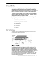
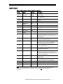
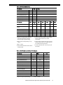
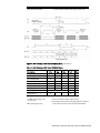
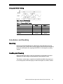
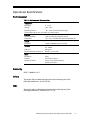
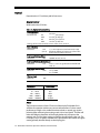
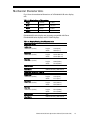
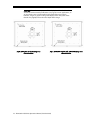
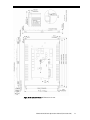
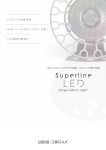
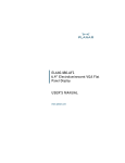
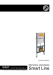
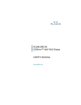
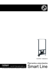
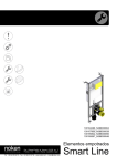
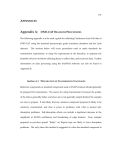
EL640.480-A SB Series 640 x 480 Pixel, True Gray Scale Displays USER’S MANUAL www.planar.com Revision Control Date Description August 1999 Document number PI01114 Ver 12 June 2004 Document number 020-0358-00A Contents Product Profile ............................................................................................................................................................3 EL Technology.............................................................................................................................................................3 Electrical Characteristics..........................................................................................................................................4 Connector Layout .................................................................................................................................................4 Signal Inputs ...........................................................................................................................................................5 Power and control Inputs...................................................................................................................................6 Control Basics .........................................................................................................................................................6 Power Input.............................................................................................................................................................6 Connectors ..............................................................................................................................................................6 Programmable features......................................................................................................................................7 Input Specifications..............................................................................................................................................7 Display Features .........................................................................................................................................................8 Video Data ...............................................................................................................................................................8 Gray Shades.............................................................................................................................................................8 Self Test.....................................................................................................................................................................9 Display Enable........................................................................................................................................................9 Brightness Control ................................................................................................................................................9 Low Power Mode ..................................................................................................................................................9 Two Data Parallel Mode ......................................................................................................................................9 EMC ............................................................................................................................................................................9 Display Operation Modes .....................................................................................................................................10 Timing Compatibility with Planar Displays................................................................................................11 Display Operation Modes.................................................................................................................................12 Setup and Hold Timing .....................................................................................................................................15 Installation and Handling......................................................................................................................................15 Mounting ...............................................................................................................................................................15 Handling and Cleaning .....................................................................................................................................15 Video Signal Input...............................................................................................................................................16 Avoiding Burn-in .................................................................................................................................................16 Operational Specifications ...................................................................................................................................17 Environmental......................................................................................................................................................17 Reliability................................................................................................................................................................17 Safety.......................................................................................................................................................................17 EMC ..........................................................................................................................................................................17 Optical.....................................................................................................................................................................18 Display Colour .................................................................................................................................................18 Filter ....................................................................................................................................................................18 Mechanical Characteristics...................................................................................................................................19 Description of Warranty ........................................................................................................................................22 Easy to Use .................................................................................................................................................................22 Support and Service................................................................................................................................................23 Ordering Information .............................................................................................................................................23 Figures Figure 1. EL Technology......................................................................................................................................3 Figure 2. Connector Layout ...............................................................................................................................4 Figure 3. VGA Modes..........................................................................................................................................12 Figure 4. 640 Columns x 480 Rows Norrmal Mode .................................................................................14 Figure 5. Setup and Hold Timing...................................................................................................................15 Figure 6. EL640.480-A3 SB Viewing Area Characteristics......................................................................20 Figure 7. EL640.480-A4 SB and -AD4 SB Viewing Area Characteristics............................................20 Figure 8. EL640.480-A SB, Back and Side Views........................................................................................21 Tables Table 1. Signal Inputs: J1 (Video Interface Connector) ............................................................................5 Table 2. Power and Control Inputs .................................................................................................................6 Table 3. Connectors..............................................................................................................................................6 Table 4. Input Specifications .............................................................................................................................7 Table 5. Levels of Gray.........................................................................................................................................8 Table 6. Display Operation Modes ................................................................................................................11 Table 7. 350 Row VGA Modes .........................................................................................................................12 Table 8. 400 Row VGA Modes .........................................................................................................................13 Table 9. 640 Columns x 480 Row VGA Modes...........................................................................................13 Table 10. 640 Columns x 480 Rows Norrmal Mode.................................................................................14 Table 11. Setup and Hold Timing ..................................................................................................................15 Table 12. Environmental Characteristics ....................................................................................................17 Table 13. Optical Characteristics....................................................................................................................18 Table 14. Display External Dimensions........................................................................................................19 Table 15. Display Viewing Area Characteristics........................................................................................19 Product Profile The EL640.480-A SB series displays are VGA compatible high-resolution electroluminescent (TFEL) flat panel displays. They replace the bulky CRT in control and instrument product designs. They feature an integrated DC/DC converter, and their compact dimensions save space that can allow addition of features or reduction in overall size. The displays are mechanically identical. The display format of EL640.480-A SB series displays is VGA compatible (640 columns by 480 rows) with sixteen true shades of gray. The display supports and automatically detects all standard VGA modes. The displays require a single +12Vdc power source and five basic types of input signals to operate : 1. Video Data or pixel information 2. Video Clock, pixel clock, or dot clock 3. Horizontal Sync 4. Vertical Sync 5. Blanking EL Technology The display consists of an electroluminescent glass panel and a mounted circuit board with addressing electronics. Figure 1. EL Technology. The EL glass panel is a solid-state device with a thin film luminescent layer sandwiched between transparent dielectric layers and a matrix of row and column electrodes. The row electrodes, in back, are aluminium; the column electrodes, in front, are transparent. The entire thin film device is deposited on a single glass substrate. The glass panel is mounted with an elastic spacer to an assembly support carrying the electronic circuit assembly board (ECA) mounted on the support. The driver electronics is connected to the EL glass panel with soldered lead frame interconnects. The result is a flat, compact, reliable and rugged display device. EL640.480-A SB Series Operations Manual (020-0358-00A) 3 The EL640.480-AD4 SB display includes a dark ICE (Integrated Contrast Enhancement) background in the display glass. ICE background significantly improves the luminance contrast of the display in bright ambients. ICE also removes the halo around the lit pixels in dark ambient making the appearance of each pixel crisp and clear. The 640 column electrodes and 480 row electrodes are arranged in an X-Y formation with the intersecting areas performing as pixels. Voltage is applied to both the correct row electrode and the correct column electrode to cause a lit pixel. Operating voltages required are provided by an integrated DC/DC converter. Electrical Characteristics Connector Layout Fig 2. The input connectors and programmable jumpers with their factory settings. 4 EL640.480-A SB Series Operations Manual (020-0358-00A) Signal Inputs Table1. Signal Inputs: J1 (Video Interface Connector). Pin No Signal Symbol Description 1, 3, 5, 15 17, 19, 21 2 Ground Video data (LSB) GND D0 4 Video data D1 Signal return Primary video data. In two data parallel mode even video data (see note below and "Two-Data-Parallel" on page 9). 6 8 Video data Video data (MSB) Video data (LSB) Video data D2 D3 D6 D7 18 Video data Video data (MSB) Video Clock 20 Blanking _BLANK 22 Horizontal Sync HS 24 Vertical Sync VS 26 Self test SELFTST If high or left disconnected, self test is performed (see page 8). 27 Colour map COLMAP 28 Enable ENABLE 30 Low power _LOWPOW 29, 33, 34 7, 9, 11, 13 23, 25, 31, 32 Reserved Not used Not used N/C N/C If high, data bits are interpreted as colours (see page 8). If low, data bits are interpreted as binary data. If left disconnected, interpretation depends on MAP jumper. Display operation is enabled when high or left disconnected If low, display brightness and contrast is reduced for lower power consumption. These pins are reserved for future use Not connected Not connected 10 12 14 16 D4 D5 VCLK Odd video data used in two data parallel mode (see note below and “Two-Data-Parallel” on page 9). Synchronizing signal for data lines, HS, VS and _BLANK. Data inputs are read at the rising edge of VCLK. Used in VGA modes. In NORMAL mode should be high or left disconnected. The horizontal sync signal HS controls the internal row counter and in the NORMAL mode the horizontal position of the picture. The vertical sync signal VS controls the vertical position of the picture. Note: Two data parallel mode is selected when DCON '2-d' bridge is open. On default setting the bridge is set and 4 bits wide data is input to D0...D3 and does NOT require D4...D7 to be connected. EL640.480-A SB Series Operations Manual (020-0358-00A) 5 Power and Control Inputs Table 2. Power and Control Inputs Pin Signal Symbol Description J2 (Power input connector) 1 Voltage Vcc2 2 3 4 Ground Ground Reserved GND GND Supply voltage (+12 Vdc) converted to required internal voltages Power return Power return (same as pin 2) Reserved for compatibility with Vcc1 input in other Planar displays. Do not use. J3 (Luminance control input) 1 Luminance control LUMPOT1 2 Luminance control LUMPOT2 The inputs for an external 50 kΩ log potentiometer to adjust the luminance of the display. If left disconnected, the luminance is at the max level. See page 9 for details. Control Basics The EL panel is a matrix structure, with column and row electrodes arranged in X-Y formation. Light is emitted when an AC voltage of sufficient amplitude is applied at a row-column intersection. The display operation is based on the symmetric, line at a time data addressing scheme. Input thresholds to the display are 74ACT CMOS compatible (TTL thresholds). Power Input The only required supply voltage for the display is +12Vdc (Vcc2). All internal high voltages are generated from Vcc2. Connectors Table 3. Connectors. 6 J1 34-pin header Mating Locking clip ODU 511.266.003.034 or eq. ODU 517.065.003.034 or eq. ODU 511.065.734.700 or eq. J2 4-pin header Mating Protector Hirose DF1–4P–2.5 DS or eq. Hirose DF1–4S–2.5 R 24 Hirose DF1–4A 1.33 J3 2-pin header Mating Protector Hirose DF1–2P–2.5 DS or eq. Hirose DF1–2S–2.5 R 24 Hirose DF1–2A 1.33 EL640.480-A SB Series Operations Manual (020-0358-00A) Programmable Features Two data parallel input mode is selected when bridge DCON on the ECA is open (see fig. 2). In default configuration the DCON bridge is set. See page 9 for more details. The method of gray scale coding can be selected either with COLMAP control input (J1/27) (see Signal Inputs on page 5) or with solderable bridge MAP on the ECA (see fig. 2). If COLMAP is left disconnected, MAP brigde defines the mode. If MAP is left open (default), colour mapping is selected. If MAP is bridged, binary coding is the method. Note that if COLMAP control input is used MAP has to be open. See page 8 for more details on colour mapping. Notice: Only binary coding of input data can be used with Two Data Parallel mode. See Gray Shades and Two Data Parallel Mode in page 9. For compatibility to previous versions of A series displays the horizontal and vertical positioning of the image can be adjusted with solderable bridges on the ECA of the display. VERPOS0–VERPOS2 (MSB) are for vertical positioning and HORPOS0–HORPOS3 (MSB) are for horizontal positioning (see Fig. 2). Both settings form a binary number where a set bridge is a "0" and open bridge a "1". The adjustment range for VERPOS is 0 to 7 upwards (default 000 for no shift) and HORPOS 7 right (0000) to 8 left (1111) (default 0111 for no shift). Notice: Due to the fact that picture positioning is not supported by Planar multi-colour VGA displays and may not be supported by some future Planar VGA displays, the use of this feature should be avoided. Input Specifications Table 4. Input Specifications. Parameter Symbol Logic input HIGH Logic input LOW Supply voltage Supply current at 12V Supply current at 12V LowPow Vcc1 Icc1 Icc2 Min. Typ. Max. Absolute min./max. 2V — — Vcc1 0.8 V +5.5 V abs. max. -0.5 V abs. min. 11.4 V — — 12 V 1.3 A 0.9 A 13.2 V 2.6 A 1.5 A 15 V abs. max. Operating conditions: Ambient temperature 25°C Note: Absolute maximum ratings are those values beyond which damage to the device may occur. The minimum and maximum specifications in this Operations Manual should be met, without exception, to ensure the longterm reliability of the display. Planar does not recommend operation of the display outside these specifications. EL640.480-A SB Series Operations Manual (020-0358-00A) 7 Display Features The EL640.480-A SB series displays are timing and pin compatible with the feature connector on VGA display controller cards. Pins 1–26 on the feature connector connect directly to corresponding pins on data input connector J1 of the display. Pins 27–34 may be left disconnected. Video Data Input signals D0, D1, D2, D3 (and D4, D5, D6, D7 in two data parallel mode) contain the four bit serial video data to be displayed on the screen. Pixel information is supplied from left to right and from top to bottom. The four data bits can be interpreted as colour data or binary gray shade codes. Gray Shades The display is capable of displaying sixteen true levels of luminance. The four bit video input data can either be mapped to colour coding or binary gray shade coding. Colour coding is selected by pulling COLMAP control input HIGH. A LOW state in COLMAP control input selects binary coding. See 'Programmable Features' in page3 for setting the coding if COLMAP input is left disconnected. Table 5. 16 levels of gray when colour mapping is used. D3 D2 D1 D0 Colour Gray Level 0 0 0 0 0 0 0 0 1 1 1 1 1 1 1 1 0 0 0 0 1 1 1 1 0 0 0 0 1 1 1 1 0 0 1 1 0 0 1 1 0 0 1 1 0 0 1 1 0 1 0 1 0 1 0 1 0 1 0 1 0 1 0 1 Black Blue Green Cyan Red Magenta Brown White Gray Lt. Blue Lt. Green Lt. Cyan Lt. Red Lt. Magenta Yellow White(High Int) 0 1 5 8 2 3 6 11 4 7 12 13 9 10 14 15 For maximum text readability, the default text brightness level is mapped in text modes 2+, 3+, 7 and 7+ to high intensity white (level 15). If colour coding is selected levels 11 and 15 are changed. If binary coding is selected, levels 7 and 15 are changed respectively. Please find complete description of VGA modes in page 11. 8 EL640.480-A SB Series Operations Manual (020-0358-00A) Self Test The operation of the display can be tested using the SELFTST control input (J1/26). Self test is performed if SELFTST is HIGH or left disconnected. By applying power to the display without any other input, the display starts scanning, displaying all pixels with full brightness except a pattern of unlit pixels in the center of the topmost row. Display Enable The operation of the display can be shut off for screen save or minimal power consumption by a LOW state on ENABLE control input (J1/28). When disabled power consumption of the display drops to appr. 2 W. In normal operation ENABLE input should be pulled HIGH or left disconnected (internal pull-up) Brightness Control The brightness of the display can be adjusted from below 20% up to full brightness by a 50kΩ external logarithmic potentiometer between LUMPOT1 and LUMPOT2 control inputs (J3/1 and /2 respectively). The control function is achieved by sinking a small (<0.5 mA typ.) current from LUMPOT1 to LUMPOT2 (When open, the voltages are at 5 V and 0 V respectively). If the two inputs are left disconnected, the brightness is at its maximum level. Low Power Mode The Low Power function reduces power consumption of the display to typically 11 W. The function reduces slightly the contrast and average brightness of the display. The function is selected by LOW state in _LOWPOW control input (J1/30). If the input is pulled HIGH or left disconnected, normal operation is selected. Two Data Parallel Mode For compatibility with flat panel controllers, it is possible to input the data of two pixels simultaneously by using the secondary data input lines D4–D7. This mode is selected when solderable bridge DCON is open. In default configuration bridge DCON is set. Notice: Only binary coding of input data can be used with Two Data Parallel mode. See Gray Shades. EMC The conductive metal assembly support between the display glass and the electronics as well as the metal back cover act as a ground plane for EMI signals. In conjunction with data input connector J1, there is a connection lug from assembly support through the ECA. This lug can be used to ground the shield of the signal input cable. Note that the assembly support is also connected to the signal ground of the display (GND in J1). For best EMC performance, the four display mounting ears should be tied to customer chassis ground. Care should be taken to avoid loops in system grounding. EL640.480-A SB Series Operations Manual (020-0358-00A) 9 The EMC of the end product can be additionally improved using the four layer board version of the display. One of the additional layers of this version is dedicated to signal ground. It provides an efficient ground path for high frequency interferences present in the system. See Ordering Information on page 23. For more details on improving the EMC of the end product please contact Planar. Display Operation Modes The display supports all standard VGA display modes. It also supports the NORMAL mode which is similar to that used by most other Planar products. Mode selection is automatically performed by the display detecting the state of _BLANK at rising edge of VS and the polarities of the VS and HS input signals at the rising edge of the _BLANK signal. See timing diagrams on pages 12-14 for more details. VGA Modes: In VGA modes _BLANK signal is used to frame the valid video data. The number of active pixels in each VGA mode is determined by calculating the number of VCLK pulses during the HS LOW time (T8 on timing diagrams). The 320 column modes are detected additionally by the amount of VCLK pulses during the front porch (T7 on VGA mode timing diagrams). In 320 and 360 column VGA modes each pixel data is displayed in two successive pixels. In 720 and 360 column VGA text modes the data of every ninth pixel is omitted to be able to display the whole data line with 640 pixels. There is no data loss due to blank data in the ninth column of the text box. The border timing included in _BLANK is taken into account in the interpretation of this signal and the video data during vertical borders is displayed in 350 and 400 line modes but ignored in 480 line modes. See details on setup and hold timing on page 15 and the timing of different VGA modes on page 12-13. Normal Mode: In this mode only seven input signals are needed: video data (D0, D1, D2 and D3), video clock (VCLK), horizontal sync (HS) and vertical sync (VS). _BLANK is not used and should be pulled HIGH or left disconnected. In Normal Mode the last 640 pixels before the fall of the HS are displayed. The topmost row displayed is the first HS HIGH time ending after HS Hold from VS time (T3 in Normal Mode page 14) from the rising edge of the VS. See details on setup and hold timing on page 15 and Normal Mode timing on page 14. Timing Compatibility with Planar displays The VGA mode detection of EL640.480-A SB series displays is compatible with Planar EL640.480-AM series displays and EL7768MS display and is downwards compatible with Planar EL640.400-C and -CB series displays (350 line and 400 line modes). 10 EL640.480-A SB Series Operations Manual (020-0358-00A) Display Operation Modes Table 6. Display Operation Modes. VGA Mode Type Text format Char. box Vsync Freq. (Hz) Pixels (software) Double Scan Hor/Ver Border 0, 1 2, 3 0*, 1* 2*, 3* 0+, 1+ 2+, 3+ 4, 5 6 7 7+ D E F 10 11 12 13 NORMAL text text text text text text graphics graphics text text graphics graphics graphics graphics graphics graphics graphics graphics 40 x 25 80 x 25 40 x 25 80 x 25 40 x 25 80 x 25 40 x 25 80 x 25 80 x 25 80 x 25 40 x 25 80 x 25 80 x 25 80 x 25 80 x 30 80 x 30 40 x 25 8x8 8x8 8 x 14 8 x 14 9 x 16 9 x 16 8x8 8x8 9 x 14 9 x 16 8x8 8x8 8 x 14 8 x 14 8 x 16 8 x 16 8x8 70 70 70 70 70 70 70 70 70 70 70 70 70 70 60 60 70 65 max 320 x 200 640 x 200 320 x 350 640 x 350 360 x 400 720 x 400 320 x 200 640 x 200 720 x 350 720 x 400 320 x 200 640 x 200 640 x 350 640 x 350 640 x 480 640 x 480 320 x 200 640 x 480 Yes Yes No No No No Yes Yes No No Yes Yes No No No No Yes No L 8/7 R 8/7 L 8/6 R 8/6 L 9/7 R 9/7 L 8/7 R 8/7 R 9/6 R 9/7 L 8/7 R 8/7 R8/6 R8/6 R 8/T 8 R 8/T 8 L 4/7 NOTES: 1. In VGA-modes 0+, 1+, 2+, 3+, 7 and 7+ the box size is narrowed to 8 pixels wide by omitting every 9th pixel. 2. In VGA-modes 0, 1, 2, 3, 4, 5, 6, D, E and 13 rows are automatically double scanned by the VGA card. 3. The border values used to fit the image to the fixed matrix size is marked by letters R=right border, L=left border, T=top border. 4. To improve text brightness, the gray level of the default text foreground colour is changed to level 15 in VGA-text modes 2+, 3+, 7 and 7+. If colour mapping is selected gray levels 11 and 15 are changed, and if binary coding is selected, levels 7 15 are changed. EL640.480-A SB Series Operations Manual (020-0358-00A) 11 Figure 3. VGA Mode Table 7. 350 Row VGA Modes. Description T1 Vertical Border T2 Vertical Front Porch T3 VS Pulse Width T4 Vertical Back Porch T5 Vertical Border HS pulses / VS VS frequency Description T6 Horizontal Border T7 Horizontal Front Porch T8 HS Pulse Width T9 Horizontal Back Porch T10 Horizontal Border VCLK pulses / HS HS period 1. Borders are displayed but otherwise ignored by the display controller, value is for typical system timing. Unit Note tHS tHS tHS tHS tHS 1 2 3 6 31/32 2 53/54 6 449 70 1 Hz 320 640 720 Unit Note 8 1-7 32-51 12 8 400 31.8 8 8/11 64-103 37/40 8 800 31.8 9 9 104-111 45 9 900 31.8 tVCLK tVCLK tVCLK tVCLK tVCLK 4 5 6 µs 5. Used for 320 column mode sensing. Typical value there is 4. 2. Min. 2 HS-pulses + (130-T1-T4-T5 [in tHS]) x 3 µs + 60 µs. 6. Used for column mode sensing. Typical values are 48, 96 and 108 for 320, 640 and 720 column modes respectively. 3. Min. 1 x tVCLK. 7. Size of removed border in 320 mode. 4. Ignored in 320 column mode. 12 EL640.480-A SB Series Operations Manual (020-0358-00A) 7 Table 8. 400 Row VGA Modes. Description Unit Note 1 2 3 T1 Vertical Border T2 Vertical Front Porch T3 VS Pulse Width T4 Vertical Back Porch T5 Vertical Border HS pulses / VS VS frequency 7 6 2 27 7 449 70 tHS tHS tHS tHS tHS Description 320 320(13 ) 360 640 720 Unit Note 8 4 9 8 9 tVCLK 4 1-3 5-7 4 8/11 9/13 tVCLK 5 32-51 13 8 400 31.8 32-51 18 4 400 52-60 14 9 450 31.8 64-103 37/40 8 800 31.8 104-111 40/45 9 900 31.8 tVCLK tVCLK tVCLK 6 T6 Horizontal Border T7 Horizontal Front Porch T8 HS Pulse Width T9 Horizontal Back Porch T10 Horizontal Border VCLK pulses / HS HS period 1 Hz µs 1. Borders are displayed but otherwise ignored by the display controller, value is for typical system timing. 5. Used to detect 320,320(13) and 360 column modes. Typical values are 3, 6 and 4 respectively. 2. Min. (80-T1-T3-T4-T5 [in tHS]) x 3.3 µs + 50 µs. 6. Used to detect column mode. Typical values are 48, 96 and 108 for 320, 320(13), 640 and 720 column modes respectively. 3. Min. 1 x tVCLK. 4. Size of removed border in 640 and 720 column modes. 7. Size of removed border in 320, 320(13) and 360 modes. Table 9. 640 Columns x 480 Rows VGA Modes. Description Unit T1 Vertical Border T2 Vertical Front Porch T3 VS Pulse Width T4 Vertical Back Porch T5 Vertical Border HS pulses / VS VS frequency T6 Horizontal Border T7 Horizontal Front Porch T8 HS Pulse Width T9 Horizontal Back Porch T10 Horizontal Border VCLK pulses / HS HS period 1. Value is for typical system timing 8 3 2 24 8 525 60 8 8/11 64…103 37/40 8 800 31.8 Note tHS tHS tHS tHS tHS 1 1 2 1 3 Hz tVCLK tVCLK tVCLK tVCLK tVCLK 3 1 4 1 1 µs 2. Min. 1 x tVCLK. EL640.480-A SB Series Operations Manual (020-0358-00A) 13 7 3. Size of removed border. 4. Used to detect column mode. Typical value is 96. Figure 4. 640 Columns x 480 Rows NORMAL Mode. (See note 1) Table 10. 640 Columns x 480 Rows NORMAL Mode. Description T1 Vertical Front Porch T2 VS High/Low time T3 Vertical Blank VS frequency T4 HS setup to VS T5 HS hold from VS T6 HS Low Time T7 HS High Time T8 HS period Min. Typ. Max. 60 1 40 65 0 2 4 640 (320) 640 (320) 31 Unit µs tVCLK µs Hz tVCLK µs tVCLK tVCLK µs Note 2 3 4 NOTES: 1. _BLANK must be high or left unconnected 2. Only rising edge is used. 3. Video Clock VCLK should be kept running. 4. The number of VCLK pulses during HS high time should be even. Values in brackets are for two data parallel Mode EL640.480-A SB Series Operations Manual (020-0358-00A) 3 Setup and Hold Timing Fig 5. Setup and Hold Timing Table 11. Setup and Hold Timing. Mode 2+, 3+, 7, 7+ 2, 3, 2*, 3*, 6, E, F, 10, 11, 12 0+, 1+ 0, 1, 0*, 4, 5, D, 13 NORMAL tVCLK ns fVCLK MHz 35.31 39.72 70.62 79.44 28.322 25.175 14.161 12.588 33 min. 30 max. Installation and Handling Mounting Mounting of the EL640.480-A4 and -AD4 displays should be done using the four mounting ears of the metal assembly support. Note that all four mounting points are connected to the signal ground (GND in J1) through the assembly support. Handling and Cleaning Before handling the display, necessary precaution must be taken to prevent application of static charges to the display from the operator or tools. The display is made of glass material and should be handled with proper care. Do not drop, bend or flex the display or allow hard objects to strike its surface. EL640.480-A SB Series Operations Manual (020-0358-00A) 15 Video Signal Input For trouble-free data transfer from data transmitter to display input connector, a maximum cable length of 600 mm (24 in.) is recommended. In the case of VGA Feature Connector use, proper signal buffering should be ensured. In order to lower signal reflections, the connecting cable should be terminated with a matching series resistor at each of the eleven outputs of the signal source. Data input thresholds of the display are 74ACT CMOS compatible, and data lines have 4.7 kΩ pull up resistors and 100 Ω series resistors connected at their inputs. Avoiding Burn-in As with any other light emitting display, luminance variation may be noticed if fixed patterns are displayed on the screen for extended periods. It is prudent to use a screen saver or image inversion to avoid burn-in. Caution: Properly mounted, this display can withstand high shock loads as well as severe vibration in aggressive environments. However, the glass panel used in this display will break when subjected to bending stresses, high impact or excessive loads To prevent injury in the event of glass breakage, a protective overlay should be used on the viewer side of the display. Cleaning Caution: Clean the display glass with mild, water based detergants only. Apply the cleaner sparingly. Warning: The product generates potentially dangerous voltages capable of causing personal injury (high voltage pulses up to 230Vac). Do not touch the display electronics during operation! Automatic Overheat Protection: The display is provided with an overheating sensor to protect the display in the case of temporary overheating. When the temperature in the display rises over specified limits, the automatic circuitry limits the power consumption of the display and prevents the temperature to rise critical. When using a typical power consumption of 16W within the specified operating temperature range, the overheat protection is not needed. Electrostatic Caution: The Planar display uses CMOS and power MOS-FET devices. These components are electrostatic sensitive. Unpack, assemble and examine this assembly in a static-controlled area only. When shipping use packing materials designed for protection of electrostatic-sensitive components. 16 EL640.480-A SB Series Operations Manual (020-0358-00A) Operational Specifications Environmental Table 12. Environmental Characteristics. Temperature Operating 0…+55°C Storage –40…+85°C Operating Survival –20…+70°C (no permanent damage) Test duration 24 h at -20°C and +70°C (no condensation) Humidity Relative Humidity Damp Heat +40°C, 93% RH, Operating (IEC 68-2-3) +25…+55°C, 95% RH, Non operative (IEC 68-2-30) Altitude Operative 15,000 m (50,000 ft.) above sea level Vibration ASD level Random Vibration wide band 20…500 Hz 0.05 g2/Hz IEC 68–2–36, Test Fdb Shock 100 g 4 ms (half sine wave) 18 (3 on each of the 6 surfaces) IEC 68-2-27, test Ea Magnitude Duration Number of shocks Reliability MTBF > 50,000 h @ 25°C Safety The display will not inhibit the end product from obtaining any of the following certifications: UL544, IEC 950. EMC The display will not inhibit the end product from obtaining any of the following certifications: EN55022 B, FCC 15 J B. EL640.480-A SB Series Operations Manual (020-0358-00A) 17 Optical Determined at 25°C ambient @60 Hz frame rate. Display Colour Wide band amber (ZnS:Mn) Table 13. Optical Characteristics. Areal Luminance 56 cd/m2 (16.3 fL) typ. A4 AD4 22 cd/m2 (6.4 fL) typ. A4 40 cd/m2 (12.2 fL) min. AD4 16 cd/m2 (5.0 fL) min. Average of the center and four corners of the screen, at GL 15. On luminance Non-uniformity Maximum 35% (GL 15) = (1- min. luminance/max luminance) x 100. Maximum difference between any two of five points (center and four corners). Luminance Variation (Time) Maximum 20% 10,000 h at 25°C (GL 15) Luminance Variation (Temperature) Maximum 15% over 0…+55°C range. Measured with full field at GL 15. Luminance Contrast Ratio MInimum AD4 12:1 @ 500lx 3:1 @ 2500lx Viewing Angle Minimum Illuminance 1 … 10 lx 10 … 100 lx 100 … 1000 lx 1000 … 10000 lx 10000 … 100000 lx 160° Classification dark dim office bright sunlight Filter The luminance contrast of the ICE version of the display EL640.480-AD4 is sufficient for operation without any contrast enhancement. For best overall performance in high or low ambient luminance levels, a neutral gray circular polarizing filter with anti-glare coating or etch is the usual choice. This filter will make the reflecting electrodes of the display darker and will improve the contrast ratio. The anti-glare coating on the filter should be facing the user. The ICE display -AD4 is as option available with a protectective film with an anti glare coating optically bonded directly on the display glass. 18 EL640.480-A SB Series Operations Manual (020-0358-00A) Mechanical Characteristics Fig. 6 shows the mechanical dimensions of a EL640.480-A SB series display unit. Table 14. Display External Dimensions. Height 192 mm 7.56 in. Width 263 mm 10.35 in. Depth 20 mm 0.82 in. Weight 800 g 28 oz. max. EL640.480-ASB series displays are mounting compatible with Planar EL640.480-AM series displays and EL7768MS displays. Table 15. Display Viewing Area Characteristics. EL640.480-A3 SB Active Area millimeters (inches) height width 154.8 (6.09) 206.4 (8.13) height width 0.3226 (0.0127) 0.3226 (0.0127) millimeters (inches) height width 0.208 (0.082) 0.210 (0.083) Pixel fill factor 42% Pixel Matrix 640 horizontal by 480 vertical. Pixel Pitch millimeters (inches) Pixel Size EL640.480-A4 SB and –AD4 SB Active Area millimeters (inches) height width 158.3 (6.24) 211.1 (8.31) height width 0.33 (0.0129) 0.33 (0.0129) millimeters (inches) height width 0.219 (0.086) 0.219 (0.086) Pixel fill factor 44% Pixel Matrix 640 horizontal by 480 vertical. Pixel Pitch millimeters (inches) Pixel Size EL640.480-A SB Series Operations Manual (020-0358-00A) 19 CAUTION: The ambient temperature of the display should not be allowed to exceed the environmental specifications (see page 5). In most applications, an air gap of min 5 mm is recommended. Some applications may require, however, a larger air gap for cooling of the display unit in the system. Note that this may slightly increase the total depth of the design. Fig 6. EL640.480-A3 SB Viewing Area Characteristics. Fig 7. EL640.480-A4 SB and –AD4 SB Viewing Area Characteristics. 20 EL640.480-A SB Series Operations Manual (020-0358-00A) Fig 8. Back and Side Views. All dimensions in mm. EL640.480-A SB Series Operations Manual (020-0358-00A) 21 Description of Warranty Seller warrants that the Goods will conform to published specifications and be free from defects in material for 12 months from delivery. To the extent that Goods incorporate third-party-owned software, Seller shall pass on Seller's licensor's warranty to Buyer subject to the terms and conditions of Seller's license. Warranty repairs shall be warranted for the remainder of the original warranty period. Buyer shall report defect claims in writing to Seller immediately upon discovery, and in any event, within the warranty period. Buyer must return Goods to Seller within 30 days of Seller’s receipt of a warranty claim notice and only after receiving Seller’s Return Goods Authorization. Seller shall, at its sole option, repair or replace the Goods. If Goods were repaired, altered or modified by persons other than Seller, this warranty is void. Conditions resulting from normal wear and tear and Buyer's failure to properly store, install, operate, handle or maintain the Goods are not within this warranty. Repair or replacement of Goods is Seller’s sole obligation and Buyer's exclusive remedy for all claims of defects. If that remedy is adjudicated insufficient, Seller shall refund Buyer's paid price for the Goods and have no other liability to Buyer. All warranty repairs must be performed at Seller’s authorized service center using parts approved by Seller. Buyer shall pay costs of sending Goods to Seller on a warranty claim and Seller shall pay costs of returning Goods to Buyer. The turnaround time on repairs will usually be 30 working days or less. Seller accepts no added liability for additional days for repair or replacement. If Seller offers technical support relating to the Goods, such support shall neither modify the warranty nor create an obligation of Seller. Buyer is not relying on Seller’s skill or judgment to select Goods for Buyer’s purposes. Seller’s software, if included with Goods, is sold as is, and this warranty is inapplicable to such software. SELLER DISCLAIMS ALL OTHER WARRANTIES, EXPRESS OR IMPLIED, INCLUDING BUT NOT LIMITED TO, IMPLIED WARRANTIES OF MERCHANTABILITY AND FITNESS FOR A PARTICULAR PURPOSE. Easy to Use There are many options available which make Planar flat panel displays easy to use, easy to interface, and easy to package. Call Planar for complete information. 22 EL640.480-A SB Series Operations Manual (020-0358-00A) Ordering Information Product Part Number EL640.480-A4 SB EL640.480-A4 SBS EL640.480-AD4 SB EL640.480-AD4 SBS EL640.480-AD4 AG EL640.480-AD4 AGS Description VGA display (0.33 pitch) VGA display with enhanced EMC properties (0.33 pitch) ICE VGA display (0.33 pitch) ICE VGA display with enhanced EMC properties (0.33 pitch) ICE VGA display with optically bonded anti-glare film (0.33 pitch) ICE VGA display with enhanced EMC properties and optically bonded anti-glare film (0.33 pitch) Design and specifications are subject to change without notice. Support and Service Planar is a U.S. company based in Beaverton, Oregon and Espoo, Finland, with a world-wide sales distribution network. Full application engineering support and service are available to make the integration of Planar displays as simple and quick as possible for our customers. RMA Procedure: Applying for a Returned Material Authorization number, please contact Planar Systems, Inc., with the model number(s) and original purchase order number(s). When returning goods for repair, please include a brief description of the problem, and be sure to mark the outside of the shipping container with the RMA number. EL640.480-A SB Series Operations Manual (020-0358-00A) 23 Planar Systems, Inc. Customer Service 24x7 Online Technical Support: http://www.planar.com/support Americas Support 1195 NW Compton Drive Beaverton, OR 97006-1992 Tel: 1-866-PLANAR1 (866) 752-6271 Hours: M-F, 5am - 5pm Pacific Time Europe and Asia-Pacific Support Olarinluoma 9 P.O. Box 46 FIN-02201 Espoo, Finland Tel: +358-9-420-01 Hours: M-F, 7:00am - 4pm CET © 2004 Planar Systems, Inc. 06/04 Planar is a registered trademark of Planar Systems, Inc. ICE, ICEBrite, and ICEPlus are trademarks of Planar Systems, Inc. Other brands and names are the property of their respective owners. Technical information in this document is subject to change without notice. 020-0358-00A 24 EL640.480-A SB Series Operations Manual (020-0358-00A)