1
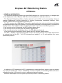
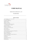
Express E21 Monitoring Station
USER MANUAL
1. GENERAL INFORMATION
The Express21Monitoring Station was specifically designed as a simple solution to manage rapid
on-site deployment of the “Express GSM” line of security detection and alarm devices.
The Express21 Monitoring Station, further referred to as the E21, can be successfully utilized to
manage implemented security protection in housing communities, apartment buildings, office
clusters, warehouse and manufacturing facilities, etc.
The E21 receives via a GSM signal, information regarding the state of protected sites and displays
the gathered details using LED indicators. One indicator represents and corresponds to one deployed
security device. The indicators reflect and display the state of security in the following manner:
- If the security device is Disarmed- the LED indicator glows yellow,
- If the security device is Armed- the LED indicator glows green,
- If the security device has identified an Alarm- the LED indicator glows red.
If the security device transmits a Failure signal, the LED indicator flashes yellow.
The E21 is capable of monitoring the state of up to 50 security devices. The image below shows
an external view of the E21. The LED indicators are labeled 1 to 50 and represent the zones
protected by the E21.
In addition to LED indications, the E21 generates and outputs an Alarm signal in order to connect
to an external strobe light or siren. Additionally, the E21 is capable of transmitting SMS notifications
indicating the state of the security zones to assigned telephone numbers.
Below is a description of how to power-up and set-up the E21 Monitoring Station.
2. INITIAL FIRST TIME POWER-UP
Remove the lid from the upper portion of the E21 housing and install a SIM card in location SIM 1.
De-activate the SIM card PIN code lock feature before using for the first time.
Place the E21 rechargeable battery cell switch into the “ON” position. The E21 contains a built-in
rechargeable battery cell. A fully charged battery cell permits the E21 to operate for six (6) hours. The
battery cell re-charges while the E21 operates via an AC adapter or a USB computer port.
Connect the included AC adapter to the E21 unit and plug it into an external 100V-240V power
source or connect the E21 to an USB computer port.
The POWER LED indicator will glow green to indicate that the E21 is “ON”.
The E21 power state is shown by the LED POWER indicator in the following manner:
Indicator OFF/ not lit
E21 “OFF”
Glows green
E21 “ON”, powered by an external source
E21 “ON”, powered by an external power
Short red flashes on green background
source, battery cell charging
E21 “ON”, powered by the battery cell; no
Flashes green
external power
Flashes yellow
E21 “ON”, battery cell charge almost depleted
While operating on the battery cell, the E21 can be turned “ON” or “OFF” via the POWER button.
When operating using an external power source, this button is not active.
3. ASSIGNING OPERATING PARAMETERS TO THE E21
Furthermore, in order for the E21 to begin operating, a number of simple actions must be executed
to assign operating parameters. This can be executed by using SMS string commands.
After powering-up the E21 for the first time, it is necessary to assign an Administrators telephone
number to the unit. From a random mobile telephone, send the following SMS command to the SIM
card telephone number installed in the E21:
T01=<Administrators telephone number>
Sample command:
T01=+17184403281
The E21 upon acknowledgement of the command, will reply with a confirmation SMS notification,
T01=+17184403281, to the assigned administrators telephone number.
From this point on, assigning operating parameters can only be executed from the assigned
administrator’s telephone number.
Further, it is necessary to assign security zones to the alarm devices together with other additional
parameters.
From the administrator’s telephone, it is necessary to send a command to the E21 telephone
identifying each protected zone. The command consists of the zone number and five (5) parameters.
Some of the parameters are mandatory, while others are optional, and do not need to be included in
the command string. In this event, the E21 will utilize the default parameter values. Mandatory
parameters are highlighted in bold.
F<Security zone number>=<Alarm device telephone number>, <type of device>,
<supervisory time interval>,<telephone number for the receipt of zone
event notifications>,<security zone description>
Parameter descriptions can be found below.
Parameter
Assigned Function
E21 security zone number from 1 to 50. Mandatory
Security zone number
parameter. Indicated in format: 01,02,03….49,50
Telephone number of the on-site device in the following
Device Telephone number
format +1<telephone number>. Mandatory parameter.
Type of on-site device:
S - <<Express GSM>> type of alarm device.
Type of device
Z – Other device type. Not mandatory. By default value
<<S>> used.
Time interval during which the device must transmit to the
E21 event or supervisory notifications. In case the
supervisory time interval is set and the E21 does not receive
any notifications from the device during the set interval, it is
assumed that the connection with the device is lost and the
E21 generates a Failure notification for the security zone.
Supervisory time interval
The interval is set in days, hours, minutes using format:
3 – Days (three days),
10* - hour (ten o’clock)
45# - minutes (forty-five minutes).
Non-mandatory parameter.
By default equals 0 – interval not set, supervision not
enabled.
Telephone number to which E21 transmits SMS notifications
re: security zone events. For example Arming, Disarming,
Telephone number to receive zone
Alarms and other notifications. Telephone number format:
event notifications
+1<Telephone number> Non-mandatory parameter. By
default, no telephone number assigned.
Generic description of the security zone. For example,
address of the secured site.
This description is included in all E21 transmitted SMS
Security zone description label
notifications and zone event journal entries. Non-mandatory
parameter. By default, the description labels are: <<Zone
01>>, <<Zone 02>>, etc.
Example of a short version commands:
F01=+17185551212 – Zone 01 is assigned on-site device bearing telephone number
+17185551212. Other assigned parameters are by default.
Upon receipt of the command, the E21 will assign the on-site device to the security zone and will
reply with the assigned parameters:
F01=+17185551212,S,0,Zone 01
Example of full version commands:
F01=+17185551212,Z,1*,+17185551313, Any Street 5
Reply to the command:
F01=+17185551212,Z,1*,+17185551313, Any Street 5
Zone 01 is assigned security device bearing telephone number +17185551212, type-Z,
supervisory time interval equals 1 hour, telephone number for the receipt of zone event notifications+17185551313, zone label description- Any Street 5.
4. E21 MONITORING STATION OPERATING INDICATORS
After the on-site security devices are assigned to the E21 security zones, the E21 is now ready to
receive and display information from the security devices via the LED zone indicators.
The state of the zones aredisplayed in the following manner.
Security Zone Indicator Lights
State of the Security Zone
Notlit
Zone not in use
Security device is assigned to the zone, but has not yet
Short yellow flashes
received a single notification
Glows steady yellow
Zone disarmed
Glows steady green
Zone armed
Alternate glows green and yellow
Not all alarm circuits of armed device GSM are armed
Glows steady red
Zone alarm
Intermittently flashes red
Fire in the zone
Intermittently Flashes yellow
Failure in the on-site security device; no connection
The LED POWER indicator displays the E21 power state in the following manner.
POWER INDICATOR LIGHT
Indicator OFF/ not lit
Glows green
Short red flashes on green background
Flashe sgreen
Flashes yellow
POWER STATE
E21 “OFF”
E21 “ON”, powered by an external source
E21 “ON”, powered by an external power source, battery
cell charging
E21 “ON”, powered by the battery cell; no external power
E21 “ON”, battery cell charge almost depleted
The LED Failure indicator displays the E21 Failure state in the following manner.
FAILURE INDICATOR LIGHT
Indicator OFF/ not lit
Glows yellow
Flashes yellow
E21 FAILURE
No Failure
Failure present
Number of flashes define reason for Failure
In the event of an E21 Failure, press the SOUND button and the FAILURE LED indicator will
identify with green flashes the reason for the failure.
Number of FAILURE indicator
1
2
3
4
Reason for Failure flashes
No connection between the primary channel and the GSM back-up
No connection on the primary GSM channel
No external power
E21 Malfunction
The GSM LED indicator displays E21 signal strength with the GSM network in the following
manner
GSM INDICATOR LIGHT
Glows steady yellow
Glows steady green
Red flashes on green background
SIGNAL LEVEL STATE
No connection
Normal connection
The E21 has received a notification from the GSM network
In case the E21 identifies an event requiring attention, a long audio signal will be emitted and can
be stopped by pressing the button SOUND.
5. ASSIGNING ADDITIONAL E21 MONITORING STATION PARAMETERS
5.1. RECEIVING GENERALINFORMATION FROM THE E21MONITORING STATION
It is possible to assign the E21 a telephone number to which any security zone changes, occurred
events or the state of the E21 are transmitted.In order to assign this type of telephone number to the
E21, it is necessary to send an SMS command message from the administrator’s telephone to the
telephone number in the E21.
T03=<Telephone number for the receipt of general information>
Sample command:
T03=+17185551212
Upon receipt of the command, the E21 will reply with a confirmation to the administrator’s
telephone.
T03=+17185551212
5.2. PERIODICALLY RECEIVING REMAINING BALANCE INFORMATION
FOR THE
TELEPHONE NUMBER IN THE E21.
In order to receive remaining balance information in regards to the E21 telephone number, it is
necessary to send the following command from the administrator’s telephone. Mandatory command
parameters are highlighted in bold.
T02=<Telephone number to which remaining balance inquiry is sent>,<Low balance
threshold><Interval at which remaining balance inquiry SMS is sent>, <Interval at which low balance
SMS is sent>
Below is a description of the command parameters.
Parameter
Function
Telephone number to which remaining balance
Telephone that will receive balance inquiry SMS
inquiry is sent
response. Mandatory parameter.
USSD sequence for E21 SIM card balance
inquiry from the mobile operator. Non-mandatory
USSD
parameter. E21 automatically selects the
sequence. In this case, it is not necessary to
assign a parameter.
Money amount which represents a critically low
Low balance threshold
balance. Non-mandatory parameter. Default
setting 0-not enabled.
Interval in days at which E21 sends a remaining
Time period interval at which remaining balance
balance notification. Non-mandatory parameter.
SMS is sent
Default setting equals 7 days.
Time interval in days at which E21 sends a low
Notification frequency interval at which low
balance notification. Non-mandatory parameter.
balance SMS is sent
Default setting 0 - not enabled.
Example of a short version commands
T02=+17185551212
Upon receipt of the command, the E21 memorizes the parameters and replies confirming the
assigned parameters:
T02=+17185551212,0,7,0
E21 will transmit a remaining balance SMS notification to telephone number+17185551212 every
7 days; low balance threshold not enabled.
Example of full version commands:
T02=+17185551212,200,5,1
E21 will transmit a remaining balance SMS notification to telephone number+17185551212 every
5 days, low balance threshold set at 200 units and low balance information will be at an interval of 1
day.
In response to the command, E21 sends this confirmation notification:
T02=+17185551212,200,5,1
In order to make a remaining balance inquiry, E21 utilizes the so-called USSD sequence. For
major mobile operators, E21 identifies and employs the required USSD sequence. If necessary, the
USSD sequence can be manually assigned in E21 parameter set-up.
USSD command task sequence for SIM 1:
l01=<USSD sequence>
Sample command:
l01=*100#
Response:
l01=*100#
USSD command task sequence for SIM 2:
l02=<USSD sequence>
Sample command:
l02=*102#
Response:
l02=*102#
5.3. RECEIVING REMAINING BALANCE INFORMATION ON COMMAND
In order to receive the current balance remaining on the E21 telephone number, it is necessary to
send from the administrator’s telephone the following command- word:
Balance
E21 will respond to the inquiring telephone number with a remaining balance notification.
6. SERVICE COMMANDS FOR THE E21 MONITORING STATION
6.1. INQUIRING AND RECEIVING CURRENT E21 SECURITY ZONE
PARAMETER SETTING
INFORMATION
In order to receive current security zone settings, send from the administrator’s telephone to the
E21 telephone number the following command:
F<Number of the security zone for which the parameter inquiry is being made.>
Sample command:
F12
In response, E21 sends security zone parameters in the following format:
F<Number of the security zone>=<Telephone number of the alarm device>,<Device type>,
<Supervisory time interval>,<Telephone number for the receipt of security zone
event
notifications>,< Security zone description label>
6.2. INQUIRING AND RECEIVING INFORMATION ABOUT ASSIGNEDON-SITE ALARM DEVICES
In order to receive information about assigned on-site alarm devices and their security zone
settings, it is necessary to send from the administrator’s telephone to the E21 telephone number the
following command:
F<Telephone number of the on-site alarm device>
Sample command:
F+17185551212
The reply SMS message will contain the security zone parameter settings of the assigned alarm
device:
F<Number of the security zone>=<Telephone number of the alarm device>,<Device type>,
<Supervisory time interval>, <Telephone number for the receipt of security zone
event
notifications>,< Security zone description label>
6.3. COMMAND <<ASSIGN THE INTERVAL FOR VERIFYINGREGISTRATION ON THE PRIMARY
CHANNEL>>
l03=<interval for verifying registration on the primary channel (in hours)>
Sample command:
l03=2
Response:
l03=2
6.4. COMMAND<<ACTIVATE THE SOUND INDICATOR FOR INCOMING SMS>>
l04=< 1- Permit short sound for incoming SMS,0- Restrict sound for incoming SMS>
Sample command:
l04=1
Response:
l04=1
7. E21 MONITORING STATION EVENT LOG
7.1. VIEWING THE EVENT LOG
The E21 retains in it’s memory all events occurring in the security zones together with important
E21 operating incidents related to power on/ off, GSM signal interruption and re-establishment of
GSM signal. The E21 records 1000 recent events/ incidents, saves them in a file designated as
LOG.TXT and stores them in the E21 memory. The file can be viewed and read by connecting the
E21 via cable to a USB computer port. The E21 memory can be accessed via a computer, in a
manner similar to accessing an external hard or flash drive.
In order for the E21 to create a new file, LOG.TXT, that will contain recent events and incidents, it
is necessary to press the refresh button located on the front panel of the E21 unit. Then it is
necessary to access the E21 memory (similar to accessing an external computer drive) and open the
LOG.TXT file using a program that reads text files, e.g. Notepad.
7.2. SETTING UP THE CURRENT TIME IN THE E21 EVENT LOG
In order for the E21 to indicate time of occurrence in the event log, it is necessary to assign the
current time to the E21. To accomplish this, while connected to a computer it is necessary to create a
file named TIME-GSM.TXT in the root directory. The time the computer generates when the file is
written to the device memory will be established as the current time of the device. The file contents
have no value.
8. ASSIGNING E21 MONITORING STATION OPERATINGPARAMETERS BY MEANS OF THE
CONFIGURATION FILE
Found inside the E21 memory root directory is the LOAD.TXT file containing an E21 operating
parameters template. Open the file using Notepad or any similar program. The file contains entries
such as the administrator’s telephone number, a telephone number to receive E21 remaining balance
information, a telephone number to receive E21 general info and entries showing E21 assigned
security zone parameters.
Entries are created using the same rules as for sending SMS commands to the E21 Monitoring
Station. For example, the administrators telephone number needs to be assigned in the following
manner:
T01=+17185551212
Assigning the telephone number to receive remaining balance, e.g.:
T02=+17185551213
Assigning the telephone number to receive security zone parameters, e.g.:
F01=+17185551214
or
F01=+17185551214,Z,1*,+17185551215,ANY STREET 5
After making the appropriate entries, save the file and copy it to the CFG directory in the E21’s
memory, press the DOWNLOAD button located on the front of the E21 panel. The E21 Monitoring
Station is now ready to operate using the new parameters.
9. USING TWO SIM CARDS WITH THE E21 MONITORING STATION
In order to ensure a high level of communication reliability, the E21 possesses the ability to utilize
two SIM cards; primary and back-up. In order to operate the E21, it is sufficient to only use the
primary SIM card installed in SIM card holder No. 1. The back-up SIM card installs in SIM card holder
No. 2.
When two SIM cards are installed, if the primary SIM card loses it’s GSM network signal for more
than 5 minutes, the E21 will automatically switch to the back-up SIM card. After operating on the
back-up SIM card for an hour, the E21 device will attempt to re-establish a connection using the
primary SIM card. In the event the connection is successfully re-established, the E21 will continue
operating on the primary SIM card.
In order to avoid the back-up SIM card from being de-activated by the mobile provider due to a
long period of inactivity (usually a period of more than 3 months), the E21 will automatically switch to
and operate on the back-up SIM card every 30 days for 1 hour and then switch back to operating on
the primary SIM card. During this occurring event, an SMS notification is sent showing the back-up
SIM card remaining balance.
10. CONTACT US
ALPHA ARSENAL, LLC
104-20 Queens Blvd., Ste 1B
Forest Hills, NY 11375, US
T/F: +1.718.440.3281
+1.718.355.9281
Skype: alpha.arsenal
E-mail:
[email protected]
[email protected]
Website:
www.alpha-safe.com