1
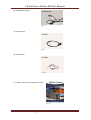
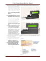
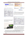
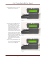
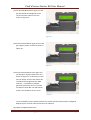
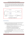
User Manual
Find’n’Secure Starter Kit
Embarc Information Technology (P) Ltd
39, Old Vijay Nagar Colony, Agra -282 004, India.
Tel: +91 (562) 2857222, E-Mail: [email protected] Web: www.findnsecure.com
UK: +44 20 81449750 (Phone), +44 70 06035630 (Fax)
Find’n’Secure Starter Kit User Manual
Copyright © August 15, 2007
Embarc Information Technology (P) Ltd. All rights reserved
Embarc Document
Printed in India
Notice
This manual, as well as the software described in it, is furnished under license and may be used
or copied only in accordance with the terms of such license. The content of this manual is
furnished for informational use only, is subject to change without notice, and should not be
construed as a commitment by Embarc I.T. (P) Ltd. Embarc I.T. (P) Ltd. assumes no responsibility
or liability for any inaccuracies that may appear in this book.
Embarc I.T. (P) Ltd reserves the right to make changes to specifications at any time and without
notice. The information furnished by Embarc I.T. (P) Ltd. in this publication is believed to be
accurate and reliable; however,Embarc I.T. (P) Ltd. assumes no responsibility for its use, or for
infringements of patents or other rights of third parties resulting from its use. No license will be
granted under any patents or patent rights owned by Embarc I.T. (P) Ltd.
Check for updated version of user manual at:
www.findnsecure.com/downloads/starterkit_manual.pdf
© Embarc Information Technology (P) Ltd 2007
www.findnsecure.com
Page 2
Find’n’Secure Starter Kit User Manual
Contents
Introduction ............................................................................................................................................ 4
Package Contents.................................................................................................................................... 4
Before you start ...................................................................................................................................... 6
Configuration of Vehicle unit .................................................................................................................. 6
Testing in the vehicle ............................................................................................................................ 11
Appendix A ............................................................................................................................................ 11
Procedure to switch from GPRS mode to SMS mode ....................................................................... 14
Appendix - B .......................................................................................................................................... 14
Procedure to create a free account with DynDNS ............................................................................ 14
© Embarc Information Technology (P) Ltd 2007
www.findnsecure.com
Page 3
Find’n’Secure Starter Kit User Manual
Introduction
Congratulations for purchasing the Find’n’Secure starter kit. This kit will help you get going in no
time to enable you to test the Find’n’Secure AVLS (Automatic Vehicle Location and Security) System.
Package Contents
The starter kit contains the following items:
(1) Vehicle Unit
Figure 1
(2) LCD Display
(3) GPS and GSM Antenna
Figure 2
Figure 3
© Embarc Information Technology (P) Ltd 2007
www.findnsecure.com
Page 4
Find’n’Secure Starter Kit User Manual
(4) Configuration Cable
Figure 4
(5) Wiring Cable
Figure 5
(6) Panic Switch
Figure 6
(7) Embarc Vehicle unit configuration utility
Figure 7
© Embarc Information Technology (P) Ltd 2007
www.findnsecure.com
Page 5
Find’n’Secure Starter Kit User Manual
Before you start
Before you proceed for the configuration of the vehicle unit, following information should be known:
(1) Mobile no. of the SIM for the vehicle unit : The SIM should be preferably post paid GPRS
enabled SIM with sufficient credit
(2) Vehicle id: This vehicle id number will normally be automatically generated by the
Find’n’Secure AVL software on adding vehicle units to groups or you can even have user
defined vehicle ids. We will send you the vehicle id separately for the starter kit.
(3) Frequency: You need to decide the frequency at which data packets are to be sent when the
vehicle is in motion, minimum displacement (in meters) before data packet is sent and the
frequency at which data packets are sent when the vehicle is stationary. The default value is
20 sec (while moving), 240 sec (while stationary) and 40 m minimum displacement. Default
values should normally be used.
(4) GPRS username: It is provided by the GSM provider. In some cases there is no username.
Leave blank in that case.
(5) GPRS password: It is provided by the GSM provider. In some cases there is no username.
Leave blank in that case.
(6) APN Name: APN (Access Point Name) is provided by the GSM provider.
(7) Dial Number: It is generally *99***1# but in vehicle units having Ericsson mobile phones it is
*99***9#
(8) Domain: You have to create an account with www.DynDns.org and enter that here.
Procedure to create account with DynDns is given in Appendix B. You can update the ip using
DynDns updater or any similar utility. Use manual update option for the starter kit with ip as
122.160.144.32 (IP of our server)
(9) DNS IP: Provided by carrier. If the carrier doesn’t give leave in blank and unit will auto detect
it. Normally it is left as blank only.
Install the Embarc Vehicle Unit Configuration Utility (supplied on CD) on any PC running Windows XP
/ Vista and having active internet connection. The PC should also have a free COM port (either COM1
or COM2)
Configuration of Vehicle unit
(1) Connect LCD display to the vehicle unit
(Figure 8).
(2) Connect the GSM antenna (short
antenna) and the GPS antenna to the
appropriate connectors of the vehicle
unit (See Figure 9) with the non
magnetic side of the GPS antenna
facing the sky.
Figure 8
© Embarc Information Technology (P) Ltd 2007
www.findnsecure.com
Page 6
Find’n’Secure Starter Kit User Manual
(3) Connect one end of the configuration cable to the COM Port (COM1 or COM2 as the case
may be) of the PC and the other
end to the 15 Pin D type connector
of the vehicle unit and the power
adapter of the configuration cable
to mains and power on. You will
see on the LCD display as shown in
Figure 9:
(4) In the vehicle unit’s LCD, press the
black button until you see “PA:” in
the first line and “Op:” in the
second line (which refers to the
Figure 9
last command received by the
unit). This will be useful to verify
that there is communication
between base and unit (See Figure
10)
(5) Make sure that the vehicle unit is
in SMS mode before attempting
to configure it in GPRS mode. XPGSM (in Figure 9) confirms it is in
SMS mode. If you see XP-GPRS
instead it is in GPRS mode. If it is
in GPRS mode it needs to be
reverted to SMS mode first as per
procedure given in Appendix A.
(6) Start the Embarc Vehicle unit configuration utility on the PC and select GPRS mode. Select
the correct COM port.
(7) Enter vehicle id (six digit number
Figure 10
assigned by Find’n’Secure AVL
software or sent by us), VU
Mobile and Frequency settings.
(8) Enter Username (if applicable),
password (if applicable), APN
name, Dial number (if different)
(See Figure 11)
Figure 11
© Embarc Information Technology (P) Ltd 2007
www.findnsecure.com
Page 7
Find’n’Secure Starter Kit User Manual
(9) Enter Domain (created using
www.DynDns.org), DNS IP (if applicable).
Leave local port and remote port as it is
(See Figure 12). Inform the domain name
to us too.
(10)Click on Send to VU (See Figure 13).
Figure 13
(11) After few seconds you will see commands
like SPB, SPC etc on the LCD display and after that
the vehicle unit will automatically restart and you
will get the following screen (See Figure 14):
Figure 12
You will also see the vehicle unit restarting
(with ID changed to new one) as shown
below (See Figure 15):
Figure 14
(12)
Now it will try to connect to GPRS
but will not be able to do so because SIM is not
present inside the vehicle unit. At this point power
off the vehicle unit (remove power adapter of
configuration cable from mains) open the four
Figure 15
screws on the base of the vehicle unit, insert
the SIM and power on the vehicle unit from a 12V Battery using the provided black cable in
which red wire is connected to +12V and Black wire connected to GND.
(13) To check whether vehicle unit has been properly configured, once the vehicle unit has
booted press black black button repeatedly and you should see displays similar to the
following:
© Embarc Information Technology (P) Ltd 2007
www.findnsecure.com
Page 8
Find’n’Secure Starter Kit User Manual
(14)The display in Figure 16 shows that
GPRS has been connected OK.
Figure 16
(15) Press black button again and you
see a display similar to the one
shown in Figure 17. The number on
top left (07:27) is the UTC Time,
<STOP> signifies that the vehicle is
stationary at the moment, the
number on top right (0018) is the
seconds till which it will wait before
sending a data packet. The number
on bottom left (08/11) is the current
date. The number (T:04/04) below
<STOP> signifies the satellites visible
to the GPS antenna and 3D-OK
signifies that the GPS fix has been
achieved.
(16) On pressing the black button again
you will see the details of satellites
visible as shown in Figure 18
Figure 17
Figure 18
© Embarc Information Technology (P) Ltd 2007
www.findnsecure.com
Page 9
Find’n’Secure Starter Kit User Manual
(17) On pressing black button again you will
get the latitude and longitude of the
current location similar to the one
shown in Figure 19
Figure 19
(18) Press the black button again and you will
get a display similar to the one shown in
Figure 20
Figure 20
(19) Press the black button once again and
you will get a display similar to the one
shown in Figure 21. In this there are two
lines of display. The first line shows UIP:
117.96.10.212 (assigned by the GSM
operator – it could be any number
generally of the form 10.x.x.x) and the
second line shows BIP: 122.160.144.32
which is the IP address of our server.
Figure 21
If you see display screens similar to above, the vehicle unit would be properly configured.
Repeat steps 7 to 10 for other vehicle units (if required).
(20) When completed press Done
© Embarc Information Technology (P) Ltd 2007
www.findnsecure.com
Page 10
Find’n’Secure Starter Kit User Manual
Testing in the vehicle
To test in the vehicle the wiring cable is to be used. The red and black wires are to be connected to
the positive and negative terminal of the car battery. The 15 Pin D type connector should be
connected to the vehicle unit and LCD display should also remain connected. The GPS antenna can
be kept on the car roof during testing. The vehicle should be taken around and it should report on
the software moving in real time. Read the user manual of Find’n’Secure for more details on the
software. You can download it from here.
Wiring Diagrams for Model FS-11
(A)
Triggers
(1) Below is the wiring diagram to connect the optional battery (Z-Event). When the red cable is
disconnected from +12V terminal the unit sends a Z-Event to the base station. Also the unit
will send an alert when the red cable is reconnected.
(2) Y- Event: Connect the green cable to the –ve terminal of the battery and the unit will send a
Y event to the base. Also the unit will send an alert when the green cable is disconnected.
(3) X-Event: Connect the brown cable to the +12V terminal of the battery and the unit will send
a X-event to the base. Also the unit will send an alert when the brown cable is disconnected.
© Embarc Information Technology (P) Ltd 2007
www.findnsecure.com
Page 11
Find’n’Secure Starter Kit User Manual
(B)
Outputs
(1) There are three outputs in this vehicle unit. Two outputs (Blue wire and orange wire) source
5mA current and the third output (white wire) is able to sink 200mA current. Below is the
circuit diagram for output A and output B. Since the Blue or orange wire sources around
5mA current, it cannot drive a relay directly hence it needs to be amplified. The below circuit
amplifies the signal from blue or orange wires to one which is good enough to drive a relay.
The output can be used to either blow horn or open doors (in cars having central locking
feature) or any other use which can be thought of.
© Embarc Information Technology (P) Ltd 2007
www.findnsecure.com
Page 12
Find’n’Secure Starter Kit User Manual
(2) Below is the wiring diagram for ignition kill. The ignition circuit is bypassed and connected
via a 12V relay. The relay is normally closed and the circuit is complete. When the ignition
block command is issued from web or mobile the white wire causes the relay to energise
and the connection opens to kill the engine. On issuing the ignition unblock command from
web or mobile the relay de-energises and the connection closes thereby the ignition circuit
is again complete.
Trouble Shooting
(1) No display on LCD: Check whether the connector has been inserted in the right direction.
Also check whether the male / female connectors mating have happened correctly.
(2) GPRS Not Connected: This could be for variety of reasons
a. The GSM Antenna not connected to the connector (near the GSM board)
b. The SIM is not GPRS enabled – To confirm this insert the SIM in a mobile phone and
see whether you are able to surf the internet or not.
c. APN information is not correct – Check the same from GSM provider
d. Username / Password – Check the same from GSM provider
e. Try using SIM from any other GSM provider if available
f. Area where you are working does not have proper GSM coverage
g. After configuring the vehicle unit should be run on a 12V battery or a bigger power
source (using the black cable)
(3) Pos Hold or No Position: The GPS Antenna should be placed such that the black curved
surface should face the clear sky.
(4) No report on software: Take the unit around in a vehicle and then see. Also check whether
vehicle id is correct.
© Embarc Information Technology (P) Ltd 2007
www.findnsecure.com
Page 13
Find’n’Secure Starter Kit User Manual
Appendix A
Procedure to switch from GPRS mode to SMS mode
When the LCD is not showing "Connecting" press the black button for 16 seconds without releasing
it.
1) You should see "Please wait 16 sec. Dont press any button" appear in the LCD. Ignore the
warning.
2) Now type the following sequence of buttons in the LCD, where 1=WHITE and 2=GREY: 2122
1211 12
3) After this you should see: "Reconfigure to SMS ? White=YES, Grey=NO"
4) Then press the WHITE button in the LCD to switch back to SMS.
After this the vehicle unit will revert back to SMS mode.
Appendix - B
Procedure to create a free account with DynDNS
To create a free account go to
https://www.dyndns.org/account/create.html
Complete all requested data and put a valid email address to be able to activate the account.
Then Click ”CREATE ACCOUNT”. You will receive an email with instructions to activate the
account, just follow the instructions to proceed.
Login to your account by going to:
https://www.dyndns.org/account/login.html
Create your own Dynamic DNS Host by going to:
https://www.dyndns.org/account/services/hosts/dyndns/add.html
Select your own Domain_Name_Base, for example:
yourcompany -> dynalias.net
Then click "Add Host" and you’re done. Logout to finish.
After creating an in DynDNS above then you will need to update the IP address of the server using an
update client like DynDNS updater which can be downloaded from
http://www.dyndns.com/support/clients/
© Embarc Information Technology (P) Ltd 2007
www.findnsecure.com
Page 14