1
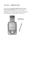
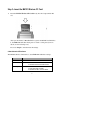
NETGEAR
®
IEEE 802.11b Wireless CF Card
11 Mbps
MA701
User’s Guide
.
NETGEAR, INC.
4500 Great America Parkway
Santa Clara, CA 95054
USA
Phone: 1-888-NETGEAR
E-mail: [email protected]
www.NETGEAR.com
Technical Support
YOU MUST REGISTER TO OBTAIN TECHNICAL SUPPORT. PLEASE
RETAIN PROOF OF PURCHASE AND THE WARRANTY
INFORMATION.
To register your product, get product support or obtain product information
and product documentation, go to http://www.NETGEAR.com/register.
You’ll find technical support information at http://www.NETGEAR.com/
through the Customer Service area. If you want to contact technical support
by telephone, see the support information card for the correct telephone
number for your country.
© 2002 by NETGEAR, Inc. All rights reserved.
NETGEAR is a trademark or registered trademark of NETGEAR, Inc. in the
United States and/or other countries.
Other brand and product names are trademarks or registered trademarks of
their respective holders.
Information is subject to change without notice.
CONTENTS
CHAPTER 1—INTRODUCTION ........................................................................................................3
Features.........................................................................................................................................4
Package Contents..........................................................................................................................4
About This Guide ...........................................................................................................................5
Ready, Set, Go! .............................................................................................................................5
CHAPTER 2—INSTALLATION .........................................................................................................6
System Requirements....................................................................................................................6
Step 1—Preparation ......................................................................................................................7
Step 2—Install the MA701 Driver and Utility..................................................................................7
Step 3—Insert the MA701 Wireless CF Card ................................................................................9
Step 4—Configure the Network Settings .....................................................................................10
Step 5—Test For Wireless Access ..............................................................................................13
CHAPTER 3—CONFIGURING THE MA701 WIRELESS CF CARD ..............................................15
Status Property Page...................................................................................................................16
Configuration Property Page........................................................................................................19
Security Property Page ................................................................................................................22
Ping Property Page......................................................................................................................24
Performance Property Page ........................................................................................................25
AP Browser Property Page ..........................................................................................................26
About Property Page....................................................................................................................27
CHAPTER 4—WIRELESS NETWORK FUNDAMENTALS ............................................................28
Wireless Network Configuration...................................................................................................28
Ad-hoc Mode (Peer-to-Peer Workgroup)................................................................................28
Infrastructure Mode.................................................................................................................29
Service Set Identification (SSID)..................................................................................................30
Authentication and WEP Encryption............................................................................................30
Wireless Channel Selection .........................................................................................................32
APPENDIX A—TROUBLESHOOTING............................................................................................33
APPENDIX B—GENERAL SPECIFICATIONS ...............................................................................34
APPENDIX C—REGULATORY COMPLIANCE..............................................................................35
2
CHAPTER 1—INTRODUCTION
Thank you for purchasing NETGEAR’s IEEE 802.11b Wireless Compact
Flash Type I Card, Model MA701. With this new Wireless Compact Flash
Card, your Handheld PC (Windows CE 2.11 or above) and Pocket PC
(Windows CE 3.0) can take advantage of wireless access to your corporate LAN,
surf the Internet, access e-mails, and communicate with other mobile devices
enabled for IEEE 802.11b standard-based wireless LAN connectivity.
MA701 Wireless
Compact Flash Card
3
Features
The key features of the IEEE 802.11b Wireless Compact Flash Card, Model
MA701 are:
♦
Reliable IEEE 802.11b standards-based wireless technology designed for
multi-vendor compatibility.
♦
Fast data transfer speeds up to 11 Mbps.
♦
Easy installation on all Pocket PCs and Handheld PCs with Compact Flash
Type I or Type II card slots.
♦
Supports multiple data rates, including 1, 2, 5.5 and 11 Mbps, with an auto
fallback feature to ensure dependable connectivity.
♦
Built-in privacy protection supports both 40/64 and 128-bit WEP (Wired
Equivalent Privacy) encryption systems.
♦
Offers a wireless range up to 300 feet in an office environment.
Package Contents
This product package should contain:
♦
IEEE 802.11b 11 Mbps Wireless
Compact Flash Card, Model MA701
♦
CD-ROM with Driver and Utility
Installation Wizard
♦
This User’s Guide
♦
Warranty and Registration Cards
♦
Support Information Card
4
About This Guide
This User’s Guide will show you how to install and use NETGEAR’s Wireless
Compact Flash Card, Model MA701. With a few simple steps, you can connect
your Windows CE-based PDA via the 802.11b Wi-Fi certified Access Point (AP)
into an existing network for secure Internet access.
Throughout this guide, only Pocket PC screen shots are displayed. Handheld PC
2000 and Handheld PC Pro screens will be functionally equivalent.
Ready, Set, Go!
The Wireless Compact Flash Card, Model MA701 is easy to install. You need
only to complete these five steps, which should take about 10 to 15 minutes:
Preparation.
Install the MA701 Driver and Utility software.
Insert the MA701 Wireless CF Card.
Configure the network settings.
Test for wireless access.
To start the installation process, turn to page 6, Chapter 2—Installation.
5
CHAPTER 2—INSTALLATION
This chapter provides step-by-step instructions to install the IEEE 802.11b
Wireless Compact Flash Card, Model MA701.
System Requirements
Before installing the MA701 Wireless CF Card, please make sure that these
requirements have been met:
♦
You must have a Pocket PC 2000/2002 (P/PC), or Handheld PC (H/PC)
with a Compact Flash Type I or II slot.
♦
The Windows CE version should be V2.11 or higher.
♦
There should be at least 500 Kbytes of free memory on your P/PC or H/PC.
♦
You must have a Desktop PC or Laptop PC with Microsoft ActiveSync
software successfully installed. This PC will be used for installing the
MA701 Driver and Utility software to your Pocket PC or Handheld PC.
6
Step 1—Preparation
Before beginning the installation, please perform these steps:
1.
Verify the package contains a MA701 Wireless CF Card and a MA701
Driver and Utility Installation Wizard CD.
2.
Make sure your Pocket PC or Handheld PC is equipped with a Compact
Flash Type I or II slot.
3.
Make sure your target Pocket PC or Handheld PC has at least 500 Kbytes
free memory for the MA701 Driver and Configuration Utility.
4.
Establish a connection between the host PC and your PDA using Microsoft
ActiveSync software.
Step 2—Install the MA701 Driver and Utility
To install the MA701 Wireless CF Card Driver and Utility software, follow
these steps:
1.
Make sure you have an ActiveSync connection between the host PC and
your Pocket PC or Handheld PC with a serial or USB cable.
2.
Make an active partnership between your Pocket PC or Handheld PC and
the host PC.
3.
On the host PC, insert the MA701 Driver and Utility CD into the CDROM drive.
7
4.
On the host PC, double-click My Computer, then double-click the CDROM drive where the MA701 Driver and Utility CD is located.
5.
Double-click the Pocket PC or Handheld PC file folder.
6.
Double-click SETUP.EXE to launch the installation wizard and follow the
instructions displayed on the screen.
7.
Click Yes to install the utility using the default application installation
directory.
8.
Click the Finish button to complete the installation.
9.
Disconnect your Pocket PC or Handheld PC from the host PC.
10. Press the reset button on your Pocket PC or Handheld PC.
Upon successful installation of the MA701 Driver and Utility software, a
MA701 icon will be created under Programs on your Pocket PC or Handheld
PC. Tap this icon to start the MA701 Configuration Utility.
8
Step 3—Insert the MA701 Wireless CF Card
♦
Insert the MA701 Wireless CF Card directly into the Compact Flash I/O
slot.
After your Pocket PC or Handheld PC recognizes the MA701 and initializes
it, the Link LED will either flash green or remain a solid green (for more
details, see the following note).
Proceed to Step 4 to enter the network settings.
A Note About the LED Indicator
The MA701 Wireless CF Card has a status Link LED with these settings:
LED STATUS DESCRIPTION
Off No Power
Solid Green Indicates: 1. Associated with the Access Point, or
2. Connected to an Ad-hoc wireless device.
Flashing Green Indicates: 1. Not connected to the Access Point, or
2. Power Save Mode is enabled.
3. Connected to a 802.11 Ad-hoc network.
9
Step 4—Configure the Network Settings
This step configures your Pocket PC or Handheld PC with the MA701 Wireless
CF Card in Windows CE.
Note: For detailed information on wireless networking, refer to Chapter 4—
Wireless Network Fundamentals, page 28.
1.
Select Settings and then tap the Network Adapters option.
2.
Select the NETGEAR MA701 Wireless CF Card entry.
10
3.
Tap the Properties button to open the IP Settings page.
4.
Enter the appropriate IP address information for the MA701 Wireless CF
card and then tap OK.
Note: If you are unsure of the IP related information, please contact your
network administrator or MIS staff personnel.
5.
Tap the MA701 icon from Programs and open the MA701Configuration
Utility. It will automatically open the Status page to display the current
Link status, as shown on the next page.
11
6.
Use the Status, Configuration, Security, Ping, Performance, AP
Browser, and About tabs to view or adjust the MA701 Wireless CF Card
configuration settings.
The default settings are:
♦
SSID: ANY
♦
Mode: Infrastructure
♦
Encryption (WEP): Disabled
7.
Tap Apply to save your configuration settings.
8.
Tap OK on upper right-hand corner to close the MA701 Configuration
Utility status screen.
12
Note: For additional information on using the MA701 Configuration Utility,
please refer to Chapter 3—Configuring the MA701 Wireless CF Card on page
15.
Step 5—Test For Wireless Access
Follow these steps to verify that the MA701 Wireless CF Card has been
successfully installed and that your wireless access is functioning properly.
1.
Open the MA701 Configuration Utility and tap IP Status from the Status
page to view IP related information (shown below). A valid IP address
should be assigned for the MA701 Wireless CF Card.
2.
Tap OK in the IP Status page to close it.
13
3.
Tap the Ping option to test the data transmission between your Pocket
PC or Handheld PC and other computers, such as the host PC.
4.
Enter the IP address of the other PC or the device you need to Ping to,
and then tap Start to begin the test.
5.
If the Ping test is successful, it will display the reply information in the
list box. Once this occurs, your Pocket PC or Handheld PC will have
the correct wireless connection settings to access the net.
14
CHAPTER 3—CONFIGURING THE MA701
WIRELESS CF CARD
Now that you have successfully installed the MA701 Wireless CF Card, you can
use the MA701 Configuration Utility to view and customize configuration
settings and features.
The MA701 Configuration Utility contains seven Property Pages:
1 - Status
2 - Configuration
3 - Security
4 - Ping
5 - Performance
6 - AP Browser
7 - About
Note: The above Property Pages are always available from the bottom of the
MA701 Configuration Utility window.
This utility provides you with wireless network and link quality information for
the MA701 Wireless CF Card.
The Configuration Utility includes two useful utilities—Ping and AP Browser.
Use these if you need help with troubleshooting any wireless connection-related
issues that may arise.
15
Status Property Page
The Status page of the MA701 Configuration Utility displays the current
condition of your wireless LAN, and is the default page that will be displayed:
.
To see a detailed description of the IP Status page options, please refer to the
table on the next page.
16
This table describes the Status page of the MA701 Configuration Utility.
STATUS
DESCRIPTION
Connected to
This field displays the association of the access point (SSID) or other wireless
nodes in Ad-hoc mode.
AP MAC
Addr
(BSSID)
Shows the MAC address of the associated access point (AP) when the MA701
Wireless CF Card is configured in infrastructure mode, or the BSSID if it is
configured in Ad-hoc mode and 802.11 Ad-hoc mode.
Mode
Channel
Link Rate
Encryption
IP Status
Indicates the current Network mode used -- 802.11 Ad-hoc mode, Ad-hoc
mode, or Infrastructure mode. The default value for Network mode is
Infrastructure.
• 802.11 Ad-hoc mode: The wireless nodes form their own local network
where the end nodes communicate peer-to-peer without an access point.
• Ad-hoc mode: Similar to 802.11 Ad-hoc but with less restriction.
• Infrastructure mode: The wireless node searches all available wireless
channels to associate with an access point.
Shows the current channel in use.
Shows the current transmit data rate of the wireless node. The possible link
rates are 1, 2, 5.5, and 11 Mbps. In Ad-hoc mode, this field shows what the
wireless node is configured to use. When in Infrastructure mode, it shows the
result of the transfer rate negotiated between the access point and the wireless
node.
This field indicates if the WEP encryption is enabled or disabled.
This button will display the IP Address information related to the MA701
Wireless CF Card: IP Address, Subnet Mask, the Default Gateway, DHCP
Server, and the MAC Address.
17
From the Status page, tap IP Status to display this page:
When you have finished making any changes, tap the OK button from the IP
Status page to continue.
18
Configuration Property Page
The Configuration page of the MA701 Configuration Utility lets you change
the current network settings related to the MA701 Wireless CF Card.
From this page, you can configure various wireless LAN parameters. Please
refer to the chart on the following table for specific details.
When you have finished making your changes, tap Apply. If you have made
changes but do not want to save them, you can tap Defaults to return them to the
manufacturer’s default settings.
19
The table, shown below and continued on the next page, describes the
Configuration page of the MA701 Configuration Utility.
CONFIG
SETTINGS
DESCRIPTION
Network Mode
Indicates the current Network mode configured, as listed below.
• 802.11 Ad-hoc mode—The wireless nodes form their own local network
where the end nodes communicate peer-to-peer without an access
point. The same SSID and Channel are required for 802.11 Ad-hoc
mode.
• Ad-hoc mode—Similar to 802.11 Ad-hoc but only needs to set the
same Channel.
• Infrastructure mode—The wireless node searches all available
wireless channels to associate with an access point.
Default: Infrastructure
Network SSID
(Service Set ID)
Enter a 32-character (maximum) service set ID in this field; the characters
are case sensitive. When in Infrastructure mode, this field defines the
service set ID (SSID). The SSID assigned to the wireless node is required
to match the access point SSID in order for the wireless node to
communicate with the access point.
Default: ANY
Link Rate
This field shows the current transmit data rate of the wireless node. The
possible link rate selections are 1, 2, 5.5, or 11 Mbps and Fully Auto. In
Ad-hoc mode, this field shows what the wireless node is configured to use.
When in Infrastructure mode, it shows the result of the transfer rate
negotiated between the access point and the wireless node.
Default: Fully Auto
Channel
Shows the current channel and frequency in use. The wireless channel in
use will be between 1 to 11 for US and Canada, and 1 to 13 for Europe
and Australia.
Power
Management
Enables the MA701 Wireless CF Card to enter sleep mode to conserve
battery power.
Default: Off
20
CONFIG
SETTINGS
DESCRIPTION
Fragmentation
Threshold
This is the packet length used for fragmentation. Packets larger than the
size programmed in this field will be fragmented. The Fragment Threshold
value must be larger than the RTS Threshold value.
Default: 2346
RTS Threshold
The packet size that the wireless node uses to determine if it should use
the CSMA/CD mechanism or the CSMA/CA mechanism for packet
transmission. With the CSMA/CD transmission mechanism, the
transmitting station sends out the actual packet as soon as it has waited
for the silence period. With the CSMA/CA transmission mechanism, the
transmitting station sends out an RTS packet to the receiving station, and
waits for the receiving station to send back a CTS packet before sending
the actual packet data.
Default: 2342
Preamble Type
A long transmit preamble allows the receiver to lock into the received bit
patterns more easily. A short transmit preamble provides better
performance.
Default: Long
Defaults
Apply
Tap Defaults to restore to default settings.
Tap Apply to save and make any changes take effect.
21
Security Property Page
The Security page of the MA701 Configuration Utility allows you to enable the
WEP (Wired Equivalent Privacy) for secure wireless data transmission. Please
refer to Chapter 4—Wireless Network Fundamentals on page 28 for details.
The 64-bit or 128-bit WEP keys can be generated from a user-defined
Passphrase by selecting the Create with Passphrase option, or entered
manually by selecting Manual Entry.
Click Apply to save changes or Undo to not save changes.
22
This table shows the Security parameters of the MA701 Configuration Utility.
SECURITY
Encryption (WEP)
Passphrase
DESCRIPTION
The MA701 Wireless CF Card supports 64 or 128-bit WEP data
encryption. (64-bit WEP data encryption is also called 40-bit WEP data
encryption by some vendors.) This parameter enables/disables
encryption and selects the 64 or 128-bit WEP data encryption key to
use.
You need to enter 10-digit hexadecimal values for 64-bit encryption or
26 digit hexadecimal values for 128-bit encryption.
Default: Disabled
The Passphrase can be a text string with a maximum of 31 alpha-numeric
characters.
Key 1
One of the data encryption keys defined in the MA701 Wireless CF
Card. Each data encryption key contains 10/26 hexadecimal numbers,
making it 40/104 bits wide. This combined with the twenty-four factoryset bits, makes up a 64/128-bit encryption key.
Note: Only Key 1 is available for 128-bit encryption.
Key 2
One of the four 64-bit data encryption keys defined in the MA701
Wireless CF Card.
Key 3
One of the four 64-bit data encryption keys defined in the MA701
Wireless CF Card.
Key 4
One of the four 64-bit data encryption keys defined in the MA701
Wireless CF Card.
23
Ping Property Page
The Ping page of the MA701 Configuration Utility lets you perform a data
transmission test to evaluate if your wireless access connections are working
properly.
The data transmission test sends an ICMP ping packet across the network to a
pre-configured address to test data transmission between the MA701 Wireless
CF Card and other network nodes.
Use the Host field to enter the IP address or Web address of the target device
(i.e.: 10.1.1.122). You may also choose different size ICMP packets, as well as
choose to run a continuous test or a test for the specified count.
24
Tap Start to perform the ping test. The round-trip time that each ICMP ping
takes to complete the test will be displayed. The minimum, maximum and
average round-trip time are displayed in the Statistics section.
Tap Stop to end the ping test.
Performance Property Page
The Performance page of the MA701 Configuration Utility displays a real-time
graph of the radio signal transmission strength and the link quality from the
MA701 Wireless CF Card to the associated Access Point. It also periodically
updates the throughput of the transmitted and received packets.
25
AP Browser Property Page
The AP Browser page of the MA701 Configuration Utility displays a list of the
Access Points that have been detected by the MA701 Wireless CF Card.
The SSID, MAC Address, Channel in use, Signal Strength, WEP information
will be displayed.
Tap Rescan to update the list of known Access Points.
Note: This page is only applied while in Infrastructure mode.
26
About Property Page
The About page of the MA701 Configuration Utility displays the Driver,
Firmware, Configuration Versions, and the Regulatory Domain of the MA701
Wireless CF Card.
27
CHAPTER 4—WIRELESS NETWORK
FUNDAMENTALS
Wireless Network Configuration
Ad-hoc Mode (Peer-to-Peer Workgroup)
The Institute of Electrical and Electronics Engineers (IEEE) standard for
wireless LANs (WLANs), 802.11, offers two methods for configuring a wireless
network — Ad-hoc and infrastructure. In an Ad-hoc network, computers are
brought together as needed; thus, there is no structure or fixed points to the
network — each node can generally communicate with any other node. There is
no access point involved in this configuration. It enables you to quickly set up a
small wireless workgroup and allows workgroup members to exchange data or
share printers as supported by Microsoft Networking in the various Windows
operating systems. Some vendors also refer to Ad-hoc networking as Peer-toPeer workgroup networking.
In this configuration, network packets are directly sent and received by the
intended transmitting and receiving stations. As long as the stations are within
range of one another, this is the easiest and least expansive way to set up a
wireless network.
To set up an Ad-hoc workgroup operating with standard protocols, do the
following:
♦
Set all stations to connect in Ad-hoc mode (or Peer-to-Peer workgroup
mode).
♦
Set all stations to use the same network name (or SSID).
28
♦
Set all stations to use no WEP encryption key or an identical WEP
encryption key.
♦
Set all stations to use the same wireless channel for communication.
Infrastructure Mode
With a wireless access point, you can put the wireless LAN into the
infrastructure mode. It provides wireless connectivity to multiple wireless
network devices within a fixed range or area of coverage, interacting with a
wireless node via an antenna.
In the infrastructure mode, the wireless access point converts airwave data into
wired Ethernet data, acting as a bridge between the wired LAN and wireless
clients. Connecting multiple ME102 Access Points via a wired Ethernet
backbone can further extend the wireless network coverage. As a mobile
computing device moves out of the range of one access point, it moves into the
range of another. As a result, wireless clients can freely roam from one Access
Point domain to another and still maintain seamless network connection.
To set up an infrastructure network operating with standard protocols, do the
following:
♦
Set all wireless stations to connect in infrastructure mode
♦
Set all stations to use the same network name (or SSID).
♦
Set all wireless access point to use the same network name (or ESSID).
♦
Set all stations to use no WEP encryption key or an identical WEP
encryption key.
♦
Set up wireless channels used by individual access point. (It is not necessary
to set channels on the stations as the stations will automatically scan
through all channels for the nearest access point.)
29
Service Set Identification (SSID)
The Service Set Identification (SSID) is a thirty-two alphanumeric character
(maximum) string identifying the wireless local area network. Some vendors
refer to the SS ID as network name. For stations to communicate with each other,
all stations must be configured with the same SSID.
A wireless LAN consisting of nodes operating in Ad-hoc configuration without
an access point is called a Basic Service Set (BSS). All nodes in a BSS must use
the same Basic Service Set ID (BSSID).
In an infrastructure configuration with access points, multiple BSS can be
configured to form an Extended Service Set (ESS). In this configuration, the
access points are configured with the same Extended Service Set ID (ESSID).
Wireless clients configured with the same ESSID can freely roam from one
Access Point domain to another and still maintain seamless connection to the
network
Authentication and WEP Encryption
The absence of a physical connection between nodes makes the wireless links
vulnerable to information theft. To provide certain level of security, IEEE
802.11 standard has defined two types of authentication methods, Open System
and Shared Key. Open System authentication is a null algorithm. Shared Key
authentication is an algorithm where both the transmitting node and the
receiving node share an authentication key to perform a checksum on the
original message. By default, IEEE 802.11 wireless devices operate in an open
system network.
30
Wired Equivalent Privacy (WEP) data encryption is utilized when the wireless
nodes or access points are configured to operate in Shared Key authentication
mode. There are two shared key methods implemented in most commercially
available products, forty-bit WEP data encryption and 128-bit WEP data
encryption.
The forty-bit WEP data encryption method, allows for a five-character (forty-bit)
input. Additionally, 24 factory-set bits are added to the forty-bit input to
generate a 64-bit encryption key. (The 24 factory-set bits are not user
configurable.) This encryption key will be used to encrypt/decrypt all data
transmitted via the wireless interface. Some vendors may refer to the forty-bit
WEP data encryption as 64-bit WEP data encryption since the actual encryption
key used in the encryption process is 64 bits wide.
The 128-bit WEP data encryption method consists of 104 configurable bits.
Similar to the forty-bit WEP data encryption method, the remaining 24 bits are
factory set and not user configurable. Some vendors allow passphrases to be
entered instead of the cryptic hexadecimal characters to ease encryption key
entry.
Encryption Key
Size
64-bit
(24+40)
128-bit
(24+104)
# of
Hexadecimal Digits
Example of Hexadecimal Key Content
10
4C72F08AE1
26
4C72F08AE19D57A3FF6B260037
31
Wireless Channel Selection
IEEE 802.11 wireless nodes communicate with each other using radio frequency
signals in the ISM (Industrial, Scientific, and Medical) band between 2.4Ghz
and 2.5Ghz. Neighboring channels are 5Mhz apart. However, due to spread
spectrum effect of the signals, a node sending signals using a particular channel
will utilize frequency spectrum12.5Mhz above and below the center channel
frequency. As a result, two separate wireless networks using neighboring
channels (for example, channel 1 and channel 2) in the same general vicinity
will interfere with each other. Applying two channels that allow the maximum
channel separation will decrease the amount of channel cross talk, and provide a
noticeable performance increase over networks with minimal channel separation.
Channel
Center Frequency
Frequency Spread
1
2412Mhz
2399.5Mhz – 2424.5Mhz
2
2417Mhz
2404.5Mhz – 2429.5Mhz
3
2422Mhz
2409.5Mhz –2434.5Mhz
4
2427Mhz
2414.5Mhz –2439.5Mhz
5
2432Mhz
2419.5Mhz – 2444.5Mhz
6
2437Mhz
2424.5Mhz –2449.5Mhz
7
2442Mhz
2429.5Mhz –2454.5Mhz
8
2447Mhz
2434.5Mhz – 2459.5Mhz
9
2452Mhz
2439.5Mhz –2464.5Mhz
10
2457Mhz
2444.5Mhz –2469.5Mhz
11
2462Mhz
2449.5Mhz – 2474.5Mhz
12
2467Mhz
2454.5Mhz – 2479.5Mhz
13
2472Mhz
2459.5Mhz – 2484.5Mhz
Note: The available channels supported by the wireless products in various
countries are different. For example, Channels 1 to 11 are supported in the U.S.
and Canada, and Channels 1 to 13 are supported in Europe and Australia.
32
APPENDIX A—TROUBLESHOOTING
PROBLEM
The PDA does not
recognize an IP
Address
POSSIBLE CAUSES
SOLUTION
The IP Address has not
taken effect yet.
Remove and reinsert the MA701
Wireless CF Card or turn off and then
turn on the PDA.
Mismatched network
settings, such as SSID
and WEP encryption.
Check and re-enter the same SSID
and WEP settings as Access Point.
The MA701 Software may
not be installed properly.
Remove and then reinstall the MA701
Wireless CF Card’s Driver/Utility
software.
The PDA may need to
reset.
Reset the PDA again.
The battery’s power may
be low.
Recharge the battery immediately.
The MA701
Wireless CF Card
cannot connect to
a known Access
Point within
range
The SSID may be
incorrect.
Check and enter the correct SSID.
Mismatched WEP
settings.
Check and make sure you have
configured the same WEP settings as
the Access Point
Incorrect Network Mode.
Check to see if the MA701 Wireless
CF Card is configured in Infrastructure
mode.
The Pocket PC
cannot browse
the web even the
MA701 Wireless
CF Card
associated with
an Access Point
correctly
Incorrect setting on Pocket
PC.
Under the Connections Settings in
Windows, make sure that you have
selected the Internet option for the “My
network card connects to:” field.
The IP address may not
be correct.
Change to a known valid IP address
or reset the Pocket PC.
The PDA does not
recognize the
MA701 Wireless
CF Card
33
APPENDIX B—GENERAL SPECIFICATIONS
MODEL
Host Interface
Standards
Data Rate
Frequency Range
Operating Range
MA701 802.11B WIRELESS COMPACT FLASH CARD
Compact Flash V1.4, CF+ I/O interface, Type I (Type II compatible)
IEEE 802.11b, Direct Sequence Spread Spectrum (DSSS)
1, 2, 5.5, or 11 Mbps, and Auto Fall-back
2.412 ~ 2.462 GHz for US and Canada
2.412 ~ 2.472 GHz for Europe and Australia
Outdoor environment
@5.5 Mbps
1000 ft.
@11 Mbps
500 ft.
Indoor environment
265 ft.
165 ft.
Encryption
RC4 40-bit (also called 64-bit) and 128-bit WEP data encryption
Antenna
One PIFA antenna
RF Output power
Power Consumption
13dBm (15dBm Max.)
TX power consumption <350mA
RX power consumption <250mA
Power save mode 80mA
Operating Systems
Supported
Handheld PC with Windows CE 2.11 or higher,
Pocket PC or Pocket PC 2002 with Windows CE 3.0 or higher
Operation Voltage
3.3VDC± 5%
Dimensions
Weight
Status LED
Electromagnetic
Compliance
Environmental
Specifications
Warranty
W: 1.69 in. ((42.8 mm)
D: 2.44 in (62 mm)
H: .13 in. (3.3 mm)
<20 g (<0.71 oz)
Link (Green)
FCC Part 15, Class B; CE Mark, C-Tick
Operating temperature: 0 to 55° C (32 – 131 F)
Operating humidity: 5-90%, non-condensing
Limited 3-year warranty
34
APPENDIX C—REGULATORY COMPLIANCE
Trademarks
NETGEAR is a registered trademark of NETGEAR, Inc. Windows is a
registered trademark of Microsoft Corporation. Other brand and product names
are trademarks or registered trademarks of their respective holders. Information
is subject to change without notice. All rights reserved.
Certificate of the Manufacturer/Importer
It is hereby certified that the Model MA701 Wireless Compact Flash Card has
been suppressed in accordance with the conditions set out in the BMPTAmtsblVfg 243/1991 and Vfg 46/1992. The operation of some equipment (for
example, test transmitters) in accordance with the regulations may, however, be
subject to certain restrictions. Please refer to the notes in the operating
instructions.
Federal Office for Telecommunications Approvals has been notified of the
placing of this equipment on the market and has been granted the right to test the
series for compliance with the regulations.
VCCI Statement
This equipment is in the Class B category (information equipment to be used in
a residential area or an adjacent area thereto) and conforms to the standards set
by the Voluntary Control Council for Interference by Data Processing
Equipment and Electronic Office Machines aimed at preventing radio
interference in such residential areas.
When used near a radio or TV receiver, it may become the cause of radio
interference. Read instructions for correct handling.
Federal Communications Commission (FCC) Compliance Notice: Radio Frequency
Notice
This device complies with part 15 of the FCC Rules. Operation is subject to the
following two conditions:
This device may not cause harmful interference.
35
This device must accept any interference received, including interference that
may cause undesired operation.
NOTE This equipment has been tested and found to comply with the limits for a
Class B digital device, pursuant to part 15 of the FCC Rules. These limits are
designed to provide reasonable protection against harmful interference in a
residential installation. This equipment generates, uses, and can radiate radio
frequency energy and, if not installed and used in accordance with the
instructions, may cause harmful interference to radio communications. However,
there is no guarantee that interference will not occur in a particular installation.
If this equipment does cause harmful interference to radio or television
reception, which can be determined by turning the equipment off and on, the
user is encouraged to try to correct the interference by one or more of the
following measures: (1) Reorient or relocate the receiving antenna, (2) Increase
the separation between the equipment and receiver, (3) Connect the equipment
into an outlet on a circuit different from that to which the receiver is connected,
(4) Consult the dealer or an experienced radio/TV technician for help.
Federal Communications Commission (FCC) Radiation Exposure Statement
This equipment complies with FCC radiation exposure limits set forth for an
uncontrolled environment. In order to avoid the possibility of exceeding the
FCC radio frequency exposure limits, human proximity to the antenna shall not
be less than 20 cm (8 inches) during normal operation.
EN 55 022 Statement
This is to certify that the Model MA701 Wireless Compact Flash Card is
shielded against the generation of radio interference in accordance with the
application of Council Directive 89/336/EEC, Article 4a. Conformity is declared
by the application of EN 55 022 Class B (CISPR 22). Compliance is dependent
upon the use of shielded data cables.
Canadian Department of Communications Radio Interference Regulations
This digital apparatus (Model MA701 Wireless Compact Flash Card) does not
exceed the Class B limits for radio-noise emissions from digital apparatus as set
out in the Radio Interference Regulations of the Canadian Department of
Communications.
36
37