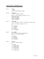
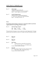
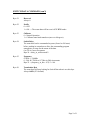
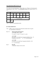
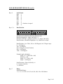
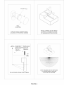
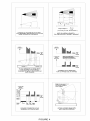
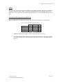
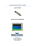
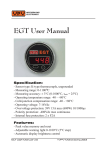
1
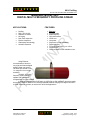
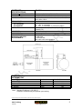
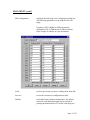
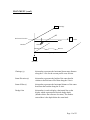
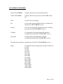
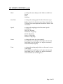
881L Imaging
445-039 JANUARY 2006-REVISED SEPTEMBER 2011
IMAGENEX MODEL 881L
DIGITAL MULTI-FREQUENCY IMAGING SONAR
APPLICATIONS:
•
•
•
•
•
•
•
•
•
ROV, AUV, & UUV
Offshore Oil & Gas
Sunken Timber Recovery
Diving Support
Surveying
Search & Recovery
Inspection
Underwater Archaeology
Scientific Research
FEATURES:
•
•
•
•
•
•
•
•
•
•
•
Ethernet
Programmable
Multi-frequency
High performance
Lower cost
Low power
Simple set-up and installation
Digital telemetry
Full scale range from 1 m to 200 m
Compact size
Communication format available to user
Using Ethernet communications, this all-inone, high performance digital imaging sonar can
exceed 100 shots per second on the 1 m range at a
2 mm range resolution, producing near-photographic
image quality.
The 881L is a multi-frequency system that
can operate with customized configurations or revert
to default settings to match appropriate operating
range scales.
In addition to the benefits of low power, a
simple set-up and installation procedure make this
powerful sonar an ideal tool for remotely operated
platforms ranging from large work ROV’s to small
inspection vehicles, as well as AUV and UUV
applications.
Specifications subject to
change without notice
www.imagenex.com
Copyright © 2006 - 2013
Imagenex Technology Corp.
HARDWARE
SPECIFICATIONS:
FREQUENCY
TRANSDUCER
TRANSDUCER BEAM WIDTH
RANGE RESOLUTION
MIN. DETECTABLE RANGE
MAX. OPERATING DEPTH
MAX. CABLE LENGTH
INTERFACE
CONNECTOR
POWER SUPPLY
DIMENSIONS (for both depths)
WEIGHT: In Air
In Water
MATERIALS
FINISH
310 kHz, 675 kHz, or 1 MHz (standard default settings)
-Other frequencies can be selected through programmable
software configurations
(Tunable from 280 kHz to 1.1 MHz in 5 kHz steps)
Imaging type, fluid compensated
310 kHz: 4° x 40°
675 kHz: 1.8° x 20°
1 MHz: 0.9° x 10°
1 m – 4 m: 2 mm (0.08”)
5 m & up: 10 mm (0.4”)
150 mm (6”)
1000 m and
3000 m available
Standard: 100 m on CAT5e
Cable length may be increased up to ~9000 m using an
Ethernet extender. Please enquire for more information.
Standard: 10 Mbps Ethernet (10 BASE-T) using TCP/IP
Bit rate may vary if an Ethernet extender is in use.
Side mounted, eight conductor, wet mateable
(Subconn MCBH-8M-SS)
Optional right angle or end mount connector
20 – 32 VDC at less than 5 Watts
79.4 mm (3.125”) diameter x 182 mm (7.125”) length
1000 m unit: 1.5 kg (3.3 lbs)
3000 m unit: 2 kg (4.4 lbs)
1000 m unit:
3000 m unit:
1000 m unit:
3000 m unit:
0.6 kg (1.3 lbs)
1.1 kg (2.4 lbs)
6061-T6 Aluminum & Polyurethane
Titanium, Polyurethane & 300 series stainless
steel
Hard Anodize
2
881L Imaging
445-039
www.imagenex.com
SOFTWARE
SPECIFICATIONS:
Win881L.exe
WINDOWS™ OPERATING SYSTEM
MODES
RANGE SCALES
Windows™ 95, 98, Me, NT, 2000, XP
Sector, Polar and Side Scan
1 m, 2 m, 3 m, 4 m, 5 m, 10 m, 20 m, 30 m, 40 m,
50 m, 60 m, 80 m, 100 m, 150 m, 200 m
Continuous rotation, 3° increments
TRAIN ANGLES
SECTOR SIZE:
SECTOR MODE
POLAR MODE
STEP SIZES
GRID TYPES
FILE FORMAT
RECOMMENDED
MINIMUM COMPUTER
REQUIREMENTS:
0° – 180°, 3° increments
0° – 357°, 3° increments, or Continuous rotation
Slow (0.3°), Medium (0.6°), Fast (0.9°), Faster (1.2°),
Fastest (2.4°)
Polar and rectangular
(filename).81L
100 MHz Pentium
16 MB RAM
1 GB Hard Disk
800 x 600 x 256 colour graphics
ORDERING
INFORMATION:
1000 m UNIT
3000 m UNIT
End mount connector
Right angle connector
IP Address*
Standard
Standard
Option
Option
Option
881-000-500
881-000-501
-009
-010
-020
*Note: Standard IP Address is 192.168.0.5
A different IP Address may be specified upon ordering.
Product and company names listed are trademarks or trade names of their respective companies.
3
881L Imaging
445-039
www.imagenex.com
881L Profiling
445-045 JUNE 2006-REVISED SEPTEMBER 2011
IMAGENEX MODEL 881L
DIGITAL MULTI-FREQUENCY PROFILING SONAR
APPLICATIONS:
•
•
•
•
•
•
•
•
Profiling
ROV, AUV & UUV
Offshore Oil & Gas
Surveying
Dam Face Inspection
Pipeline Inspection
Underwater Archaeology
Scientific Research
FEATURES:
•
•
•
•
•
•
•
•
•
•
•
Ethernet
Programmable
Multi-frequency
High performance
Lower cost
Low power
Simple set-up and installation
Digital telemetry
Full scale range from 1 m to 100 m
Compact size
Communication format available to user
Using Ethernet
communications, this all-inone, high performance digital
profiling sonar can exceed
100 shots per second on the
1 m range at a 2 mm range
resolution.
The 881L is a multifrequency system that can
operate with customized
configurations or revert to default settings to match appropriate operating range scales.
In addition to the benefits of low power, a simple set-up and installation procedure make
this powerful sonar an ideal tool for remotely operated platforms ranging from large work ROV’s
to small inspection vehicles, as well as AUV and UUV applications.
Specifications subject to
change without notice
www.imagenex.com
Copyright © 2006 - 2013
Imagenex Technology Corp.
HARDWARE
SPECIFICATIONS:
FREQUENCY
TRANSDUCER
TRANSDUCER BEAM WIDTH
RANGE RESOLUTION
MIN. DETECTABLE RANGE
MAX. OPERATING DEPTH
MAX. CABLE LENGTH
INTERFACE
CONNECTOR
POWER SUPPLY
DIMENSIONS
(for both depth ratings)
WEIGHT: In Air
In Water
MATERIALS
FINISH
675 kHz
-Other frequencies can be selected through programmable
software configurations
(Tunable from 600 kHz to 1 MHz in 5 kHz steps)
Profiling type, fluid compensated
600 kHz: 2.4°
675 kHz: 2.1°
1 MHz: 1.4°
1 m – 4 m: 2 mm (0.08”)
5 m & up: 10 mm (0.4”)
150 mm (6”)
1000 m and
3000m available
Standard: 100 m on CAT5e
Cable length may be increased up to ~9000 m using an
Ethernet extender. Please enquire for more information.
Standard: 10 Mbps Ethernet (10 BASE-T) using TCP/IP
Bit rate may vary if an Ethernet extender is in use.
Side mounted, eight conductor, wet mateable
(Subconn MCBH-8M-SS)
Optional right angle or end mount connector
20 – 32 VDC at less than 5 Watts
79.4 mm (3.125”) diameter x
234mm (9.2”) length
1000 m unit: 1.8 kg (4 lbs)
3000 m unit: 2.2 kg (4.8 lbs)
1000 m unit:
3000 m unit:
1000 m unit:
3000 m unit:
0.6 kg (1.3 lbs)
1 kg (2.2 lbs)
6061-T6 Aluminum & Polyurethane
Titanium, Polyurethane & 300 series stainless
steel
Hard Anodize
2
881L Profiling
445-045
www.imagenex.com
SOFTWARE
SPECIFICATIONS:
Win881L.exe
WINDOWS™ OPERATING SYSTEM
MODES
RANGE SCALES
Windows™ 95, 98, Me, NT, 2000, XP
Side Scan, Polar, and Sector
1 m, 2 m, 3 m, 4 m, 5 m, 10 m, 20 m, 30 m, 40 m, 50 m,
60 m, 80 m, 100 m
Continuous rotation, 3° increments
TRAIN ANGLES
SECTOR SIZE:
SECTOR MODE
POLAR MODE
STEP SIZES
GRID TYPES
FILE FORMAT
RECOMMENDED
MINIMUM COMPUTER
REQUIREMENTS:
0° – 180°, 3° increments
0° – 357°, 3° increments, or Continuous rotation
Slow (0.3°), Medium (0.6°), Fast (0.9°), Faster (1.2°),
Fastest (2.4°)
Polar and rectangular
(filename).81L
100 MHz Pentium
16 MB RAM
1 GB Hard Disk
800 x 600 x 256 colour graphics
ORDERING
INFORMATION:
1000 m UNIT
3000 m UNIT
End mount connector
Right angle connector
IP Address*
Standard
Standard
Option
Option
Option
881-000-520
881-000-521
-009
-010
-020
*Note: Standard IP Address is 192.168.0.5
A different IP Address may be specified upon ordering.
Product and company names listed are trademarks or trade names of their respective companies.
3
881L Profiling
445-045
www.imagenex.com
10
8
9
7
6
4
5
3
1
2
RJ-45 Connector
H
H
SUBCONN MCIL8F
(F)
Wired as “568B”
2
G
8
1
3
4
1
3
6
8
G
7
6
5
F
2
ORG/WHT
(TD+)
ORG
(TD-)
GRN
(RX-)
GRN/WHT
(RX+)
F
Socket View
2ft #18
SUBCONN MCIL8F
(F)
E
E
-VIN
TX+
+VIN
TX-
D
RX+
C
BLK
1
WHT
2
RED
3
GRN
4
ORG
5
RX-
6
N/C
7
N/C
8
BLU
WHT/BLK
/
/
/
//
/
/
/ N/C
RED/BLK
BLK
BLK #18
/
/
/
//
/
/
/
WHT
RED
GRN
BRN
BLU
-VIN
RED #18
GRN/WHT
GRN
ORG/WHT
ORG
+VIN
3
RX+
6
RX-
1
TD+
2
TD-
D
N/C
C
2ft
50ft
5ft
2ft Whip
6 Conductor Cable
CAT.5e UTP
Ethernet Cable
B
B
IMAGENEX TECHNOLOGY CORP.
Title:
A
Model 881L Test Cable
Document Number:
Date:
10
9
8
7
6
5
4
3
Jan 11, 2006
2
Rev
01
881-200-187
Sheet
1
1
of
1
A
10
H
7
6
4
5
3
RJ-45 Connector
H
8
1
3
4
1
2
SUBCONN MCIL8F
(F)
2
G
8
9
Wired as “568B”
7
1
2
3
6
8
G
6
5
Socket View
F
-VIN
E
2
+VIN
3
SUBCONN MCIL8F
(F)
D
TX-
4
RX+
5
RX-
6
TG+
7
TG-
2ft
50ft
BLK
1
TX+
2ft Whip
CAT 5e.
Cable
WHT
RED
GRN
ORG
BLU
WHT/BLK
RED/BLK
8
//
//
//
//
//
//
//
//
BRN
GRN / WHT
BLU
GRN
ORG / WHT
ORG
BLU / WHT
BRN / WHT
ORG/WHT
(TD+)
ORG
(TD-)
GRN/WHT
(RX+)
GRN
(RX-)
F
2ft
BLK
//
//
//
//
//
//
//
//
-VIN
RED
E
+VIN
GRN/WHT
GRN
ORG/WHT
ORG
3
RX+
6
RX-
1
TD+
2
TD-
RJ45
5ft
CAT.5e UTP
Ethernet Cable
D
VIO
TRIGGER + (TG+)
GRY
TRIGGER - (TG-)
C
C
EXTERNAL TRIGGER
B
B
TG+
5V
TG-
0V
IMAGENEX TECHNOLOGY CORP.
881L Test Cable With External Trigger
Rev
Document Number: 881-200-209
00
Feb 09, 2007
Date:
Sheet 1 of 1
Title:
A
TTL Pulse - Minimum of 100μs long
10
9
8
7
6
5
4
3
2
1
A
IMAGENEX TECHNOLOGY CORP.
12MAR07
MODEL 881L ETHERNET SONAR HEAD (Multi-Frequency)
WIN881L.EXE
c/w External Trigger Option
Special Notes:
Refer to Imagenex Drawing Number 881-200-209 for External Trigger information
To enable the 881L sonar head for external trigger mode, the Win881L.INI configuration
file provides the following control:
[Settings]
ExternalTriggerControl
Bit 0: Trigger Edge: 0 = NEG, 1 = POS
Bit 1: Enable: 0 = Disable, 1 = Enable
When enabled for external trigger, the sonar head will transmit as soon as it detects the
external trigger pulse. If a trigger pulse has not been found after a period of 2 seconds,
the sonar will transmit as normal.
IMAGENEX TECHNOLOGY CORP.
19JAN09
MODEL 881L ETHERNET SONAR HEAD (Multi-Frequency)
WIN881L.EXE: Display Software For Win 95/98/Me/NT/2000/XP
VERSION 1.04
OVERVIEW
WIN881L is a Windows 95/98/Me/NT/2000/XP program that controls, displays and
records data from the multi-frequency Model 881L Ethernet Sonar Head. The program
communicates with the sonar head via a 10 Mbps Ethernet connection and uses an RS232 COM port at 4800,N,8,1 for receiving GPS Lat/Lng coordinates. The head can be
operated at different ranges, gains, speeds, frequencies, etc. The Windows display mode
must be at least 800 x 600 pixels with small fonts selected.
SCREEN LAYOUT
The main screen of WIN881L comprises of a sonar data window on the left side with
various sonar head controls and a sector size icon on the right side. Other items include
an operating frequency display, a x2 Pixel Zoom window, date/time readout, Lat/Lng
readout, sonar head range/bearing readout to one or two cursors and a control for
displaying real time data from the head or playback data from a file. A Pop-up window is
available for displaying sonar head diagnostics.
OPERATION
To operate the sonar head, connect the RJ45 ethernet connector from the sonar head
cable into the LAN (Local Area Network) card on your PC. The sonar head needs to run
with a static IP (Internet Protocol) Address for both head and PC. The IP Address of the
PC must be set to 192.168.0.X where X is any number between 6 and 255. Also set the
subnet mask to 255.255.255.0. In Windows XP, these settings can be found in the
‘Network Connections’ menu under ‘Settings’ in the ‘Start’ menu, then click on
properties of the LAN adapter, and properties of the TCP/IP. There is also a settings box
for default gateway, but it can be left blank. The IP Address of the sonar head is fixed at
192.168.0.5 (optional IP Address’s can be specified at time of order). Apply 20 to
36VDC to the sonar head power wires (+V to RED, -V to BLACK) using a DC power
supply capable of supplying a current of 0.5 Amps. Run the program WIN881L.EXE and
select the button DATA FROM 'HEAD' on the right-hand side of the display.
Page 1 of 23
MAIN MENU
File Menu
Record Start (Stop)...
opens a File Name Dialog Box so the user can input a
filename for logging sonar data (shot by shot) complete
with timestamp. The file extension is always '.81L'. The
filename and current size (kbytes) of the file are displayed
at the top of the screen. File recording continues until
Record Stop is selected. Available only when DATA
FROM 'HEAD' is active.
Playback...
opens a File Name Dialog Box so the user can select and
playback a previously recorded '.81L' Sonar file.
Available only when DATA FROM 'FILE' is active.
Copy Start (Stop)...
opens a File Name Dialog Box so the user can enter a
filename for a new ‘.81L’ file that can be used for making
smaller data files from large pre-recorded sonar files. The
filename and current size (kbytes) of the file are displayed
at the top of the screen. File copying continues until Copy
Stop is selected. Available when DATA FROM 'FILE' is
active.
Save Screen...
opens a File Name Dialog Box so the user can enter a
filename for saving the screen as a '.BMP' Windows
Bitmap file
Auto Frame Capture
allows the user to automatically create screen captures for
time-lapsed movie file creation. Whenever there is is scan
direction change or whenever the sonar scans a full 360
degrees, a '.BMP' file of the screen is automatically
generated. An incrementing number is appended to the
filename for each successive screen capture, the format is
“filename-nnnn.bmp”. Select ‘Auto Frame Capture
Start…’ to begin the capture process, then select ‘Auto
from Capture Stop…’ to finish. Available when DATA
FROM 'FILE' is active.
Exit
writes current configuration to file (WIN881L.INI),
closes the program and exits to Windows.
Page 2 of 23
MAIN MENU (con't)
Color Table Menu
Norm Hi
Norm Lo
Green
Grey
Rev Grey
Brown/Yellow
Green/Blue
Green/Yellow
Blue
normal high intensity color table used for mapping the
echo data amplitude to a color for display. Color depth is
107 colors ranging from Black (low level) through Blue,
Green, Orange, Yellow, White and Red (max level).
normal low intensity color table.
107 shades of green.
107 shades of grey (White on Black).
107 shades of grey (Black on White).
107 mixed shades of brown and yellow.
107 mixed shades of green and blue.
107 mixed shades of green and yellow.
107 shades of blue.
Options Menu
Units
to change the units of measurement from Meters to Feet.
Xdcr Position
to adjust the display of the sonar echo data relative to the
physical mounting of the sonar head. If the xdcr
(transducer) is physically mounted down (red side down),
this switch should be set to 'Down'. If the xdcr is mounted
up (red side up), 'Up' should be selected. If this switch is
set incorrectly, the sonar display will appear as a mirror
image; targets which are actually on the right side will
appear on the left, and vice-versa. If Profile Grid is
enabled via the Profile Menu, the Xdcr Position names
change to ‘Fwd’ and ‘Aft’ for profiling applications.
Sound Velocity
to change the speed of sound number used in range
measurements. This number can have a range of 750 m/s
(2461 ft/s) to 2250 m/s (7381 ft/s). The default is 1500
m/s (4921.3 ft/s).
User Text
to enter a text string for display in the User Text Window.
Calibrate Sonar Head
to re-calibrate the sonar head transducer to the center
position.
Page 3 of 23
MAIN MENU (con't)
Com Ports Menu
GPS Input
to select the serial communications port (COM1-COM32)
for receiving Lat/Lng ships position coordinates from a
GPS receiver. This port accepts the NMEA 0183
$GPGLL string or the $GPGGA string at 4800,N,8,1.
Enable
select to initialize the serial communications port for
reception of Lat/Lng coordinates
Disable
to close the serial communications port
GLL
to use Lat/Lng coordinates from the $GPGLL string
GGA
to use Lat/Lng coordinates from the $GPGGA string
Page 4 of 23
MAIN MENU (con't)
MULTI-FREQUENCY OPERATION
The default configuration for Win881L automatically adjusts the operating frequency,
absorption and pulse length with range. The following Table describes this relationship:
Range
(m)
Frequency
(kHz)
Absorption
(dB/m)
1
2
3
4
5
10
20
30
40
50
60
80
100
150
200
1000
1000
1000
1000
1000
675
675
675
675
675
675
675
675
310
310
0.6
0.6
0.6
0.6
0.6
0.2
0.2
0.2
0.2
0.2
0.2
0.2
0.2
0.1
0.1
Pulse Length
(μs)
Polar Mode
20
20
20
20
60
60
100
160
220
260
320
420
540
800
1000
Pulse Length
(μs)
Sector/Sidescan
10
10
10
10
30
30
50
80
110
130
160
210
270
400
530
The frequencies in the above table are designed for use with
the Fan Beam Imaging Sonar (Model 881-000-500/501) only!
The Pencil Beam Profiling Sonar (Model 881-000-520/521)
has a frequency limit of 600 kHz to 1 MHz.
Page 5 of 23
MAIN MENU (con't)
Settings Menu
Allows the user to manually or automatically adjust the sonar head’s operating
frequency, absorption and pulse length.
Manual Frequency Setup
select Enable to adjust the following parameters for
the current range:
Frequency (280-1100kHz in 5kHz increments)
Absorption (0.01-2.55dB/m in 0.01 dB increments)
Pulse Length (10-1000μs in 10μs increments)
Auto Frequency Setup
select Enable to use the pre-programmed
frequencies, absorptions and pulse lengths from the
displayed Current Configuration.
Page 6 of 23
MAIN MENU (con't)
Edit Configuration
to display the following User Configuration dialog box.
The following parameters can be modified for each
range:
Frequency (280-1100kHz in 5kHz increments)
Absorption (0.01-2.55dB/m in 0.01 dB increments)
Pulse Length (10-1000μs in 10μs increments)
Load…
to load a previously saved user configuration from disk.
Save As…
to save the current user configuration to disk.
Default
to load the factory default configuration. The default
values for each individual range can be selected by
pressing the button labeled ‘D’ beside each range row.
Page 7 of 23
MAIN MENU (con't)
Misc Menu
Pixel Zoom (x2)
displays a x2 pixel zoom window in the lower right
hand corner of the screen. A rectangular area about
the cursor is displayed in this window. If the left
mouse button is pressed anywhere in the sonar
image window, the zoom window will be captured
(held). Pressing the button a second time releases
the capture.
Clear Screen Now
to clear all echo data from the sonar display.
Diagnostics
displays the Diagnostics Pop-Up Window. This
window displays the header information from the
connected sonar head.
Page 8 of 23
MAIN MENU (con't)
Profile Menu
Profile Mode
to set the mode of operation for the display of the
digitized profile range points. The following modes are
available:
Off
No profile range point is plotted, echo data is plotted
normally.
Points Only
Only the profile range points are plotted, no echo data is
sent from the head.
Low Mix
The profile range point is plotted along with the echo
data. The echo data is plotted at 1/4 level so the profile
point stands out. This mode can be useful for making
Start Gain adjustments to optimize the profile points
before switching to Points Only mode.
Med Mix
Same as Low Mix but the echo data is plotted at 1/2 level.
High Mix
Same as Low Mix but the echo data is plotted at full level.
Profile Grid
to display a rectangular grid for profiling applications.
Zero Down
to enable plotting of profile data with the zero reference
of the sonar head pointing down rather than pointing up.
This allows plotting the seafloor in its correct orientation.
This item is available only if Profile Grid is enabled.
Page 9 of 23
MAIN MENU (con't)
Profile Setup…
allows the user to alter the detection scheme used to
generate the digitized profile range points.
Digitization Source
the profile range point for each ping is digitized in the
sonar head and sent to the surface in the 12 byte header.
The data is sampled with a resolution of 2mm for the 1, 2,
3 and 4 meter operating ranges. All other operating ranges
have a 10mm sampling resolution. The surface detection
resolution is Operating Range/500. You could select
‘Surface’ if you would like to alter the profile points
during playback (and record to a new file using the Copy
Start… function).
Detection Type
use Start of Pulse to display the profile points at the
beginning of the echo pulse. Use Center of Pulse to
display the profile point in the middle of the pulse. The
Detection Type can only be changed when Surface
Detection is used as the Sonar Head always uses Center
of Pulse detection.
Minimum Range
used to set the starting range for profile digitization.
Ranges less than this setting will not be digitized. The
minimum range can be adjusted from 0 to 25 meters in
0.1 meter increments.
Minimum Level
used to set the detection level for profile digitization. This
level can be adjusted from 10 to 90 percent of the color
scale. Levels less than this setting will not be digitized.
The Minimum Level can only be changed when Surface
Detection is used as the Sonar Head uses its own internal
level threshold.
Auto-Profile…
allows the user to automatically command the sonar to do
a scan and save the digitized profile points including
offsets to two different files. The first file is an ASCII file
with XYZ coordinates. The second is a screen capture to a
Windows bitmap file. The scan limits are based on the
current angles set via the Sector and Train switches and a
new ASCII file and screen capture are automatically
generated for each new scan.
Page 10 of 23
MAIN MENU (con't)
Y
Chainage
Reference Elevation
X
Offset
Water
Sonar
Baseline
Bottom
Dredge Depth
Z
Elevation
Chainage (y)
this number represents the horizontal down range distance
along the Y-Axis for the current profile cross-section.
Sonar Elevation (z)
this number represents the height of the sonar head in
relation to the Reference Elevation along the Z-Axis.
Sonar Offset (x)
this number represents the horizontal distance of the sonar
head from the baseline along the X-Axis.
Dredge Line
this number is used to display a horizontal line on the
display which represents the desired dredge depth
(distance below the reference elevation). The number
entered here is the depth below the sonar head.
Page 11 of 23
MAIN MENU (con't)
Auto-Profile Enable
when the Auto-Profile Enable is checked, pressing the Ok
button will invoke 1 scan using the current sonar settings
(i.e. range, gain, sector size, train angle, sound velocity).
The sonar will automatically move to its’ counterclockwise position and begin scanning. When the sonar
reaches its’ clockwise position, the following will occur:
A message box appears asking if you would like to save
the current profile. If you select Yes, a screen capture is
made and an ASCII XYZ file is generated for the current
scan with the profile points adjusted by the above x, y and
z offsets. The Auto-Profile Dialog Box is then displayed
allowing you to change the offset numbers for the next
scan. When you want to stop the Auto-Profile scanning,
simply disable the Auto-Profile Enable check box and
press Ok. You can invoke the Auto-Profile Dialog Box at
any time during a scan. When this dialog box is active,
the sonar head is put on hold until the Ok button is
pressed.
It is recommended that you record all data to a .81A file
via the Record Start… function in the File menu as the
XYZ ASCII file can not be displayed via this program.
After each scan…
you can customize the scanning process by enabling or
disabling the XYZ and BMP file generation. You can also
omit the save scan confirmation and Auto-Profile Dialog
Box display in order to gain hands-free operation.
The automatic filenames used for the ASCII file and the screen capture file are based
on the current system date:
DDMMMYYYY-nnnn.BMP
DDMMMYYYY-nnnn.XYZ
DD = day (1-31), MMM = month (Jan, Feb, Mar…), YYYY = year
nnnn (0001-9999), this number automatically increments for each new file (each new
scan).
Page 12 of 23
MAIN MENU (con't)
The XYZ ASCII file contains the following information:
YYYY.YY,M<CR><LF> - Chainage, M=meters, F=feet
ZZZZ.ZZ<CR><LF> - Sonar Elevation
XXXX.XX<CR><LF> - Sonar ‘X’ Offset
VVVV.VV<CR><LF> - Sound Velocity
dd-mmm-yyyy hh:mm:ss.hh rrr.rrr aaa.aaa bbb.bbb
dd-mmm-yyyy hh:mm:ss.hh rrr.rrr aaa.aaa bbb.bbb
.
.
dd-mmm-yyyy hh:mm:ss.hh rrr.rrr aaa.aaa bbb.bbb
xxx.xxx yyy.yyy
xxx.xxx yyy.yyy
zzz.zzz<CR><LF> - 1st Point
zzz.zzz<CR><LF> - 2nd Point
xxx.xxx yyy.yyy
zzz.zzz<CR><LF> - Last Point
where:
dd-mmm-yyyy = current system date
hh:mm:ss.hh = current system time
rrr.rrr = profile range
aaa.aaa = 0 (not used)
bbb.bbb = vertical scanning angle
xxx.xxx = sonar_offset + profile_range * sin (vertical angle)
yyy.yyy = chainage
zzz.zzz = sonar_elevation – profile_range * cos(vertical angle)
The above fields are TAB delimited.
The Chainage, Sonar Elevation, Sonar Offset and Dredge Line numbers are saved in
the WIN881A.INI file but are not saved in the .81A data files. The Auto-Profile
function is available only when DATA FROM 'HEAD' is active.
Page 13 of 23
MAIN MENU (con't)
Grid Menu
Grid On/Off
to display the range rings on the sonar display.
About Menu
About WIN881L
displays an about box showing the software version and
date of this program. Contact information for Imagenex
Technology Corp. is also displayed.
Page 14 of 23
ON SCREEN SWITCHES
DATA FROM 'HEAD'
to display data from the connected sonar head.
DATA FROM 'FILE'
to display data from a previously recorded '.81L' Sonar
file.
Hold
to hold or freeze the display.
Rev
to reverse the current scanning direction. Available only
when DATA FROM 'HEAD' is active.
Reverse
to reverse the file playback plotting direction. Available
only when DATA FROM 'FILE' is active.
TrackBar
to re-position the file pointer during file playback.
Available only when DATA FROM 'FILE' is active.
Plot Speed
to adjust plotting speed during file playback.
Available only when DATA FROM 'FILE' is active.
The following switches are available only when DATA FROM 'HEAD' is active:
Range
to change the sonar operating range. Ranges available are:
1m (3ft)
2m (6ft)
3m (9ft)
4m (12ft)
5m (15ft)
10m (30ft)
20m (60ft)
30m (90ft)
40m (120ft)
50m (150ft)
60m (180ft)
80m (240ft)
100m (300ft)
150m (450ft)
200m (600ft)
Page 15 of 23
ON SCREEN SWITCHES (con’t)
Mode
to change the sonar display mode. Modes available are:
Sector
Polar
SideScan
Start Gain
to change the starting gain of the head. Increase to get
higher return levels, decrease to get lower return levels.
The Start Gain can be adjusted from 0dB to 40dB in 1dB
increments.
Speed
to change the stepping speed of the sonar. Speeds
available are:
Slow (0.3 deg/step)
Medium (0.6 deg/step)
Fast (0.9 deg/step)
Faster (1.2 deg/step)
Fastest (2.4 deg/step)
Sector
to change the sector size (sweep angle).
Sector Mode (0 to 180 degrees in 3 degree increments)
Polar Mode (0 to 360 degrees in 3 degree increments)
Sidescan Mode(0 degrees)
Train
to change the training angle relative to the sonar's zero or
center angle.
Sector Mode (0 to 357 degrees in 3 degree increments)
Polar Mode (0 to 357 degrees in 3 degree increments)
Sidescan Mode (90 or 270 degrees)
Page 16 of 23
KEYBOARD SWITCHES
The following switches are selected via keyboard entry (case insensitive):
C
to clear the sonar screen display.
G
to change the Start Gain of the sonar head. When the 'G'
key is pressed, the Key Command Entry Box displays the
prompt: Gain: ? dB. Type in a valid start gain number (040dB) and press <Enter> to change to the new start gain
value. If the entered gain is not valid or the <Esc> key is
pressed, the current gain will be used. Available only
when DATA FROM 'HEAD' is active.
H
to hold or freeze the display.
R
to change the operating range of the sonar head. When the
'R' key is pressed, the Key Command Entry Box (below
the DATA FROM buttons) is displayed with the
following prompt: Range: ? M (meters) or Range: ? FT
(feet). Type in a valid range number: 1(3), 2(6), 3(9),
4(12), 5(15), 10(30), 20(60), 30(90), 40(120), 50(150),
60(180), 80(240), 100(300), 150(450) or 200(600) in
meters or (feet) using the numeric keys and then press
<Enter> to change to the new range. If the entered range
is not valid or the <Esc> key is pressed, the current range
will be used. Available only when DATA FROM 'HEAD'
is active.
Space Bar
to reverse the current scanning direction. Can also be used
to reverse the file playback direction.
Page 17 of 23
ONE CURSOR MEASUREMENT
One Cursor Measurement is used for measuring the distance and relative bearing to a
target with respect to the transducer origin. When the mouse is moved into the sonar
image display area, the cursor changes from an arrow to a square target cursor. The range
and bearing to the target cursor is displayed in the Range/Bearing Display Box
underneath the sonar image display. The area about the target cursor is also displayed in
the Pixel Zoom window. Clicking the left mouse button while the cursor is in the sonar
image display area captures (freezes) the zoom window image. Clicking the left button a
second time allows normal zoom window updating.
TWO CURSOR MEASUREMENT
Two Cursor Measurement is used for measuring the distance and relative bearing
between two targets. To invoke two cursor measurement, position the mouse cursor over
a target in the sonar image display area and press the right mouse button. A target origin
cursor is placed at this location. The range and bearing to this cursor becomes the new
origin for future measurements. When the mouse is moved, a rubber banded line is drawn
from the target origin cursor to the target cursor. The Range/Bearing Display Box shows
the range and bearing to the new origin (Org), the range and bearing to the target cursor
(Tar) and the range and bearing difference (Diff) between the two cursors. The displayed
range and bearing between the two cursors is always relative to the target origin cursor.
Press the right mouse button again to return to One Cursor Measurement.
MESSAGES
No Connection
- no power to the sonar head
- cable not connected
- IPAddress_Sonar1 setting in the WIN881L.INI file
is not the same as the sonar head IP Address
GPS Lat/Lng Not Available
- GPS receiver output not connected to serial port
- GPS receiver is not sending data
- GPS receiver not set for 4800,N,8,1
- GPS Input COM port set to the wrong port number
- GPS receiver not sending $GPGLL or $GPGGA
Page 18 of 23
DATA STORAGE FILE FORMAT (.81L)
When recording the sonar data to a .81L file, the following bytes are appended and saved
to the file every 'shot':
Byte #
0 to 99
100 to 111
112 to xxxx
xxxx+1
to yyyy
yyyy+1
to zzzz
N-1
N-2
Description
File Header (100 Bytes)
Sonar Return Data Header (12 Bytes)
Sonar Return Echo Data
(0, 128, 250, 252 or 500 Bytes)
xxxx = 112+above number
Byte xxxx always = 0xFC (Termination Byte from sonar head)
Zero Fill
yyyy = 127, 255, 383 or 639
Extended Bytes
If Byte #34 (in the File Header) is greater than zero, multiply Byte #34
by 128 to derive the number of Extended Bytes for this shot.
i.e. if Byte #34 = 0x01, Extended Bytes = 128
zzzz = yyyy+Number of Extended Bytes
Pointer To Previous Shot
The last 2 bytes of this shot contain a 16-Bit number that is the sum of
the number of bytes for this shot and the number of bytes for the
previous shot. This number is used for reverse playback
synchronization.
N = (128 or 256 or 384 or 640) + Extended Bytes
Number of bytes to previos shot = ((N-2)<<8) | (N-1)
FILE HEADER
Bytes 0 through 99 contain the following File Header information:
0
1
2
ASCII '8'
ASCII '1'
ASCII 'L'
3
nToReadIndex - Index for Number of Data Bytes
0 = 0 Data Bytes
1 = 128 Data Bytes
2 = 250 or 252 Data Bytes
3 = 500 Data Bytes
Page 19 of 23
DATA STORAGE FILE FORMAT (.81L) (con't)
4-5
Total Bytes - number of bytes that are written to the disk for this shot
7
6-7
6
5
Byte 4
4 3
Byte 5
2 1 0 7 6 5 4 3
128, 256, 384 or 640
+ Number of Extended Bytes
2
1
0
2
1
0
nToRead - Number of Bytes from the sonar head
7
6
5
Byte 6
4 3
2 1 0 7 6 5
13, 141, 263, 265 or 513
Byte 7
4 3
8-19
Date - null terminated date string (12 bytes)
"DD-MMM-YYYY"
20-28
Time - null terminated time string (9 bytes)
"HH:MM:SS"
29-32
Hundredth of Seconds - null terminated string (4 bytes)
".hh"
33-36
Reserved - always 0
37
Dir, Xdcr, Mode, Step
7
Dir
0=ccw
1=cw
6
Xdcr
0=Dn
1=Up
5
Byte 37
4
3
Mode
0 = Sector
1 = Polar
2 = Sidescan
2
1
0
Step Size
0 = 0.3 Deg (Slow)
1 = 0.6 Deg (Medium)
2 = 0.9 Deg (Fast)
3 = 1.2 Deg (Faster)
4 = 2.4 Deg (Fastest)
38
Start Gain
0 to 40 in 1 dB increments
39
(Sector Size)/3
0 to 120 = 0 to 360 Degrees in 3 degree increments
40
(Train Angle)/3
0 to 119 = 0 to 357 Degrees in 3 degree increments
Page 20 of 23
DATA STORAGE FILE FORMAT (.81L) (con't)
41
Reserved - always 0
42
Absorption
1 to 255 = 0.01 to 2.55dB/m in 0.01dB/m increments
43
Profile Grid, Zero, Data Bits, LOGF
7
Profile
Grid
0=OFF
1=ON
6
Zero
0=Up
1=Dn
Byte 43
4
3
Data Bits
5
0 = 4 Data Bits
1 = 8 Data Bits
2 = 14 Data Bits
44
(Pulse Length)/10
0 to 100 = 0 to 1000μs in 10μs increments
45
Profile
0 = Off
1 = Points Only
2 = Low Mix
3 = Medium Mix
4 = High Mix
46-47
Sound Velocity
7
V
6
2
1
LOGF
0
0 = 10 dB
1 = 20 dB
2 = 30 dB
3 = 40 dB
Byte 46
Byte 47
5 4 3 2 1 0 7 6 5 4 3 2
Sound Velocity (in meters/second) * 10
1
0
If 'V' = 0, Sound Velocity = 1500.0 m/s
If 'V' = 1, Sound Velocity = [((Byte 46 & 0x7F)<<8) | (Byte 47)]/10.0
48-79
User Text - null terminated text string (32 bytes)
80-81
Operating Frequency
7
82-99
6
5
Byte 80
Byte 81
4 3 2 1 0 7 6 5 4 3 2
Operating Frequency (in kHz)
1
0
Reserved - always 0
Page 21 of 23
DATA STORAGE FILE FORMAT (.81L) (con't)
SONAR RETURN DATA HEADER
SONAR RETURN ECHO DATA
ZERO FILL
The following bytes contain the Sonar Return Data that is acquired directly from the
Ethernet port:
If Header is ASCII 'IPX':
Bytes 100 through 112 (13 bytes)
Bytes 113 through 127 (15 bytes - Zero Fill)
If Header is ASCII 'IMX':
8-Bit
Bytes 100 through 364 (265 bytes)
Bytes 365 through 383 ( 19 bytes - Zero Fill)
If Header is ASCII 'IGX':
8-Bit
Bytes 100 through 612 (513 bytes)
Bytes 613 through 639 ( 27 bytes - Zero Fill)
Page 22 of 23
DATA STORAGE FILE FORMAT (.81A) (con't)
EXTENDED BYTES (starting at yyyy+1)
0-11
GPS Ships Position Latitude – null terminated text string (12 bytes)
“dd.mm.xxx_N”
dd = Degrees
mm = Minutes
xxx = Decimal Minutes
_ = Space
N = North or S = South
12-24
GPS Ships Position Longitude – null terminated text string (13 bytes)
“ddd.mm.xxx_E”
ddd = Degrees
mm = Minutes
xxx = Decimal Minutes
_ = Space
E = East or W = West
Page 23 of 23
IMAGENEX TECHNOLOGY CORP.
23JAN07
MODEL 881L DIGITAL SONAR HEAD (881-000-50x)
ETHERNET INTERFACE SPECIFICATION (v1.00)
OVERVIEW
The Model 881L Digital Sonar Head communicates over an Ethernet communications
link. To receive echo data, a command program must interrogate the sonar head by
sending a Switch Data Command. All Ethernet communications are via TCP/IP at
10Mbps. When the Switch Data command is accepted, the sonar head transmits, receives
and sends its return data back to the command program.
Unless otherwise specified, the 881L Sonar Head will have a statically assigned IP
Address of 192.168.0.5 .
SWITCH DATA COMMAND
The sonar head accepts 27 bytes of switch data from the command program and must see
the switch data header (2 bytes: 0xFE and 0x44 HEX) in order to process the switches.
The sonar head will stop accepting switch data when it sees the termination byte (0xFD
HEX). The termination byte must be present for the sonar to process the switches.
Byte #
0–7
8 – 15
16 – 23
24 – 26
Table 1
Head
0xFE 0x44
ID
Start
LOGF AbsorpGain
tion
External Reserved Reserved
Trigger
0
0
Switch
FreqTerm.
Delay
uency
0xFD
Description
Range Reserved
Rev/
Reserved Reserved
0
Hold
0
0
Train
Sector
Step
Pulse
Profile
Angle
Width
Size
Length MinRange
Data
Data
Reserved Profile Calibrate
Points
Bits
0
Model 881L Sonar Head Switch Data Command
Page 1 of 9
SWITCH DATA COMMAND (con't)
BYTE DESCRIPTIONS
Note: All Byte values are shown in decimal unless noted with a '0x' (hexadecimal) prefix.
Byte 0
Switch Data Header (1st Byte)
Always 0xFE (254 decimal)
Byte 1
Switch Data Header (2nd Byte)
Always 0x44 (68 decimal)
Byte 2
Head ID
Always 0x10
Byte 3
Range
1, 2, 3, 4, 5, 10, 20, 30, 40, 50, 60 ,80, 100, 150 and 200 Meters
Byte 4
Reserved
Always 0
Byte 5
Hold
Bit 0
Bit 1
Bit 2
Bit 3
Bit 4
Bit 5
Bit 6
Bit 7
- 1 = Hold (or pause) Head, 0 = Resume
-0
-0
-0
-0
-0
- 1 = Reverse Step Direction, 0 = Normal Operation
-0
Byte 6
Reserved
Always 0
Byte 7
Reserved
Always 0
Byte 8
Start Gain
0 to 40dB in 1dB increments
Page 2 of 9
SWITCH DATA COMMAND (con't)
Byte 9
LOGF
1 = 20dB
No other values available at this time.
Byte 10
Absorption
0 to 255 = 0.00dB/m to 2.55dB/m
Byte 10 = two way absorption_in_dB_per_m * 100
Recommended values:
330kHz: 10 (0.1dB/m)
675kHz: 20 (0.2dB/m)
1MHz: 60 (0.6dB/m)
Byte 11
Train Angle
0 to 120 (-180 Deg to +180 Deg = 360 Deg Total) in 3 Degree steps.
Byte 11 = (train_angle_in_degrees + 180)/3
i.e.
0 = -180 Degrees
30 = -90 Degrees
60 = 0 Degrees
90 = +90 Degrees
120 = +180 Degrees
Byte 12
Sector Width
0 to 120 (0 Deg to 360 Deg) in 3 Degree steps
Byte 12 = sector_width_in_degrees/3
i.e.
0 = 0 Degrees
30 = 90 Degrees
60 = 180 Degrees
120 = 360 Degrees
Byte 13
Step Size
0 to 8 in 0.3 Degree increments
i.e.
0 = No Step
1 = 0.3 Degrees/Step
2 = 0.6 Degrees/Step
3 = 0.9 Degrees/Step
4 = 1.2 Degrees/Step
8 = 2.4 Degrees/Step
Page 3 of 9
SWITCH DATA COMMAND (con't)
Byte 14
Pulse Length
Length of acoustic transmit pulse.
1-100 Æ 10 to 1000 μsec in 10 μsec increments
Byte 14 = pulse_length_in_microseconds/10
Byte 15
Profile Minimum Range
Minimum range for profile point digitization
0 – 250 Æ 0 to 25 meters in 0.1 meter increments
Byte 15 = min range in meters * 10
Note:
The following External Trigger Control byte is valid only for 881L Sonar Heads
supplied with the External Trigger Hardware Option.
Byte 16
External Trigger Control
Bit0: Edge: 0 = NEG,
Bit1: Enable: 0 = Disable,
1 = POS
1 = Enable
The sonar head will transmit as soon as it detects the external trigger pulse. If a trigger
pulse has not been found after a period of 2 seconds, the sonar will transmit as normal.
Byte 17
Reserved
Always 0
Byte 18
Reserved
Always 0
Byte 19
Data Points
50
- 500 data points are returned by the sonar head
The return data will have an ASCII 'IGX' header.
No other values available at this time.
Byte 20
Data Bits
Resolution (number of data bits) of the returned echo data
8
- Data width = 8 Bits, 1 data point per byte
No other values available at this time.
Page 4 of 9
SWITCH DATA COMMAND (con't)
Byte 21
Reserved
Always 0
Byte 22
Profile
0 = OFF
1 = ON --> The return data will have an ASCII 'IPX' header.
Byte 23
Calibrate
0 = Normal Operation
1 = Calibrate sonar head transducer (move to 0 degrees).
Byte 24
Switch Delay
The sonar head can be commanded to pause (from 0 to 500 msec)
before sending its return data to allow the commanding program
enough time to setup for the return of the data.
0 to 250 in 2 msec increments
Byte 24 = delay_in_milliseconds/2
Byte 25
Frequency
675kHz +/- 500kHz
0 – 200 Æ 175kHz to 1175khz in 5kHz increments
Byte 25 = (frequency_in_khz - 675)/5 + 100
Byte 26
Termination Byte
The sonar head will stop looking for Switch Data when it sees this byte.
Always 0xFD (253 decimal)
Page 5 of 9
SONAR HEAD RETURN DATA
Every shot, the sonar head returns a 12 Byte header, 0 or 500 bytes of echo data and a
terminating byte value of 0xFC. The total number of bytes (N) returned will be 13 or
513.
Byte #
0 to 5
6 to 11
Description
ASCII
ASCII
ASCII
Head
'I'
'G' or 'P'
'X'
ID
Reserved Range Prof Rng Prof Rng
0
(LO)
(HI)
12 to
(N-2)
N-1
Table 2
Serial
Status
Data
Bytes
(LO)
Reserved
0
Data
Bytes
(HI)
Echo Data
0 or 500 Data Bytes
Term.
0xFC
Model 881L Sonar Head Return Data
BYTE DESCRIPTIONS
Note: All Byte values are shown in decimal unless noted with a '0x' prefix.
N = total number of return bytes
Byte 0 - 2
Imagenex Return Data Header
ASCII 'IMX', 'IGX' or 'IPX'
'I' = 0x49, 'G' = 0x47, 'P' = 0x50, 'X' = 0x58
ASCII 'IGX'
In response to a Switch Data Command with Data Points = 50
If Data Bits was set to 8:
N = 513, (500 Data Bytes)
ASCII 'IPX'
In response to a Switch Data Command with Profile = ON
N = 13, (0 Data Bytes)
Byte 3
Head ID
16 Head ID’s allowed: 0x10 to 0x1F
Page 6 of 9
SONAR HEAD RETURN DATA (con't)
Byte 4
Serial Status
Bit 0 - 1
Bit 1 - 0
Bit 2 - 0
Bit 3 - 0
Bit 4 - 0
Bit 5 - 0
Bit 6 - 1 = Switches Accepted
Bit 7 - 0
Byte 5 - 6
Head Position
7
0
6
5
Byte 5
4 3 2 1
Head Pos (LO)
0
7
0
6
D
5
Byte 6
4 3 2 1
Head Pos (HI)
0
L
Head Pos (LO), Head Pos (HI), Step Direction (D)
Head Pos High Byte = (Byte 6 & 0x3E)>>1
Head Pos Low Byte = [((Byte 6 & 0x01)<<7) | (Byte 5 & 0x7F)]
Head Position = (Head Pos High Byte<<8) | Head Pos Low Byte
Head Position = 0 to 1200 (-180 to +180 Degrees) in 0.3 Degree steps
0 = -180 Degrees
300 = -90 Degrees
600 = 0 Degrees (Center Position)
900 = +90 Degrees
1200 = +180 Degrees
Example angle calculation:
Angle = 0.3 * (Head Pos - 600)
Head Pos = 900
Angle = 0.3 * (900 - 600)
Angle = +90 Degrees
Step Direction = (Byte 6 & 0x40)>>6
0 = counter-clockwise
1 = clockwise
Byte 7
Range
Sonar Head Range:
1, 2, 3, 4, 5, 10, 20, 30, 40, 50, 60, 80, 100, 150 or 200 Meters
Page 7 of 9
SONAR HEAD RETURN DATA (con't)
Byte 8 - 9
Profile Range
First digitized range value above threshold in sample units
Prof Rng (LO), Prof Rng (HI)
7
0
6
5
Byte 8
4 3 2 1
Prof Rng (LO)
0
7
0
6
Byte 9
5 4 3 2
Prof Rng (HI)
1
0
L
Prof Rng High Byte = (Byte 9 & 0x7E)>>1
Prof Rng Low Byte = [((Byte 9 & 0x01)<<7) | (Byte 8 & 0x7F)]
Profile Range = (Prof Rng High Byte<<8) | Prof Rng Low Byte
Note: sample units = 2mm (if Byte 7 < 5m)
sample units = 10mm (if Byte 7 >= 5m)
* assuming a sound velocity of 1500m/s
Byte 10 - 11
Data Bytes
Number of Echo Data Bytes returned
Data Bytes (LO), Data Bytes (HI)
7
0
6
Byte 10
5 4 3 2 1
Data Bytes (LO)
0
7
0
6
Byte 11
5 4 3 2 1
Data Bytes (HI)
0
L
Data Bytes High Byte = (Byte 11 & 0x7E)>>1
Data Bytes Low Byte = [((Byte 11 & 0x01)<<7) | (Byte 10 & 0x7F)]
Data Bytes = (Data Bytes High Byte<<8) | Data Bytes Low Byte
Page 8 of 9
SONAR HEAD RETURN DATA (con't)
Byte 12
Start of Echo Data
(N-13) Bytes of data
If Header is ASCII 'IGX':
If Data Bits was set to 8: N = 513, (500 Data Bytes)
1st Range Point = Byte 12
2nd Range Point = Byte 13
3rd Range Point = Byte 14
4th Range Point = Byte 15
etc. ...
If Header is ASCII 'IPX':
There is no echo data and this byte is the termination
byte 0xFC (N = 13). Use Profile Range Bytes from the Header.
Byte (N-2)
End of Echo Data
Byte (N-1)
Termination Byte
0xFC
Page 9 of 9
Imagenex Technology Corp.
IMAGENEX MODEL 881L
MULTI-FREQUENCY DIGITAL SONAR HEAD
Fan Beam (3:1)
SCANNING SPEEDS
Document Number
File Name
Revision
02
425-001
881L Scanning Speeds.doc
Date
March 1, 2006
Imagenex Technology Corp. ©2006
SCANNING SPEEDS
RANGE
(Meters)
200
150
100
80
60
50
40
30
20
10
5
4
3
2
1
SLOW
(°/sec)
1.1
1.5
2.2
2.7
3.5
4.2
5.2
6.7
9.4
16.7
25.0
15.0
18.8
25.0
30.0
MEDIUM
(°/sec)
2.2
2.9
4.3
5.4
7.1
8.5
10.3
13.3
18.8
33.3
50.0
FAST
(°/sec)
3.3
4.3
6.4
7.9
10.3
12.2
15.0
19.1
26.5
45.0
FASTER
(°/sec)
4.3
5.7
8.4
10.3
13.3
15.8
19.0
24.0
33.3
54.5
FASTEST
(°/sec)
8.4
10.9
15.7
18.9
24.0
27.9
32.9
40.0
52.2
75.0
RANGE
(Meters)
200
150
100
80
60
50
40
30
20
10
5
4
3
2
1
SLOW
(sec/360°)
326.4
246.0
165.6
133.2
102.0
85.2
69.6
54.0
38.4
21.6
14.4
24.0
19.2
14.4
12.0
MEDIUM
(sec/360°)
163.2
123.0
83.4
67.2
51.0
42.6
34.8
27.0
19.2
10.8
7.2
FAST
(sec/360°)
109.6
82.8
56.4
45.6
34.8
29.6
24.0
18.8
13.6
8.0
FASTER
(sec/360°)
82.8
63.0
42.9
34.8
27.0
22.8
18.9
15.0
10.8
6.6
FASTEST
(sec/360°)
42.9
33.0
23.0
19.1
15.0
12.9
11.0
9.0
6.9
4.8
STORAGE
(MByte/hr)
8.1
10.7
15.9
19.8
25.9
30.9
37.9
48.8
68.7
122.1
183.1
109.9
137.3
183.1
219.7
Using WIN881L.EXE v1.01, on Pentium 4 (2.8GHz), 512MB RAM, running Windows XP®
Polar Mode, 8-Bit Data, Ethernet 10Mbps, 10BaseT.
Step Sizes: Slow (0.3°), Medium (0.6°), Fast (0.9°), Faster (1.2°), Fastest (2.4°)
Document Number: 425-001, rev 02
Page 1 of 1
SONAR THEORY AND APPLICATIONS
EXCERPT FROM IMAGENEX MODEL 855
COLOR IMAGING SONAR USER'S MANUAL
IMAGENEX TECHNOLOGY CORP.
#209 - 1875 BROADWAY ST.
PORT COQUITLAM, B.C. V3C 4Z1
CANADA
TEL: (604) 944-8248
FAX: (604) 944-8249
ABOUT YOUR SONAR
TERMINOLOGY:
The following is an explanation of the basic terms used by Imagenex to describe their sonar
techniques.
Color: The different colors used to represent the varying echo return strengths.
Echo: The reflected sound wave
Echo Return: The time required for the echo to return to the source of the sound
Sonar: The principle used to measure the distance between a source and a reflector (target)
based on the echo return time
Target: The object that you wish to obtain information about.
IMAGING:
Fan shaped beam
Scans surfaces at shallow angles, usually through a horizontal angle
Displays color images or pictures
Complete echo strength information for each point
Primarily for visual interpretation
In Imaging a fan-shaped sonar beam scans a given area, by either rotating or moving in a
straight line, through a series of small steps, (see Figure 1). The beam's movement through the
water generates points that form a sonar image of the given area. The different colored points,
representing the time (or slant range) of each echo return, plot a line on a video display screen.
The image, consisting of the different colored lines, depicts the various echo return strengths.
The following characteristics are necessary to produce a visual or video image of the sonar
image:
!
!
!
!
the angle through which the beam is moved is small
the fan-shaped beam has a narrow angle
the transmitted pulse is short
the echo return information is accurately treated
These visual images provide the viewer with enough data to draw conclusions about the
environment being scanned. The operator should be able to recognize sizes, shapes and surface
reflecting characteristics of the chosen target. The primary purpose of the imaging sonar is as a
viewing tool.
PROFILING:
Narrow pencil shaped beams
Scans surfaces at a steep angle usually on a vertical plane
Displays individual points or lines
Accurately cross-sections a surface
Echo strength for each point higher than a set threshold
Digitizes a data set for interfacing with external devices
Data set is small enough to be manipulated in a small computer
Primarily a measurement tool
In Profiling a narrow pencil-shaped sonar beam scans across the surface of a given area
generating a single profile line on the display monitor, (see Figure 2). This line, consisting of a
few thousand points, accurately describes the cross-section of the targeted area. A key to the
Profiling process is the selection of the echo returns for plotting. The sonar selects the echo
returns, typically one or two returns for each "shot", based on a given criterion for the echo return
strength and the minimum profiling range. The information gathered from the selection criteria
forms a data set containing the range and bearing figures. An external device, such as a
personal computer or data logger, accesses the data set through an RS-232 interface with the
sonar.
The profile data is useful for making pen plots of bottom profiles, trench profiles, internal and
external pipeline profiles. The primary purpose of the profiling sonar is as a quantitative
measuring tool.
USING AN IMAGING SONAR ON AN ROV
The imaging sonar is a useful substitute for a positioning system on an ROV. Without an imaging
sonar, an ROV relies on traveling underwater to bring new targets into view. With an imaging
sonar, instead of traveling it is more useful to spend some time with the vehicle sitting on the
bottom while the sonar scans the surrounding area. Scanning a large area takes only a short
time, and the vehicle pilot can quickly assess the nature of the surrounding area. The ability to
"see" a long distance underwater allows the pilot to use natural or man-made features and targets
as position references.
The combination of an imaging sonar and an ROV leads to fast and effective training in sonar
interpretation. If the ROV pilot is searching for a particular object, recognition can take place
directly from the sonar image. In other cases a number of potential targets may be seen. A pilot
can sharpen his sonar interpretation skills by viewing these targets with the vehicle's video
camera and correctly identify them.
INTERPRETATION OF SONAR IMAGES
In many cases the sonar image of a target will closely resemble an optical image of the same
object. In other cases, the sonar image may be difficult to interpret and quite unlike the expected
optical image. The scanning process used to create a sonar image is different from the process
used by the human eye or a camera to produce optical images. A sonar image will always have
less resolution than an optical image, due to the nature of the ultrasonic signals used to generate
it.
Generally, rough objects reflect sound well in many directions and are therefore good sonar
targets. Smooth angular surfaces may give a very strong reflection in one particular direction, but
almost none at all in other directions. Some objects, such as smooth plane surfaces, may be
difficult to see with a sonar. They can act as a perfect mirror (so called specular reflectors),
reflecting the sonar pulse off in unexpected directions, never to return. This happens to people
visually, when they see an object reflected in a window. The human eye deals with such
reflections daily but it is surprising to see the same thing occur with a sonar image. As with
normal vision, it is often useful to scan targets from different positions, to help identify them. A
target which is unrecognizable from one direction may be quite easy to identify from another.
It is very important to note that the ranges shown to the targets on the sonar image are "slant"
ranges. Usually the relative elevations of the targets are not known, only the range from the
transducer. This means that two targets, which are displayed in the same location on the screen
may be at different elevations. For example, you might see a target on the bottom, and a target
floating on the surface in the same place. By analyzing the shadows you can estimate the height
of objects above the bottom. An example of this calculation is shown in Figure 4.
The diagrams following this chapter are examples of the sonar scanning process. Studying the
diagrams will help you to better understand the images that you see. A basic knowledge of this
process will help users to interpret what otherwise might be confusing images.
Imagenex Technology Corp. ©2006
Imagenex Model 881L Care Guide and Operational Specifications
This document describes the general care of the Model 881L sonar and it’s operating environmental
Specifications including depth and temperature.
General Care and Usage
Model 881L sonar’s are designed to be operated in many types of operating environments. However to
prolong the life of the equipment, simple maintenance is required.
Routine Maintenance
Fresh Water Rinse
After each immersion of the underwater unit, rinse the sonar thoroughly
in fresh water. This will prevent the accumulation of salt or other
contamination, and help prevent corrosion of the aluminum and
stainless steel parts.
Clean Transducer Dome
The red polyurethane transducer dome should be cleaned with a
detergent solution such as dishwashing liquid to remove any oil, grease,
or other deposits which may reduce the acoustic performance of the
unit.
Clean and Lubricate Connector The cable and connector should be washed and coated with a thin film
of silicon grease to protect the rubber. The connector should be
protected from prolonged exposure to sunlight, ozone, solvents,
hydrocarbon greases, and oils to avoid deterioration of the rubber.
Underwater Unit Storage
After being thoroughly cleaned and dried, the underwater unit should
be stored in a dry, stable location to prevent moisture corrosion and
damage from impact.
Cable Storage
The cable should be protected from prolonged exposure to sunlight,
ozone, solvents, hydrocarbon greases, and oils to avoid deterioration of
the rubber.
Do not use any solvents on the cable or underwater unit as they will compromise the physical
integrity of the sonar
Service
There are no user serviceable components in the sonar and as such all repairs must be directed to:
Imagenex Technology Corp.
209-1875 Broadway Street
Port Coquitlam, BC, Canada
V3C 4Z1
Tel : (604)944-8248
Fax : (604)944-8249
Created on 25/05/2006
881L Care Guide and Operational Specs.doc
Page 1 of 2
Imagenex Technology Corp. ©2006
Safety
Before each use, inspect the red polyurethane dome for any damage from impact and for any air bubbles or
oil leakage. Inspect the cable connector on both the sonar head and cable for any damage such as bent or
broken pins, or cuts in the cable. Ensure that the mating connection is secure and that the locking ring is in
place.
Operational Environmental Specifications
While the Model 881L is designed to operate in a wide variety of environments, there are limitations.
Table 1 - Model 881L (881-000-500/520) Specifications
Temperature
Depth 1
Storage
Salinity 2
1
2
Minimum Maximum Units
-5
35
°C
0
1000
m
-40
50
°C
30
40
ppt
3000m maximum operating depth available on model 881-000-501/521 only.
The operation specification on Salinity is for acoustic properties only (i.e. the speed of sound in
the medium). Salinity has no effect on mechanical operations if the unit is thoroughly cleaned
after use.
Created on 25/05/2006
881L Care Guide and Operational Specs.doc
Page 2 of 2