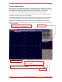
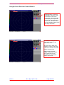
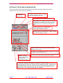
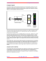
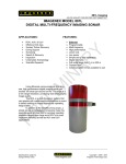
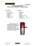
1
Please re
ead this man
nual carefullly before se
etting-up an
nd using you
ur system
SeaKing
g DF
FS &
S Princ
SeaP
ce Sona
S ar
Ope
erato
or & Insttallation
nual
Man
Supplied By
The electro
onic version
n of this doc
cument is th
he controlled
d copy. The
erefore all
printed ve
ersions of th
his document are uncontrolled.
For the
e latest ma
anual revision always
s visit “www
w.tritech.co
o.uk”
Issu
ue 9
TIL – En
ng – Spec – 027
Se
eaKing DFS & SeaPrinc
ce Sonar OIM
M
COPYRIGHT
© Tritech International Ltd
The copyright in this document is the property of Tritech International
Limited. The document is supplied by Tritech International Limited on
the understanding that it may not be copied, used, or disclosed to
others except as authorised in writing by Tritech International Limited.
Tritech International Limited reserved the right to change, modify and
update designs and specifications as part of their ongoing product
development programme.
F063.1
Tritech International Ltd
SeaKing DFS & SeaPrince Sonar OIM
Handling of Electrostatic-Sensitive Devices
4
Safety Statements
6
Technical Support
6
SEAKING DFS & SEAPRINCE Head INTRODUCTION
7
ST Head Installation
8
Subsea sensor Electrical Installation
8
ST Head Subsea Interconnect Cabling
9
SEAKING ARCNET Communication Configuration
10
Ground Fault Monitoring Equipment
11
mechanical installation
11
Using The Seaking Sonar
12
SEAKING Scanning Sonar Operating Notes
13
Screen Display and Controls ............................................................................................. 13
F3-Zoom Control Button .................................................................................................... 14
Zoom Mode Button ............................................................................................................ 15
Swap Control Button ......................................................................................................... 16
Using the Scan Direction Control Buttons ......................................................................... 18
Setting Up the Sonar Configuration
19
dynamic range
20
Sonar Slope control
20
Maintenance of The SEAKING Heads
21
Trouble Shooting
21
Symptoms:......................................................................................................................... 21
SEAKING SCU Head Status Codes.................................................................................. 22
SEAKING DFS Specification
22
SEAPRINCE Specification
23
Issue 9
TIL – Eng – Spec – 027
Page 3 of 23
Tritech International Ltd
SeaKing DFS & SeaPrince Sonar OIM
Handling of Electrostatic-Sensitive Devices
Attention
Observe Precautions for handling
Electrostatic Devices
Caution
Handling of Electrostatic-Sensitive Devices
Certain semiconductor devices used in the equipment are liable to damage due to static voltages.
Observe the following precautions when handling these devices in their unterminated state, or sub-units
containing these devices:
•
Persons removing sub-units from any equipment using electrostatic sensitive devices must be earthed by a
wrist strap via a 1MΩ resistor to a suitable discharge reference point within the equipment.
•
Soldering irons used during any repairs must be low voltage types with earthed tips and isolated from the
Mains voltage by a double insulated transformer. Care should be taken soldering any point that may have a
charge stored.
•
Outer clothing worn must be unable to generate static charges.
•
Printed Circuit Boards (PCBs) fitted with electrostatic sensitive devices must be stored and transported in
appropriate anti-static bags/containers.
F110.0
Issue 9
TIL – Eng – Spec – 027
Page 4 of 23
Tritech International Ltd
SeaKing DFS & SeaPrince Sonar OIM
Warranty Statement
Tritech International Limited herein after referred to as TIL
TIL warrants that at the time of shipment all products shall be free from defects in material and workmanship and suitable
for the purpose specified in the product literature.
The unit/system warranty commences immediately from the date of customer acceptance and runs for a period of 365
days. Customer acceptance will always be deemed to have occurred within 72 hours of delivery.
Note: Any customer acceptance testing (if applicable) must be performed at either TIL premises or at one of their
approved distributors unless mutually agreed in writing prior to despatch.
Conditions:
These include, but are not limited to, the following:
1
The warranty is only deemed to be valid if the equipment was sold through TIL or one of its approved distributors.
2
The equipment must have been installed and commissioned in strict accordance with approved technical
standards and specifications and for the purpose that the system was designed.
3
The warranty is not transferable, except or as applies to Purchaser first then to client.
4
TIL must be notified immediately (in writing) of any suspected defect and if advised by TIL, the equipment subject
to the defect shall be returned by the customer to TIL, via a suitable mode of transportation and shall be freight
paid.
5
The warranty does not apply to defects that have been caused by failure to follow the recommended installation or
maintenance procedures. Or defects resulting from normal wear & tear, incorrect operation, fire, water ingress,
lightning damage or fluctuations in vehicles supply voltages, or from any other circumstances that may arise after
delivery that is out with the control of TIL.
(Note: The warranty does not apply in the event where a defect has been caused by isolation incompatibilities.)
6
The warranty does not cover the transportation of personnel and per diem allowances relating to any repair or
replacement.
7
The warranty does not cover any direct, indirect, punitive, special consequential damages or any damages
whatsoever arising out of or connected with misuse of this product.
8
Any equipment or parts returned under warranty provisions will be returned to the customer freight prepaid by TIL
9
The warranty shall become invalid if the customer attempts to repair or modify the equipment without appropriate
written authority being first received from TIL.
10
TIL retains the sole right to accept or reject any warranty claim.
11
Each product is carefully examined and checked before it is shipped. It should therefore be visually and
operationally checked as soon as it is received. If it is damaged in anyway, a claim should be filed with the courier
and TIL notified of the damage.
Note: TIL reserve the right to change specifications at any time without notice and without any obligation to
incorporate new features in instruments previously sold.
Note: If the instrument is not covered by warranty, or if it is determined that the fault is caused by misuse, repair
will be billed to the customer, and an estimate submitted for customer approval before the commencement of
repairs.
F167.1
Issue 9
TIL – Eng – Spec – 027
Page 5 of 23
Tritech International Ltd
SeaKing DFS & SeaPrince Sonar OIM
Safety Statements
NOTE
Throughout the manual certain potential problems, or further information
relating to the installation, maintenance, understanding or use of the
apparatus will be highlighted to the operator by indications identified by
the adjacent symbol and text.
CAUTION!
Throughout the manual certain safety or operational related comments
and requirements will be highlighted to the operator by indications
identified by the adjacent symbol and text.
DANGER!
Throughout the manual certain safety or operational related comments
and requirements that could lead to injury or loss of life will be highlighted
by the adjacent symbol and text.
Technical Support
Contact your local agent or Tritech International Ltd
Mail
Tritech International Ltd.
Peregrine Road,
Westhill Business Park,
Westhill, Aberdeen,
AB32 6JL, UK
Telephone
++44 (0)1224 744111
Fax
++44 (0)1224 741771
Email
[email protected]
Web
www.tritech.co.uk
An out-of-hours emergency number is available by
calling the above telephone number
If you have cause to use our Technical Support service, please ensure that you have the
following details at hand prior to calling:
•
•
•
System Serial Number (if applicable)
Fault Description
Any remedial action implemented
Due to the expansion of equipment capabilities and the fact that new sub-modules are
continually being introduced, this manual cannot detail every aspect of the operation.
Issue 9
TIL – Eng – Spec – 027
Page 6 of 23
Tritech International Ltd
SeaKing DFS & SeaPrince Sonar OIM
SEAKING DFS & SEAPRINCE HEAD INTRODUCTION
The Sonar and Profiler heads operate over a 360 degree scanning field, of frequencies of
either 325, 580, 675, 795, or 1100kHz, giving ranges of up to 300m. The heads are available
in standard ‘Vertical’ body configuration, (with tall boot for narrow beam transducer). The
heads are able to continuously, or part-scan the full 360 degree sector in either direction.
There can be one or more sonar or profiler heads used in a system. The profiler heads can
operate in various scan modes depending on user set-up in the SeaKing SCU.
The transducer arrays within the heads are available in different configurations for various
beam shapes. The transducer head and motor are pressure compensated within an oil-filled
semi-rigid boot. The electronics are contained within the body tube in dry air at one
atmosphere pressure. The sonar body is machined from aluminium alloy, and has a hardanodised coating.
A waterblock is fastened to the body tube of the head, and provides a 4000metre rated
pressure bulkhead. The 6-way underwater connector is secured to the waterblock fitted to the
body tube using four cap screws, this connects to the pins on the PSU/COMMS PCB. An Oring seals the connector to the waterblock.
The ST SeaKing DFS and SeaPrince have improved features over the Series 2 Sonar and
Profiler heads, these are outlined below.
• Scan rate
The heads can achieve a scan rate of up to 180° per second - the actual physical acoustic
limit. The scan rate is significantly faster, particularly on short ranges, than the Series 2 head,
and may be up to 10 times faster on ranges up to 30 metres irrespective of the scan speed
selected. This gives faster target acquisition, and helps in obstacle avoidance.
• Dual Frequency Operation (SeaKing only)
The SeaKing DFS can use up to two operating frequencies - one giving long range target
acquisition characteristics and the other giving shorter range imaging capability. It is
effectively two sonars in a single housing. The lower frequency operation is extremely useful
for long range target acquisition - again, important when avoiding potential targets. The higher
frequency is then used for high definition work.
Each of the two operating frequencies may be offset from the centre frequency e.g. the 325
kHz transducer may be digitally tuned between 305 and 345 kHz. This can be very useful if
you have another piece of equipment with a similar operating frequency or if 325 kHz is a
harmonic of the operating frequency of another piece of equipment. These frequency
alterations are remotely carried out using the SeaKing SCU.
• Protected transducer
The SeaKing DFS has a semi-rigid oil-filled plastic boot which offers a much greater
protection than previous models, to the sonar transducer if subjected to impact. Should the
sonar be impacted the boot can absorb this without damage. If an excessive impact occurs
the damage is usually limited to writing-off of a transducer/ motor. The unit has no rotating
seals to be damaged or wear.
In the case of the Composite Transducer being fitted to the head, the boot is manufactured
from a rigid (Acetal) material. This is a very strong and will flex if subjected to a heavy impact.
• Electrical Connection
The SeaKing & SeaPrince heads use the same 6 way U/W Connector as per Series 2 Sonar
Heads.
Issue 9
TIL – Eng – Spec – 027
Page 7 of 23
Tritech International Ltd
SeaKing DFS & SeaPrince Sonar OIM
ST HEAD INSTALLATION
The SeaKing DFS and SeaPrince heads are supplied with their own waterblock / connector
with a length of polyurethane jacketed cable (sonar - 1metre, profiler 3metre).
Depending on the specification of the system, this cable will either need to be terminated to a
suitable connector appropriate to the operators equipment, or may be supplied with a cable
assembly to one or more additional connectors.
The waterblock is fastened to the body tube of the head, and provides a 4000metre rated
pressure bulkhead.
This will protect the electronics from water ingress in case the connector is damaged or not
fitted correctly. The connector may be disconnected from the heads by unscrewing the four
securing screws and removing the connector from the waterblock.
CAUTION!
It is not necessary to remove the water block when removing the connector
or taking the head apart. Whilst the connector is removed from the head, the
blanking plugs supplied should be fitted to prevent the ingress of dirt or
moisture.
SUBSEA SENSOR ELECTRICAL INSTALLATION
The SeaKing range of Subsea Sensors are designed to work from a smoothed DC power
supply of 18v-36v DC (Absolute Maximum 36v DC).
If using a rectified transformer PSU, the output of the PSU must have a filter capacitor of not
less than 470μF, for each head being powered.
If an unregulated PSU is used, then make sure that the voltage value measured at the head is
in the range 18-36v DC, in power on/off and running conditions.
If powering the head(s) down a long lead or umbilical, the maximum recommended loop
resistance of the power line must not exceed 10Ω for one head, 5Ω for two heads, and 3Ω for
three heads.
CAUTION!
CAUTION!
Issue 9
If the supplied voltage is less than 18v dc the head may not operate
correctly.
Never try to make SeaKing DFS system heads work down a long cable
by increasing the PSU output voltage above 36v DC. A 48VDC PSU
Option is available that will allow operation up to 70VDC for long line
applications.
TIL – Eng – Spec – 027
Page 8 of 23
Tritech International Ltd
SeaKing DFS & SeaPrince Sonar OIM
ST HEAD SUBSEA INTERCONNECT CABLING
The Underwater Connector supplied is 6 way, the wiring code is shown below.
CAUTION!
The numbers shown relate to all schematic diagrams, (not a DIN style
format).
1
1
6
2
2
3
3
5
4
5
4
Connector
Face View
6
ARCNET-A (RS-232 Tx)
ARCNET-B (RS-232 Rx)
+24v DC
(+24v DC)
0v DC
(0v DC)
(RS-232 Gnd)
HEAD CHASSIS
Yellow
Blue
Red
Black
Green
Screen
Fig. 1.0 ST 6 Way Underwater Connector Wiring Configuration
Pin-outs for optional single-node RS-232 communications are shown in italics.
See the document “SeaKing Serial Communication Manual” for more information on RS232
configuration and baud setup.
AIFV3B J2.1
D15M
Connector
6w
U/W Connector
Pin 3 Red +24v DC
Pin 8 Yellow
Pin 15 Blue
Surface
Termination
Resistor
Pin 4 Black 0vDC
Pin 1 Yellow
Pin 2 Blue
Subsea
Termination
Resistor
* Fitted in supplied
connector
* Fitted in Junction Box or suitable location
IMPORTANT NOTE :
1) Termination resistors - Surface and Subsea - fitted to
twisted pair to enable good communications. Install
270R Surface and 39R Subsea. Refer to ‘SYSTEM’
section of manual for more details.
SeaKing Sonar ARCNET communications - typical connections
Fig. 1.1 SeaKing Communication ARCNET Wiring Diagram
Issue 9
TIL – Eng – Spec – 027
Page 9 of 23
Tritech International Ltd
SeaKing DFS & SeaPrince Sonar OIM
SCU 15-way “D” type
Tritech 6-pin connector
1
------------------------[ RS-232 Uplink ]--------------------
13
2
----------------------[ RS-232 Downlink ]------------------
6
5
-----------------------[ RS-232 Ground ]-------------------
2
3
-------------- 24Vdc Supply
4
-------------- 0V Supply
Fig. 1.2 SeaKing Communication (optional) RS-232 Wiring Diagram
SEAKING ARCNET COMMUNICATION CONFIGURATION
All SEAKING systems communicate standard using ‘ARCNET’ multi-drop, networked
communications over the twisted cable pair. It is also possible to interface the ARCNET to
wideband multiplex or systems, contact Tritech for details.
NOTE: The system also has an RS-232 option for controlling a single* sensor head directly
from the surface. Configuration details are supplied in another manual section that can be
provided by Tritech if not included (*This is not multi-drop)
CAUTION!
Normally the ’ARCNET’ does require a termination resistor to be fitted at each
end of the umbilical. Normally this is supplied fitted within the D connector at the
surface, and is left for the user to fit at the subsea end in a convenient ‘J’ box.
This is the easiest system to adopt when using multiple sensors on the network.
However if just one device is in use it may be more convenient to fit the resistor
inside the subsea unit. Devices fitted with a termination resistor should be
appropriately labeled, but the user can check by measuring the resistance
between pins 1 and 2 on the water block connector.
For unusual cable lengths or cable types refer to the System Manual for details
of other terminations options.
Compatibility Issues With Earlier Tritech Systems
The SEAKING SCU, SeaKing DFS and SeaPrince sonar heads cannot be used with RS-232 /
RS-485 AIF Cards as used in earlier WINSON based SCU-3 systems, and must be used with
AIF-SEAKING ARCNET (AIFV3) Cards.
RS-232/RS-485 Series 2 Sonar, Profiler and other heads cannot be directly used with
SEAKING systems, contact Tritech or local agent for details.
Issue 9
TIL – Eng – Spec – 027
Page 10 of 23
Tritech International Ltd
SeaKing DFS & SeaPrince Sonar OIM
GROUND FAULT MONITORING EQUIPMENT
The power supply within SEAKING subsea heads includes an electrically isolated DC-DC
converter front end, There is a small capacitive connection to the sonar chassis which should
not noticeably affect any impressed current ground fault indicator (GFI) equipment
MECHANICAL INSTALLATION
CAUTION!
Although the sonar and profiling heads are rugged, they should be
handled with care, particularly the connector and transducer heads. It is
strongly recommended that a substantial guard is fitted over the
scanning heads to protect the transducer and drive electronics from
impact damage.
The heads should be secured by clamping on the cylindrical body section such that the
transducer head is unimpeded or shielded. Any metallic clamps should be electrically
insulated from the sonar body by means of rubber or plastic strips or mount brackets of at
least 3 mm thickness and extending at least 3 mm beyond the clamp boundary to reduce any
galvanic corrosion effect. Non-metallic clamps are preferable: if metallic clamps are used
(especially if they are other than aluminium ) they should be painted or lacquered with at least
two or three coatings. Brass or bronze materials should be avoided unless they have an
aluminium content as their copper content causes serious corrosion problems when in
proximity to aluminium components.
Care should be taken to mount sonar/profiling heads to ensure that they are mounted as
close to the true vertical or horizontal as possible ( i.e. vertical for scanning heads ; horizontal
for profiling heads ) in relation to the trim position of the vehicle. The front filling plug and red
LED should be aligned with the natural direction of travel of the vehicle on scanning sonars
and pointed directly downwards in the case of profiling sonars. This is important since errors
in the head alignment can give rise to unreliable results.
Important
Scanning sonar heads may be mounted with the transducer uppermost or down, but the
correct orientation must be selected in the sonar configuration tools to display the scan data
correctly.
Similarly profilers may be mounted with transducers forward or back.
Issue 9
TIL – Eng – Spec – 027
Page 11 of 23
Tritech International Ltd
SeaKing DFS & SeaPrince Sonar OIM
USING THE SEAKING SONAR
On completion of installation of the sonar on a vehicle, it can be tested in air by powering up
the system and observing that the red LED illuminates as the head scans through the ahead
direction.
As with any acoustic sonar, the ST Sonar heads only show echoes of objects that reflect
sound back to the sonar transducer, such that hard shiny surfaces are sometimes only seen
when they are at right angles to the sonar beam. Rough seabed textures can blot out smaller
targets completely. The plan view also does not show how high an object is, unless a shadow
is cast, in which case the length of the shadow is related to the height of the object, its range,
and the height of the sonar head.
The SeaKing DFS Sonar is normally supplied with two operating frequencies, typically 325
kHz and 580 or 675 kHz. The lower 325 kHz frequency is capable of detecting large targets at
ranges in excess of 200 metres. The higher frequency has a narrow beam and shorter (100m)
range for more detailed images of closer targets. Switching between the two operating
frequencies is by using RAT button F5. The current operating frequency is indicated in the F5
panel above the sonar display. If operating on range scales greater than 100 metres, use the
lower frequency for maximum range performance.
The SeaPrince has a single frequency transducer - typically 675kHz.
Interpretation of sonar data develops with experience. Sonar reflections of isolated small
objects give no indication of shape or attitude. Man made structures, such as platforms or
rock walls tend to have regular patterns that are easier to identify. Using sonar is rather like
looking at a world made of shiny black plastic, in the dark, with only a narrow torch beam for
illumination. Remember that when close to large objects, or in a depression in the seabed,
that the viewing range may be severely limited. Very strong reflectors may give multiple
echoes along a bearing line, and are identified by being equispaced in range. If they persist,
reduce the "Gain".
When searching for objects, keep the vehicles heading as steady as possible to stop the
image blurring. Sit on the seabed if necessary. If using side scan mode for searching, keep
the vehicle depth steady, at longer ranges fly the vehicle a few metres above the seabed
(typically 10% of the range scale in use) to improve the detection range and picture quality.
Depending on water depth and vehicle depth, there may be ring like echoes. These can be
caused by surface or seabed direct reflections and may be difficult to avoid.
Experience with the sonar will enable the operator to be able to quickly and effectively set the
"Gain" and "Threshold" controls to give as even a background as possible, without swamping
the display, and maximise the performance capabilities of the head. The threshold control is
used to mask out any unwanted clutter caused by the weaker returns.
There are 4 range resolutions available, selected from the Main Menu. As you increase the
resolution from Low to Medium to High to Ultimate, the sonar display will show better
resolution, but at a lower scan speed. Use of a lower resolution will give faster scan speed,
but with coarser detail. When searching for smaller targets close by, select a higher resolution
mode at the higher frequency. When searching for large targets at long range use a lower
resolution on a lower frequency
The Time Variable Gain (TVG) Slope may be adjusted to improve sonar return balance on
longer ranges. Only use this control after setting the main gain control to achieve good results
close to the sonar head.
Issue 9
TIL – Eng – Spec – 027
Page 12 of 23
Tritech International Ltd
SeaKing DFS & SeaPrince Sonar OIM
SEAKING SCANNING SONAR OPERATING NOTES
Screen Display and Controls
The Main Areas of the Sonar Display are identified below:
Sonar Toolbar
‘Tools’ menu
(Spanner Icon)
Sonar
Paus
‘Menu’
Option
Range Scale
Low/High
Frequency
Resolution
Main Sonar Controls
Cursor
Co-ordinates
Sensor Display
Area.
System Status
Bar.
Issue 9
‘Log’
Options
Display Header
Function Keys
F1 - F6 (Green
RAT buttons)
TIL – Eng – Spec – 027
Screen
Freeze
User Boxes
‘Max’ Button. Clicking
this control will toggle
between normal screen
view (as shown above)
and a full screen view of
the Sensor Display
Area
Page 13 of 23
Tritech International Ltd
SeaKing DFS & SeaPrince Sonar OIM
F3-Zoom Control Button
When ‘F3-Zoom’ is selected, either by RAT-F3, Keyboard-F3 or Clicking Menu Bar F3-Zoom,
the ‘Zoom Window’ is activated. To examine an area of the display in the Zoom Window, Click
the Left Button and move the Trackball cursor to the area of interest. A red ‘Zoomed
Rectangle’ on the Sonar Display indicates the area displayed in the Zoom Window.
Moving the cursor over the Sonar Display area causes the Range and Relative Bearing from
the Reference Point to the Cursor to be updated.
Normally the Reference Point is the sonar head location, but it can be moved to anywhere on
the Sonar Display Area by moving the cursor and clicking the Right Button. This causes a
Red Cross to be displayed at the chosen reference point, and the Range and Bearing
displayed are now relative to the chosen position and Sonar Ahead Direction. Clicking the
Right Button again will cause the Reference point to return to the Sonar Location and the Red
Cross to disappear.
Zoom Scale
Range and Relative Bearing from Reference
Point to Centre of Zoomed Rectangle
Zoomed Rectangle
Zoom Mode Button. Click this button to
switch between Sonar Zoom and Image
Pixel Zoom Modes
Swap Control Button. Click this button to swap Sonar Display between
Main Sonar Window with Zoom Window
Zoom Window
Issue 9
TIL – Eng – Spec – 027
Page 14 of 23
Tritech International Ltd
SeaKing DFS & SeaPrince Sonar OIM
Zoom Mode Button
Left Clicking the Zoom Mode Button will switch the Zoom mode between Zoom Sonar Mode
and Zoom Image Mode.
Zoom Sonar Mode is a true zoom of the sonar data, to the maximum display resolution of the
Sonar, and effectively produces a 1600 pixel resolution view in the display window. This
image is only updated by new sonar data
Zoom Image mode is a bitmap magnification of the main sonar display window, and can be
used to magnify any data within the main sonar window.
Zoom mode button.
Issue 9
TIL – Eng – Spec – 027
Page 15 of 23
Tritech International Ltd
SeaKing DFS & SeaPrince Sonar OIM
Swap Control Button
Swap Control Button
If you want to see a larger ‘zoomed’ area of the Sonar display, the ‘Swap Control ‘ causes the
Main Sonar display window and the Zoom display window to be swapped.
When ‘swapped’ the Main sonar display is reduced in size to fit the normal zoom window
area, and the main window area is used as the zoom window at maximum sonar resolution.
Left Clicking the Swap control toggles the Swap display mode.
When ‘Swapped’, the ‘Image Zoom’ function is not available.
The Range and Relative Bearing indicator panels are valid when the cursor is in the
appropriate window.
Range & Bearing
indicators
Issue 9
TIL – Eng – Spec – 027
Swap Control Button
Page 16 of 23
Tritech International Ltd
SeaKing DFS & SeaPrince Sonar OIM
Clicking the ‘Right’ Trackball Button in the Sonar
Display or the Zoom Display areas allows a reference
point to be set, marked as a Red + as shown below.
When this Cross is visible the Range and Bearing
information is shown relative to this cross.
Click the Right Trackball button to disable and reenable the offset reference point
Issue 9
TIL – Eng – Spec – 027
Page 17 of 23
Tritech International Ltd
SeaKing DFS & SeaPrince Sonar OIM
Using the Scan Direction Control Buttons
The Red buttons on the Rat
and Display control the sonar
scanned area. The centre
button gives a 360 degree all
round display. The Top button
gives a Look Ahead view as
shown here. The other buttons
give corresponding views to the
Left, Right and Astern
For Example, Clicking the Red
‘Left’ button, selects a 180
sector to the Left.
The Scan Sector Width and
Direction controls can be used
to alter scan direction and width
within a sectored view
Note: Enabling the ‘Max
Display’ control in the ‘Tools’
menu (spanner icon) will
maximise the sonar display
area (as shown left).
Issue 9
TIL – Eng – Spec – 027
Page 18 of 23
Tritech International Ltd
SeaKing DFS & SeaPrince Sonar OIM
SETTING UP THE SONAR CONFIGURATION
These Sonar Setup controls are automatically remembered if the Sonar System is shut down
using the ‘Exit’ commands, prior to powering off.
Click this button to
reset system to
default controls.
Operating range units; M=Metres, Ft=Feet,
Fm=Fathoms, Yd=Yards. Click this control to
cycle through available range units.
Close tools menu and keep current settings.
For Seaking set un-checked for sonar mounted with
transducer boot up, checked for transducer boot down.
For SeaPrince set checked for sonar mounted with
transducer boot up, un-checked for transducer boot
down.
Extended options menu. Enable ‘More
Options’ flag to display this menu.
Operating Frequency Adjust Slider Bar. Allows the sonar
operating frequency to be shifted by +/- 20kHz. ‘F Reset’
button resets frequency to normal.
Compass Stabilisation selector. If your system has a sonar
compass interface, check this box to enable the compass
stabilised sonar functions.
Check this box to enable Range Labelling. Operating range units
are Metres, Feet, Fathoms & Yards.
NOTE: Individual
Sens / Slope settings
for both Sonar
frequencies (V1.39 ->).
Screenlock allows capture data to be limited to that sufficient to fill
the sonar screen. Also reduces log file sizes if enabled.
Dynamic Range Controls; SENSitivity and SLOPE (default settings = ‘Med’).
The sonar data is sampled over 0-80dB. The Sensitivity control raises (‘High’) or lowers (‘Low’)
the base sampling level. Note: The ‘Contrast’ control - available on the RAT - adjusts the size
of the sampling window; set a lower value to increase the contrast (see following section on
Dynamic Range). Set the Slope control to ‘High’ to increase the slope uniformally over all
ranges and set to ‘Low’ to decrease uniformally over all ranges.
Issue 9
TIL – Eng – Spec – 027
Page 19 of 23
Tritech International Ltd
SeaKing DFS & SeaPrince Sonar OIM
DYNAMIC RANGE
The dynamic range controls should be used with care. If used properly, however, they can
become very useful tools. The Dynamic Range controls - Sensitivity and Contrast -can be
adjusted to set the sampling range of the Sonar Receive Signal, which extends from 0dB to
80dB. The following diagram describes operation;
80dB
26
0dB
RECEIVE SIGNAL
DYNAMIC
RANGE
CONTROL
SCREEN
COLOUR
SCALE
The sonar receiver will accept a return signal in the region of 0 - 80dB. The dynamic range
controls are used to adjust the position of a sampling window within the 0-80dB dynamic
range band of the receive signal.
By switching the Sensitivity control - available under the ‘Tools’ menu - between ‘Low’, ‘Med’
and ‘High’, the position of the receiver’s sampling window is adjusted within this 0 - 80dB
window. Setting the Sensitivity control to ‘Low’ will move the sampling window to the lower
end of the 0 - 80dB scale. This will produce a more saturated display with greater weak-return
content. ‘Med’ is the default setting for this control and will produce the best all-round display.
Set the Sensitivity control to ‘High’ to omit background noise and low level returns seen at the
receiver.
The Contrast ‘RAT’ control is used to adjust the width of the sampling window. The sampling
window can be any size between ranges of 9 - 25dB. Set this value low to decrease the size
of the sampling window and accordingly increase the sonar display contrast. Ideally the
control should be set somewhere in the centre of the allowed range (16 - 18 dB) to give the
best results under most conditions. Select a high value to reduce the contrast of the sonar
display.
SONAR SLOPE CONTROL
This sets the slope of the time varying gain which applies more receive gain for distant targets
to compensate for through water losses on the acoustic signal. The normal settings is
medium ('Med'), but if far targets appear weak in comparison with close targets the 'High'
setting should be selected. Conversely if far targets are strong in comparison to near targets
then the 'Low' setting should be used.
Issue 9
TIL – Eng – Spec – 027
Page 20 of 23
Tritech International Ltd
SeaKing DFS & SeaPrince Sonar OIM
MAINTENANCE OF THE SEAKING HEADS
There are no user-serviceable parts in the sonar or profiling heads and no components
requiring routine maintenance.
It is recommended that sonar and profiling heads be rinsed down with fresh water after each
dive and especially if the unit is not going to be used for extended periods.
Although the anodised aluminium components are very resistant to corrosion, using fresh
water is a simple way of minimising the chance of corrosion.
Wherever possible, avoid any prolonged exposure to extreme climatic and weathering
conditions to reduce any aging effects on the protective boot and connectors.
TROUBLE SHOOTING
Symptoms:
1 Continuous Status "No Comms" message.
This indicates that there is no communication with the device flagged. Check the power and
communications links to the sonar head for continuity and for correct polarity, voltage and
ensure that the power supply can provide sufficient current to power all devices. If necessary
refer to the service section to check that the head internal fuses have not blown
If a cable flood is suspected, then the conductors will need to be insulation tested; the sonar
heads and SEAKING SCU must be disconnected as described in the Service Manual.
CAUTION!
This is especially critical if a cable insulation tester is used to check
resistance between conductors, as serious damage to the
Scanning/Profiling heads and SEAKING SCU will occur if the correct
procedure is not followed.
2 Other Status Messages.
Refer to the SEAKING SCU Head Status Codes
3 Sonar head rotates but no targets observed
Check the gain control is responding and not set at a minimum.
Listen to sonar head in air. If it "clicks" audibly then the transmitter circuit is OK.
Check that the sonar was not operated in clear water where there were no sonar targets.
Click the [Reset Controls] button in the Sonar Tools menu to return to default system settings
4 No seabed sonar targets observed.
SEAKING Scanning sonars generally have a vertical beam width of 20 - 40 degrees about a
centre line i.e. plus and minus 10 - 20 degrees. The following guide indicates the approximate
first seabed return for a given transducer height off the seabed :
Height First return
1 metre
2 - 4 metres
1.5 metres
3 - 7 metres
2 metres
4 - 9 metres
Issue 9
TIL – Eng – Spec – 027
Page 21 of 23
Tritech International Ltd
SeaKing DFS & SeaPrince Sonar OIM
SEAKING SCU Head Status Codes
Code
No reply
Busy
Possible Reason or Fault giving Error Code
Sonar or Profiler head not powered up, or comms fault.
Head is centering on power-up, or head has lost centre during scan.
SEAKING DFS SPECIFICATION
Overall length
Body tube diameter
Maximum diameter
Weight in air
Weight in water
Frequency
Range resolution
Mechanical resolution
Maximum range
Scan size
Depth rating
Materials
Finish
Operating temperature
Storage temperature
Power requirements
Data communications
Drive capability (ARCNET only)
Isolation (ARCNET only)
Issue 9
221 mm (excluding connector)
99 mm
110 mm
2.0 kg
1.1 kg
See configuration sheet
<50 mm
<0.5°
300m( @ 325kHz)
Variable up to 360°
4000 m
Auminium alloy - HE30, RPU
Hard anodised Black
-10°C to +35°C
-20°C to +50°C
18v-30v DC (Abs. Max. 36v DC) @ 9 Watts max.
ARCNET multi-drop
1,500m (full Baud rate) / 2,500m (1/2 Baud rate)
Transformer Isolated 1500v
TIL – Eng – Spec – 027
Page 22 of 23
Tritech International Ltd
SeaKing DFS & SeaPrince Sonar OIM
SEAPRINCE SPECIFICATION
Overall length
Maximum diameter
Weight in air
Weight in water
Frequency
Range resolution
Mechanical resolution
Maximum range
Scan size
Depth rating
Materials
195 mm
70 mm
1.0 kg
0.5 kg
See configuration sheet (typical 675kHz)
<50 mm
<0.5°
100m( @ 675kHz)
Variable up to 360°
3000 m
Auminium alloy - HE30, RPU
Finish
Operating temperature
Storage temperature
Power requirements
Data communications
Drive capability (ARCNET only)
Isolation (ARCNET only)
Hard anodised Black
-10°C to +35°C
-20°C to +50°C
18v-30v DC (Abs. Max. 36v DC) @ 9 Watts max.
ARCNET multi-drop
1,500m (full Baud rate) / 2,500m (1/2 Baud rate)
Transformer Isolated 1500v MIN
Issue 9
TIL – Eng – Spec – 027
Page 23 of 23