1
Kyland-USA
KY-3000EM
Industrial Managed Ethernet Switch
User’s Manual
Version 4.0
July 2014
Compliant: For Military Contracts that require the continuous
monitoring and protection of Industrial Control Systems (ICS)
Networks Operating / monitoring the operating utilities such as
Water, Sewer, Electrical, Security, Video, Building Controls,
Street and Intelligent Transportation Systems (ITS)
www.Kyland-USA.com
Table of Contents
1 PREFACE ....................................................................................................................................... 1
1.1 CONVENTIONS ................................................................................................................................. 1
1.2 DEVICE INTRODUCTION ................................................................................................................... 1
1.2.1 Brief Introduction ................................................................................................................ 1
1.2.2 Port Introduction ................................................................................................................. 2
1.2.3 Indicator Introduction ........................................................................................................ 2
1.2.4 Default Configuration ......................................................................................................... 3
1.2.5 Login to the Switch ............................................................................................................. 3
1.2.6 WEB Management Overview ............................................................................................ 4
2 SYSTEM INFORMATION .............................................................................................................. 6
3 ADVANCED CONFIGURATION ................................................................................................... 7
4 PORT MANAGEMENT .................................................................................................................. 8
4.1 PORT CONFIGURATION .................................................................................................................... 8
4.2 PORT AGGREGATION....................................................................................................................... 9
4.2.1 Aggregate Groups .............................................................................................................. 9
4.2.2 LACP Port Setting ............................................................................................................. 10
4.2.3 Aggregate Basic Setting ................................................................................................. 11
4.2.4 LACP Status Setting ......................................................................................................... 11
4.3 PORT BANDWIDTH ......................................................................................................................... 11
4.4 PORT MIRRORING.......................................................................................................................... 12
5 VLAN ............................................................................................................................................. 14
5.1 ADVANCED ..................................................................................................................................... 14
5.2 802.1Q VLAN .............................................................................................................................. 15
5.2.1 802.1Q VLAN Setting ........................................................................................................ 16
5.2.2 802.1Q Configuration ....................................................................................................... 16
5.2.3 802.1Q Port ......................................................................................................................... 17
5.3 GARP SETTING ............................................................................................................................ 17
5.3.1 GARP .................................................................................................................................... 18
5.3.2 GVRP .................................................................................................................................... 19
5.3.3 GMRP ................................................................................................................................... 20
6 QOS ............................................................................................................................................... 21
6.1 QOS CONFIGURATION ................................................................................................................... 21
6.1.1 General Priority ................................................................................................................. 21
6.1.2 Port QoS Configuration ................................................................................................... 21
6.2 SCHEDULING MECHANISM ............................................................................................................ 22
6.3 TRANSMIT QUEUES ....................................................................................................................... 22
6.4 DSCP M AP ................................................................................................................................... 23
7 FORWARDING ............................................................................................................................. 24
7.1 UNICAST MAC ADDRESS.............................................................................................................. 24
7.1.1 MAC Address ..................................................................................................................... 24
7.1.2 Dynamic Unicast MAC ..................................................................................................... 25
7.2 MULTICAST MAC ADDRESS ......................................................................................................... 25
7.3 IGMP SNOOPING CONFIGURATION .............................................................................................. 27
7.3.1 IGMP Snooping .................................................................................................................. 28
7.3.2 Route Port ........................................................................................................................... 28
i
7.3.3 Misc ...................................................................................................................................... 29
8 SECURITY .................................................................................................................................... 31
8.1 M ANAGEMENT SECURITY .............................................................................................................. 31
8.2 PORT AUTHENTICATION ................................................................................................................ 32
8.2.1 802.1x Port .......................................................................................................................... 33
8.2.2 802.1x Misc ......................................................................................................................... 34
8.3 MAC AUTHENTICATION ................................................................................................................. 35
8.3.1 Port Configuration ............................................................................................................ 35
8.3.2 Misc ...................................................................................................................................... 36
8.3.3 Authentication Information ............................................................................................. 36
8.4 STORM CONTROL .......................................................................................................................... 36
9 LLDP ............................................................................................................................................. 38
9.1 M ANAGEMENT LLDP .................................................................................................................... 38
9.1.1 Configuration ..................................................................................................................... 38
9.1.2 TLVs ...................................................................................................................................... 41
9.1.3 LLDP Parameters .............................................................................................................. 41
9.2 NEIGHBOR INFORMATION .............................................................................................................. 42
9.3 LLDP STATISTICS ......................................................................................................................... 42
10 STATISTICS ................................................................................................................................ 43
10.1 PORT STATUS .............................................................................................................................. 43
10.2 PORT STATISTICS ........................................................................................................................ 43
10.3 VLAN LIST .................................................................................................................................. 44
10.4 MAC ADDRESS TABLE ............................................................................................................... 44
10.4.1 Unicast MAC Address .................................................................................................... 44
10.4.2 Multicast MAC Address ................................................................................................. 44
10.5 IGMP SNOOPING GROUP ........................................................................................................... 44
10.6 LINK AGGREGATION .................................................................................................................... 45
10.6.1 Manual Trunking Group ................................................................................................ 45
10.6.2 Static Trunking Group ................................................................................................... 45
10.6.3 LACP Trunking Group ................................................................................................... 45
10.7 KY-ANILLO STATUS ..................................................................................................................... 45
11 SPANNING TREE....................................................................................................................... 46
11.1 STP ............................................................................................................................................. 48
11.1.1 Basic STP .......................................................................................................................... 48
11.1.2 STP Information ............................................................................................................... 49
11.1.3 STP Port Attributes ......................................................................................................... 49
11.2 RSTP .......................................................................................................................................... 50
12 KY-ANILLO CONFIGURATION ................................................................................................ 52
12.1 KY-ANILLO .................................................................................................................................. 52
12.2 KY-ANILLO COUPLING ................................................................................................................ 54
12.3 KY-ANILLO TIMER ....................................................................................................................... 55
13 SNMP MANAGER ...................................................................................................................... 56
13.1 SNMP ACCOUNT ........................................................................................................................ 57
13.1.1 SNMP Community ........................................................................................................... 57
13.1.2 SNMP User ........................................................................................................................ 57
13.2 SNMP TRAP ............................................................................................................................... 58
13.2.1 Global Trap ....................................................................................................................... 58
13.2.2 Trap Host IP ...................................................................................................................... 58
13.2.3 Trap Port ........................................................................................................................... 58
14 RMON.......................................................................................................................................... 60
ii
14.1 STATISTICS .................................................................................................................................. 60
14.2 HISTORY ...................................................................................................................................... 62
14.2.1 History control ................................................................................................................. 62
14.2.2 History List ....................................................................................................................... 62
14.3 ALARM ......................................................................................................................................... 63
14.4 EVENT CONFIGURATION .............................................................................................................. 65
14.4.1 Event .................................................................................................................................. 65
14.4.2 Event Log .......................................................................................................................... 66
15 PTP .............................................................................................................................................. 67
15.1 PTP CONFIGURATION ................................................................................................................. 67
15.2 PTP PORT ................................................................................................................................... 69
15.3 PTP STATUS................................................................................................................................ 69
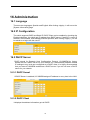
16 ADMINISTRATION ..................................................................................................................... 71
16.1 LANGUAGE .................................................................................................................................. 71
16.2 IP CONFIGURATION ..................................................................................................................... 71
16.3 DHCP SERVER ........................................................................................................................... 71
16.3.1 DHCP Server .................................................................................................................... 71
16.3.2 DHCP Client ...................................................................................................................... 71
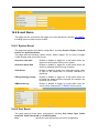
16.4 SNTP .......................................................................................................................................... 72
16.5 SMTP .......................................................................................................................................... 72
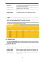
16.6 E-MAIL ALARM ............................................................................................................................ 73
16.6.1 System Event ................................................................................................................... 73
16.6.2 Port Event ......................................................................................................................... 73
16.7 RELAY ALARM ............................................................................................................................. 74
16.7.1 System Event ................................................................................................................... 74
16.7.2 Port Event ......................................................................................................................... 75
16.8 SYSTEM LOG ............................................................................................................................... 75
16.9 PING DIAGNOSIS ......................................................................................................................... 76
16.10 ACCOUNT .................................................................................................................................. 76
16.11 TFTP SERVICES........................................................................................................................ 77
16.11.1 Update Firmware ........................................................................................................... 77
16.11.2 Backup Configuration .................................................................................................. 78
16.11.3 Restore Configuration ................................................................................................. 78
16.12 REBOOT .................................................................................................................................... 78
16.13 RESET ....................................................................................................................................... 79
16.14 SAVE CONFIGURATION .............................................................................................................. 79
17 LOGOUT ..................................................................................................................................... 80
APPENDIX A ORDERING INFORMATION................................................................................... 81
APPENDIX B SUPPORTED MIBS ................................................................................................ 82
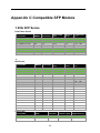
APPENDIX C COMPATIBLE SFP MODULE ................................................................................ 83
iii
1 Preface
This manual applies to industrial switches KY-3000EM.
1.1 Conventions
GUI Convention
Description
Boldface
Keywords on web management page are in Boldface
Italic
Tab page names are in italic
<>
Buttons are in <>
[]
Menus and submenus are in [ ].
Note
This icon is added to the notes.
Caution
Means reader be careful. Improper operation may cause data
loss or damage to equipment.
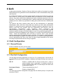
1.2 Device Introduction
1.2.1 Brief Introduction
KY-3000EM Industrial Ethernet Switches are designed to meet various industrial
application needs and provide customer with a high-end industrial Ethernet network
communication solution. KY-3000EM’ high availability and reliability, as well as the rich
security features make it ideal for data transmission securely. KY-3000EM provide
powerful management capabilities, and can be managed through Web, CLI,
Telnet/serial console, Windows utility and SNMP. It is designed to apply dual power
supplies for redundancy with wide DC input range and support DIN rail and wall
mounting for installation in industrial environments.
Ky-Anillo is a proprietary technology of our company. It is designed especially for
industrial applications, providing fast Ethernet ring protection and recovery within 20ms.
From the management interface, users can choose either port from normal Ethernet
port or trunk port to form an Ethernet ring for faster recovering and wider bandwidth to
keeping industrial applications running continuously.
1
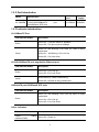
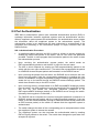
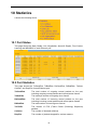
1.2.2 Port Introduction
Model
Console
port
Ethernet Port
7X10/100BaseTX
KY-3000EM +1X10/100/1000BaseTX
2X1000BaseX SFP slots
port
port
+ 1X RS232
Power
supply
2X24VDC
1.2.3 Indicator Introduction
10/100BaseTX Port
Port Indicator Status
Description
Green On —The port works at 100Mbps.
Green
Green Off—The port works at 10Mbps.
Yellow On and Blinking—Port LINK UP, data is being
transmitted.
Yellow
Yellow On – No Blinking –Port Link Up
Yellow Off - Port Link down
10/100/1000BaseTX auto negotiation Ethernet port
Port Indicator Status
Description
Green On—Port Link Up
Green
Green Off—Port Link Down
Yellow Blinking—Data is transmitting.
Yellow
Yellow Off—No data is being transmitted.
100BaseFX port/1000BaseX SFP slots
Port Indicator Status
Description
Green On and Blinking—Port Link Up, date is being
transmitted.
Green
Green On—Port Link Up
Green Off—Port Link Down
Other Indicators
Port Indicator Status
Description
Power
indicator(PWR)
Green On—Power on
status
2
Yellow Off—Power off
Green On—The system starts up successfully
System status indicator
Green Off — The system doesn’t start up successfully.
1.2.4 Default Configuration
User Level
User Name
Password
Privilege
Administrator
superuser
123
Can carry out all the functions of the
switch.
Can carry out all the functions except:
User
manager
123
Create or delete an account
Reset to default configuration
Visitor
guest
Use the TFTP service to update
firmware, backup and restore
configuration.
Can use the internet diagnosis
commands, such as ping command
for system maintainace, and the
“show” commands except “show
user”, “show snmp community”,
“show snmp traps-host” and “show
snmp user”.
(none)
Note: Visitor can only access the
switch by Console port.
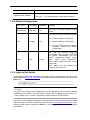
1.2.5 Login to the Switch
To access the switch web management function, open a web-browser and type in the
default address http://192.168.0.253 in the address field of the browser, then press the
Enter key.
Note:
To log in to the switch, the IP address of your PC should be set in the same subnet
addresses of the switch. For the first time, set your PC IP address as 192.168.0.x ("x"
is any number from 1 to 254, except 253), subnet mask as 255.255.255.0.
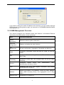
And then a login window will appear, as shown follows. Enter the default User Name
and Password. The default values are set in section 1.2.5 Default Configuration. Then
click the Login button or press the Enter key, so that you can see the switch system
information.
3
If you need to change the switch IP address at the first time, you can modify it through
RS232 console, or using telnet to login, you can refer to “KY-3000EM Industrial Switch
User Manual V1.2”.
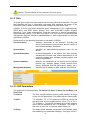
1.2.6 WEB Management Overview
This manual introduces the Industrial Switch User Manual V1.2industrial Ethernet
switches by the WEB interface, shown as follows.
Menu
Function Introduction
System
Information
Shows the device system information.
Advanced
Configuration
Enables or disables the main functions.
Port
Management
Set port configuration, Aggregation, Bandwidth and Mirroring
VLAN
Configures Port-based VLAN and 802.1Q VLAN, as well as
GARP.
QoS
Configures QoS, Scheduling Mechanism, Transmit Queues and
DSCP Map.
Forwarding
Configures unicast MAC and multicast MAC as well as IGMP
Snooping.
Security
Configures
Radius server,
port
authentication and storm control.
LLDP
Configures port LLDP and neighbor information, and checks
LLDP statistics information.
Statistics
Checks Port Status, Port Statistics, VLAN List, MAC Address
Table, IGMP Snooping Group, Link Aggregation and Fi Ring
Status
Spanning Tree
Configures STP and RSTP.
4
authentication,
MAC
Fi
Ring
Configures Fi Ring, coupling and the related timers.
Configuration
SNMP Manager
Configures SNMP accouts and traps.
RMON
Configures RMON event, alarm and history and checks RMON
statistics.
PTP
Administration
Configures device web interface language, IP, SNTP, SMTP.
Email alarm, relay alarm; checks system log; carries out ping
diagnosis; manages accounts; uses TFTP services; reboots and
resets the device and saves the configuration.
Logout
Logs out from the switch Web interface.
5
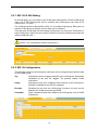
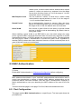
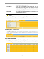
2 System Information
The device system information is shown as follows.
Through SNMP, you can configure the corresponding system name and system
location for each switch for convenient management.
6
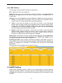
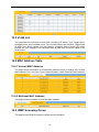
3 Advanced Configuration
IGMP Snooping, GVRP, STP, LACP, LLDP, 802.1X, Ky-Anillo and Modbus can be
enabled or disabled globally on this page.
7
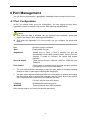
4 Port Management
You can set port configuration, aggregation, bandwidth and mirroring with this menu.
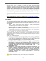
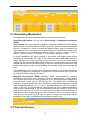
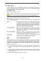
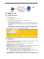
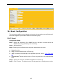
4.1 Port Configuration
At first, you should select a port for configuration. You can cofigure the port state,
negotiation, speed and duplex, flow control, MAC learning and MDI/MDIX.
Caution:
Only when the state is enbaled, can you configure the negotiation, speed and
duplex, flow control, MAC learning and MDI/MDIX.
Only when the negotiation is in Force mode, can you configure the speed and
duplex.
Port
Specifies a port to configure
State
Enable/disble the port
Negotiation
Selects Auto or Force, if Auto is selected, the port will
automatically use the best operating mode; while is Force is
selected, it needs to configure the speed and duplex
manually.
Speed & Duplex
There are four choices: 10M Half, 10M Full, 100M Half, and
100M Full.
Flow Control
If flow control is enabled on both the local and peer switches.
If congestion occurs on the local switch:
The local switch sends a message to notify the peer switch of stopping sending
packets to itself or reducing the sending rate temporarily.
The peer switch will stop sending packets to the local switch or reduce the sending
rate temporarily when it receives the message; and vice versa. By this way, packet
loss is avoided and the network service operates normally.
If it is off, the port runs at full speed.
Learning
Enable/disable learning function
MDI/MDIX
Three selections: Auto, MDI and MDIX.
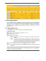
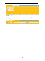
After clicking <Apply>, the lower part lists the port status.
8
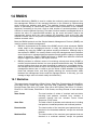
4.2 Port Aggregation
Link aggregation means aggregating several links together to form an aggregation
group, so as to implement outgoing/incoming load balance among the member ports in
the group and to enhance the connection reliability. Depending on different
aggregation modes, aggregation groups fall into three types: manual, static LACP, and
dynamic LACP.
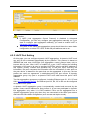
4.2.1 Aggregate Groups
KY-3000EMindustrial switches supports 13 link aggregation groups.
Configuration steps:
Step 1 Select Trunk ID. There are 13 groups(T1 ~ T13 );
Step 2 Specify the trunk name;
Step 3 Specify the trunk type;
Manual: a manual trunk can only be manually set or deleted; LACP can be
disabled.
Static:
a static LACP trunk can only be manually set or deleted; any port in a
static LACP trunk shall enable LACP protocol. When a static LACP
trunk is (manually) deleted, all ports of this trunk with “up” status will
generate one or more dynamic LACP trunks automatically.
Step 4 Select the ports as members of an aggregate group (2 ~ 8 ports);
Step 5 Click <Apply>, and then the link-aggregation Information will be listed at the
lower part.
Note: A trunk may be configured as a mirroring port, but it is not allowed to
configure a trunk as a monitoring port.
9
Caution:
If LACP (Link Aggregation Control Protocol) is disabled in Advanced
Configuration, you can only configure port aggregration manually, so If you
want to configure port aggregation statically, you need to enable LACP in
Advanced Configuration.
The ports of the same link-aggregration group should have the same basic
configuration, such as STP, QoS, VLAN and port attribute and so on.
4.2.2 LACP Port Setting
On this page, you can configure dynamic LACP aggregation. A dynamic LACP trunk
can only be set or deleted automatically by the protocol. This protocol is based on
IEEE802.3ad and uses LACPDUs (link aggregation control protocol data unit) to
interact with its peer. After LACP is enabled on a port, LACP notifies the following
information of the port to its peer by sending LACPDUs: priority and MAC address of
this system, priority, number and operation key of the port. Upon receiving the
information, the peer compares the information with the information of other ports on
the peer device to determine the ports that can be aggregated. In this way, the two
parties can reach an agreement in adding/removing the port to/from a dynamic
aggregation group. Any port in a dynamic LACP trunk shall have this port’s LACP
enabled.
Two link aggregation groups are configured, including Ethernet port 0/1, 0/3, 0/7 and
0/8 in 4.2.1 Aggregate Groups. So Ethernet port 0/2, 0/4, 0/5 to 0/6 can be configured
as dynamic LACP ports.
A dynamic LACP aggregation group is automatically created and removed by the
system. Users cannot add/remove ports to/from it. A port can participate in dynamic
link aggregation only when it is LACP-enabled. Ports can be aggregated into a
dynamic aggregation group only when they are connected to the same peer device
and have the same basic configuration (such as rate and duplex mode).
10
4.2.3 Aggregate Basic Setting
LACP determines the dynamic aggregation group members according to the priority of
the port ID on the end with the preferred device ID. The device ID consists of two-byte
system priority and six-byte system MAC address, that is, device ID = system priority +
system MAC address.
When two device KY-3000EM are compared, the system priorities are compared first,
and the system MAC addresses are compared when the system priorities are the
same. The device with smaller device ID will be considered as the preferred one.
There is a limit on the number of selected ports in an aggregation group. Therefore, if
the number of selected ports in an aggregation group exceeds the maximum member
port number supported by the device, the system will choose the ports with lower port
numbers as the member ports.
Set LACP system priority (from 1 to 65535).
4.2.4 LACP Status Setting
Set LACP port status as active or passive.
Passive
The port does not automatically send LACP protocol packets; it
responds only if it receives an LACP protocol packet from the peer
device.
Active
The port automatically sends LACP protocol packets.
A link having either one or two active LACP ports can perform dynamic LACP trunking.
If the two LACP ports connected are passive, they will not perform dynamic LACP
trunking as both ports are waiting for LACP protocol packet from the peer device.
Note:
The dynamic active LACP ports on this device can aggregate with the active or
passive LACP ports of the peer devices, but the passive LACP ports of this device
can only aggregate with the active LACP ports of the peer devices.
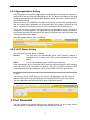
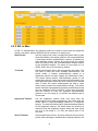
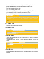
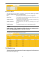
4.3 Port Bandwidth
You can configure the egress traffic limit on individual ports, so as to keep normal
network service. The bottom of the page will show the rate limit list.
11
Port
Select the port to configure
Egress
The desired egress rate limit to be configured. Choose “disabled” to
set the port with no egress rate limit, which means the port will run in
full speed for egress traffic. You can also select a specific egress rate
from the drop-down list for a port.
When completing the configuration, click <apply> to take effect. The lower part of this
page shows a full list of rate limit for each port.
Note: The Egress status of Ethernet 0/1, 0/3, 0/7 and 0/8 are displayed gray, they
cannot be condigured the egress rate, because they are aggregration ports.
Caution: Egress rate cannot be enabled on the aggregration ports.
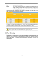
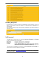
4.4 Port Mirroring
Port mirroring refers to the process of copying the packets received or sent by the
specified port to the destination port for packet analysis and monitoring. Generally, a
destination port is connected to a data detect device, which users can use to analyze
the mirrored packets for monitoring and troubleshooting the network, shown as the
following figure:
12
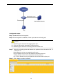
Configuration steps:
Step 1 Enable/disable mirroring state;
Step 2 If mirroring state is enabled, choose a port as the monitoring port;
Caution:
Step 3
Monitoring port cannot be link-aggregration port;
Only one port can be selected as monitoring port;
Monitoring port cannot be mirroring port at the same time.
Select the mirroring ports and whether the packets to be mirrored are Rx, Tx
or both Rx /Tx.
None: Means to mirror none packets on the port;
Rx Port: Means only to mirror the packets received by the port;
Tx Port: Means only to mirror the packets sent by the port;
Rx /Tx Port: Means to mirror the packets received and sent by the port.
Step 4 Click <Apply> to make it effective.
13
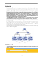
5 VLAN
The traditional Ethernet is a broadcast network, where all hosts are in the same
broadcast domain and connected with each other through hubs or switches. The hub is
a physical layer device without the switching function, so it forwards the received
packet to all ports. The switch is a link layer device which can forward the packet
according to the MAC address of the packet. However, when the switch receives a
broadcast packet or an unknown unicast packet whose MAC address is not included in
the MAC address table of the switch, it will forward the packet to all the ports except
the inbound port of the packet. In this case, a host in the network receives a lot of
packets whose destination is not the host itself. Thus, plenty of bandwidth resources
are wasted, causing potential serious security problems.
The traditional way to isolate broadcast domains is to use routers. However, routers
are expensive and provide few ports, so they cannot subnet the network particularly.
The virtual local area network (VLAN) technology is developed for switches to control
broadcast in LANs.
By creating VLANs in a physical LAN, you can divide the LAN into multiple logical
LANs, each of which has a broadcast domain of its own. Hosts in the same VLAN
communicate with each other as if they are in a LAN. However, hosts in different
VLANs cannot communicate with each other directly.
This managed switch supports 802.1Q VLAN and port-based VLAN. VLAN is in 802.1Q
mode in default configuration.
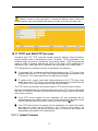
5.1 Advanced
This page globally sets the VLAN mode from the following: NO VLAN, port-based VLAN
and 802.1Q VLAN.
14
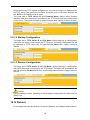
5.2 802.1Q VLAN
VLAN tags in the packets are necessary for the switch to identify packets of different
VLANs. The switch works at Layer 2 and it can identify the data link layer
encapsulation of the packet only, so you can add the VLAN tag field into only the data
link layer encapsulation if necessary.
In 1999, IEEE issues the IEEE 802.1Q protocol to standardize VLAN implementation,
defining the structure of VLAN-tagged packets.
In traditional Ethernet data frames, the type field of the upper layer protocol is
encapsulated after the destination MAC address and source MAC address, as shown
in the follow figure of Encapsulation format of traditional Ethernet frames.
DA refers to the destination MAC address, SA refers to the source MAC address, and
Type refers to the protocol type of the packet. IEEE 802.1Q protocol defines that a
4-byte VLAN tag is encapsulated after the destination MAC address and source MAC
address to show the information about VLAN.
As shown in the following figure of Format of VLAN tag, a VLAN tag contains four fields,
including TPID, priority, CFI, and VLAN ID.
TPID is a 16-bit field, indicating that this data frame is VLAN-tagged. By default, it
is 0x8100 in KY-3000EM Ethernet industrial switches.
Priority is a 3-bit field, referring to 802.1p priority. Refer to section “QoS & QoS
profile” for details.
CFI is a 1-bit field, indicating whether the MAC address is encapsulated in the
standard format in different transmission media.
VLAN ID is a 12-bit field, indicating the ID of the VLAN to which this packet
belongs. It is in the range of 0 to 4,095. Generally, 0 and 4,095 is not used, so the
field is in the range of 1 to 4,094.
VLAN ID identifies the VLAN to which a packet belongs. When the switch receives a
packet carrying no VLAN tag, it will encapsulate a VLAN tag with the default VLAN ID
of the inbound port for the packet, and the packet will be assigned to the default VLAN
of the inbound port for transmission.
Note:
Select 802.1Q VLAN from the VLAN Mode in 5.1 Advanced, so that you can enter
the 802.1Q VLAN configuration page.
15
5.2.1 802.1Q VLAN Setting
On this tab page, you can create a new VLAN group with specific VID and VLAN group
name. Up to 256 VLAN groups can be created; each VLAN group can have an ID
number from 1 to 4094.
The VLAN group with VLAN identifier (VID) of 1 is a default VLAN group. Each port is a
member of this group by default, and its value can be modified.
The lower part of this page lists all existing VLAN groups, as well as the information of
each VLAN group. Users can also modify or delete an existing VLAN group except the
default VLAN with VID 1.
Caution: It is not allowed to delete VLAN group 1.
5.2.2 802.1Q Configuration
This tab page configures a VLAN group; each port can be configured as a specific state
for this VLAN group:
Tag
Indicates the port is a tagged member of the VLAN group. All packets
forwarded by the port are tagged. The packets contain VLAN
information.
Untag
Indicates the port is an untagged VLAN member of the VLAN group.
Packets forwarded by the port are untagged.
Exclude
Excludes the port from the VLAN group. However, the port can be
added to the VLAN group through GVRP.
Forbidden
Does not allow the port to be added to the VLAN group, even if GVRP
indicates so.
16
5.2.3 802.1Q Port
This tab page configures 802.1Q VLAN port parameters:
Port : Specify the port to be configured.
PVID: Each port can have only one Port VLAN ID (PVID), an untagged Ethernet
package will be tagged a VID of PVID when arriving at the port. The default PVID is 1
for each port.
Link Type: Can choose Hybrid (by default), Access or Trunk from this drop-down list.
Access: An access port can belong to only one VLAN, and is generally used to
connect user PCs. Tag is deleted when transmitting packets.
Trunk: A trunk port can belong to more than one VLAN. It can receive/send
packets from/to multiple VLANs, and is generally used to connect another switch.
A trunk port can belong to multiple VLANs, but it can only be configured as
untagged in one VLAN. All packages are tagged, except when an egress package
is in a VLAN group with VID the same as PVID.
Hybrid: A hybrid port can belong to more than one VLAN. It can receive/send
packets from/to multiple VLANs, and can be used to connect either a switch or
user PCs. A Hybrid port is similar to a Trunk port, except it leaves the user a
flexibility of configuring each port as tagged or untagged.
Frame Type: Chooses how the port accepts Ethernet package. When Admit All is
selected, the port accepts all ingress packages; while Admit Only Tagged accepts
only tagged packages, and discards untagged ones.
VLAN Ingress Filter: When enabled, an Ethernet package is discarded if this port is
not a member of the VLAN with which this package is associated. When disabled (by
default), all packages are forwarded in accordance with the 802.1Q VLAN bridge
specification.
The lower part of this tab page lists the status of all ports.
5.3 GARP Setting
GARP VLAN registration protocol (GVRP) is an implementation of generic attribute
registration protocol (GARP). It maintains dynamic VLAN registration information and
propagates the information to other switches by adopting the same mechanism as that
of GARP.
17
After the GVRP feature is enabled on a switch, the switch receives the VLAN
registration information from other switches to dynamically update the local VLAN
registration information (including VLAN members, ports through which the VLAN
members can be reached, and so on). The switch also propagates the local VLAN
registration information to other switches so that all the switching devices in the same
switched network can have the same VLAN information. The VLAN registration
information includes not only the static registration information configured locally, but
also the dynamic registration information received from other switches.
Note:
Before configuring GARP, make sure to enable GVRP in 3 Advanced Configuration.
5.3.1 GARP
The information exchange between GARP members is completed by messages. The
messages performing important functions for GARP fall into three types: Join, Leave
and LeaveAll.
When a GARP entity expects other switches to register certain attribute
information of its own, it sends out a Join message.
When a GARP entity expects other switches to unregister certain attribute
information of its own, it sends out a Leave message.
Once a GARP entity starts up, it starts the LeaveAll timer. After the timer times
out, the GARP entity sends out a LeaveAll message.
The Join message and the Leave message are used together to complete the
un-registration and re-registration of information. Through message exchange, all the
attribute information to be registered can be propagated to all the switches in the same
switched network.
GARP uses the following timers:
Join Timer: To transmit the Join messages reliably to other entities, a GARP entity
sends each Join message two times. The Join timer is used to define the interval
at which each Join message is sent. It ranges from 10 to 2147483640 milliseconds,
and it must be integral multiple of 10. It is 200 milliseconds by default.
Leave Timer: When a GARP entity expects to unregister a piece of attribute
information, it sends out a Leave message. Any GARP entity receiving this
message starts its Leave timer, and unregisters the attribute information if it does
not receives a Join message again before the timer times out. It ranges from 30 to
2147483640 milliseconds, and it must be integral multiple of 10. It is 600
milliseconds by default.
LeaveAll Timer: Once a GARP entity starts up, it starts the LeaveAll timer, and
sends out a LeaveALL message after the timer times out, so that other GARP
entities can re-register all the attribute information on this entity. After that, the
entity restarts the LeaveAll timer to begin a new cycle. It ranges from 40 to
2147483640 milliseconds, and it must be integral multiple of 10. It is 1000
milliseconds by default.
Caution: It must satisfy 2*(join_time) < leave_time < leaveall_time.
18
5.3.2 GVRP
GVRP (GARP VLAN Registration Protocol) is an implementation of GARP (generic
attribute registration protocol). GVRP allows the switch to automatically add or remove
the VLANs via the dynamic VLAN registration information and propagate the local
VLAN registration information to other switches, without having to individually configure
each VLAN.
GVRP has the following three port registration modes: Normal, Fixed, and Forbidden.
Normal: In this mode, a port can dynamically register/deregister a VLAN and
propagate the dynamic/static VLAN information.
Fixed: In this mode, a port cannot register/deregister a VLAN dynamically. It only
propagates static VLAN information. That is, a trunk port only permits the packets
of manually configured VLANs in this mode even if you configure the port to permit
the packets of all the VLANs.
Forbidden: In this mode, a port cannot register/deregister VLANs. It only
propagates VLAN 1 information. That is, a trunk port only permits the packets of
the default VLAN (namely VLAN 1) in this mode even if you configure the port to
permit the packets of all the VLANs.
Configuration Steps:
Step 1 Select a specific port for setting;
Step 2 Enable or disable the GVRP function on the port;
Step 3 Select the Registration Type for the selected port.
The lower part lists the GVRP attribute of all ports.
Caution:
If a port is configured in Ky-Anillo, it cannot be enabled GVRP
The port to configure GVRP must be a trunk port.
19
;
5.3.3 GMRP
GMRP is a concrete application based on GARP. It avoids the network resources
waste for the broadcast of multicast by taking use of GARP working mechanism to
maintain the information of multicast MAC form in switchboard. All the switchboards
which support GMRP can receive the multicast MAC address registration information
from other switchboards, then dynamically update the corresponding information for
local system, including indicating which current ports have these information already.
Meanwhile, all these switchboards can transmit the local multicast MAC address
registration information to other switchboards as well.
The configuration steps are as follows:
Step 1 Enable global GMRP
Step 2 Select Ethernet port
Step 3 Enable or disable the GMRP function of port
20
6 QoS
In data communications, Quality of Service (QoS) is the ability of a network to provide
differentiated service guarantees for diversified traffic in terms of bandwidth, delay, jitter,
and drop rate.
On traditional IP networks, devices treat all packets equally and handle them using the
first in first out (FIFO) policy. All packets share the resources of the network and
devices. How many resources the packets can obtain completely depends on the time
they arrive. This service is called best-effort. It delivers packets to their destinations as
possibly as it can, without any guarantee for delay, jitter, packet loss ratio, reliability and
so on.
The Internet has been growing along with the fast development of networking
technologies. More and more users take the Internet as their data transmission
platform to implement various applications. Besides traditional applications such as
WWW, e-mail and FTP, network users are experiencing new services, such as
tele-education,
telemedicine,
video
telephone,
video
conference
and
Video-on-Demand (VoD). The enterprise users expect to connect their regional
branches together through VPN technologies to carry out operational applications, for
instance, to access the database of the company or to monitor remote devices through
Telnet. These new applications have one thing in common, that is, they all have
special requirements for bandwidth, delay, and jitter. For instance, videoconference
and VoD need large bandwidth, low delay and jitter. As for mission-critical applications,
such as transactions and Telnet, they may not require large bandwidth but do require
low delay and preferential service during congestion.
6.1 QoS Configuration
6.1.1 General Priority
Enable of disable the priority of the switch.
6.1.2 Port QoS Configuration
This tab page sets QoS parameters of each port. For a selected port, set the 802.1P,
Port-based Priority with DSCP enabled or disabled, the Default Priority can be set from
0 to 7.
802.1P
Enable or disable 802.1P. 802.1p priority lies in Layer 2
packet headers and is applicable to occasions where the
Layer 3 packet header does not need analysis but QoS must
be assured at Layer 2.
Port-based Priority
There is 8 priorities from 0 to 7.
DSCP
Enable or disable DSCP
The lower part of QoS Configuration tab page lists the default priority of all ports and
the state of DSCP.
21
6.2 Scheduling Mechanism
This page sets the queue scheduling algorithm and related parameters.
Scheduling Mechanism: Can be set to Strict Priority or Weighted Round-Robin
(WRR)
Strict Priority: SP queue-scheduling algorithm is specially designed for critical service
applications. An important feature of critical services is that they demand preferential
service in congestion in order to reduce the response delay. Assume that there are
eight output queues on the port and the preferential queue classifies the eight output
queues on the port into eight classes, which are queue 7, queue 6, queue 5, queue 4,
queue 3, queue 2, queue 1, and queue 0. Their priorities decrease in order.
In queue scheduling, SP sends packets in the queue with higher priority strictly
following the priority order from high to low. When the queue with higher priority is
empty, packets in the queue with lower priority are sent. You can put critical service
packets into the queues with higher priority and put non-critical service (such as e-mail)
packets into the queues with lower priority. In this case, critical service packets are sent
preferentially and non-critical service packets are sent after critical service groups are
sent.
The disadvantage of SP queue is that: if there are packets in the queues with higher
priority for a long time in congestion, the packets in the queues with lower priority will
be “starved” because they are not served.
Weighted Round-Robin (WRR) (8:4:2:1): WRR queue-scheduling algorithm
schedules all the queues in turn and every queue can be assured of a certain service
time. Assume there are four priority queues on a port. WRR configures a weight value
for each queue, which are Q1, Q2, Q3 and Q4. The weight value indicates the
proportion of obtaining resources. On a 150 M port, configure the weight value of WRR
queue-scheduling algorithm to 8, 4, 2 and 1 (corresponding to Q1, Q2, Q3 and Q4 in
order). In this way, the queue with the lowest priority can get 10 Mbps bandwidth at
least, and the disadvantage of SP queue-scheduling that the packets in queues with
lower priority may not get service for a long time is avoided. Another advantage of
WRR queue is that: though the queues are scheduled in order, the service time for
each queue is not fixed; that is to say, if a queue is empty, the next queue will be
scheduled. In this way, the bandwidth resources are made full use.
6.3 Transmit Queues
22
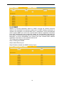
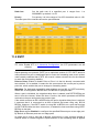
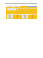
This page sets the 802.1p priority to local precedence mapping. The following table
lists the default mapping between 802.1p priority and local precedence:
If the map between the default 802.1p priority and the local precedence cannot satisfy
the user’s need, you can modify the map from 802.1p priority to local precedence to
change the relationship between 802.1p priority and transmit queues. The following
table lists the map from 802.1p priority to local precedence.
802.1p priority
0
1
2
3
4
5
6
7
Local precedence
Q0
Q0
Q1
Q1
Q2
Q2
Q3
Q3
You can modify the transmit queues here. Click <Apply> to make it take effect. If there
is no modification for the queues, directly click <Apply>.
6.4 DSCP Map
This page sets the mapping between the DSCP value and the local precedence priority.
DSCP (Differentiated Services CodePoint) priority ranges from 0 to 63.
23
7 Forwarding
KY-3000EM industrial switch has unicast MAC address forwarding and multicast MAC
address forwarding, the introduction is followed.
7.1 Unicast MAC Address
MAC address forwarding table: the device forwards the packets to the corresponding
port according to the packet destination MAC address. The MAC address forwarding
table reflects the relationship between the MAC address and the forwarding port.
A MAC address table is maintained for packet forwarding. Each entry in this table
indicates the following information:
The MAC address of a connected network device
The interface to which the device is connected
The VLAN to which the interface belongs
Unicast MAC address configuration is for the unicast forwarding mode.
7.1.1 MAC Address
On this page, you can add an entry in MAC table.
VID
Unicast MAC Address
Port
Type
Specifies a VLAN group with which the MAC address
corresponds.
Specifies the destination MAC address.
Specifies the port of the outbound interface.
Choose among Dynamic, Static and Blackhole.
Static MAC address entry: Also known as permanent MAC address entry. This
type of MAC address entries are added/removed manually and cannot age out by
themselves. Using static MAC address entries can reduce broadcast packets
remarkably and are suitable for networks where network devices seldom change.
Dynamic MAC address entry: This type of MAC address entries age out after the
configured aging time. They are generated by the MAC address learning
mechanism or configured manually.
Blackhole MAC address entry: This type of MAC address entries are configured
manually. A switch discards the packets destined for or originated from the MAC
addresses contained in blackhole MAC address entries.
The lower part lists all existing unicast MAC addresses, as well as the information of
each unicast MAC address. The user can also modify or delete an existing unicast
MAC address. Dynamic MAC address will also be shown on the Dynamic MAC
Address page.
Caution:
The port must be a member of this VLAN.
The port should not be a member of a trunk group.
24
7.1.2 Dynamic Unicast MAC
This page lists all dynamic unicast MAC addresses, including learned by the switch
and added manually. An entry can be deleted. If the time is out, it will refresh the list
automatically. The timer is 300 seconds fixedly.
7.2 Multicast MAC Address
As a technique coexisting with unicast and broadcast, the multicast technique
effectively addresses the issue of point-to-multipoint data transmission. By allowing
high-efficiency point-to-multipoint data transmission over a network, multicast greatly
saves network bandwidth and reduces network load.
With the multicast technology, a network operator can easily provide new value-added
services, such as live Webcasting, Web TV, distance learning, telemedicine, Web radio,
real-time videoconferencing, and other bandwidth- and time-critical information
services.
When some hosts on the network need multicast information, the information sender,
or multicast source, sends only one copy of the information. Multicast distribution trees
are built through multicast routing protocols, and the packets are replicated only on
nodes where the trees branch.
25
The advantages of multicast are summarized as follows:
Over unicast: As multicast traffic flows to the node the farthest possible from the
source before it is replicated and distributed, an increase of the number of hosts
will not increase the load of the source and will not remarkably add to network
resource usage.
Over broadcast: As multicast data is sent only to the receivers that need it,
multicast uses the network bandwidth reasonably and enhances network security.
In addition, data broadcast is confined to the same subnet, while multicast is not.
A multicast group is a multicast receiver set identified by an IP multicast address.
Hosts join a multicast group to become members of the multicast group, before they
can receive the multicast data addressed to that multicast group. Typically, a multicast
source does not need to join a multicast group. An information sender is referred to as
a multicast source. A multicast source can send data to multiple multicast groups at the
same time, and multiple multicast sources can send data to the same multicast group
at the same time. All hosts that have joined a multicast group become members of the
multicast group.
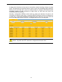
This page sets multicast MAC address entries. Each multicast MAC address entry
contains multicast address, forward ports, and VID.
VID
Specifies the VLAN group of which the forwarding ports
are members.
Multicast MAC Address
Multicast MAC address, in the form of xx-xx-xx-xx-xx-xx.
Member
Specifies forwarding ports for the specified multicast
MAC group address. One or more ports can be added
as the member.
The lower part of this page lists all existing multicast MAC addresses, as well as the
information of each multicast MAC address. The user can also modify or delete an
existing multicast MAC address.
26
Caution:
Multicast source maybe doesn’t belong to the multicast group, that is to say, it is
not necessarily the receiver of multicast data;
A multicast source can transmit packets to multiple multicast groups at the same
time, while several multicast source can also send packets to the same multicast
group.
As shown in the following figure, the port 0/2 in VLAN 1 can send packets to the
multicast address 01-ac-2b-4e-32-55.
Caution: Multicast MAC address cannot configured on Link-aggregation ports.
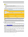
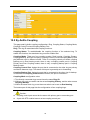
7.3 IGMP Snooping Configuration
Note: Before configuring IGMP Snooping, first enable IGMP Snooping in 3
Advanced Configuration.
Internet Group Management Protocol Snooping (IGMP Snooping) is a multicast
constraining mechanism that runs on Layer 2 devices to manage and control multicast
groups.
By listening to and analyzing IGMP messages, a Layer 2 device running IGMP
Snooping establishes mappings between ports and multicast MAC addresses and
forwards multicast data based on these mappings.
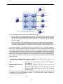
As shown in the following figure, when IGMP Snooping is not running on the device,
multicast packets are broadcast to all devices at Layer 2. When IGMP Snooping is
running on the switch, multicast packets for known multicast groups are multicast to the
receivers, rather than broadcast to all hosts, at Layer 2.
27
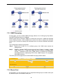
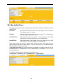
7.3.1 IGMP Snooping
On this page, you can enable IGMP Snooping feature for a VLAN group. By default,
the IGMP Snooping feature is disabled.
With the wide use of multicast, IGMPv3 is used more and more. It adds the multicast
source filtering function, which enabled the receiver be able to specify the multicast
group to join in as well as specify the multicast source to receive multicast information
from.
The configuration steps are as follows:
Step 1
Specify the VLAN ID of a multicast group, the VLAN name cannot be
changed here.
Step 2
Enable or disable IGMP Snooping on the field of Status, if enable it, select
IGMP version 2 or 3. Until now, IGMP has three versions: including IGMP
Version 1 (defined by RFC1112), IGMP Version 2 (defined by RFC2236),
and IGMP Version 3 (defined by RFC 3376). IGMP Version 2 is compatible
with IGMP Version 1.
The lower part of this page lists all VLAN IGMP Snooping feature status.
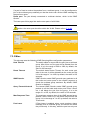
7.3.2 Route Port
On this page, you can configure a port in a specified VLAN group as a static router port.
By default, a port is not a static router port.
28
If a port is fixed to receive the packets from a multicast group, it can be configured to
join in the multicast group statically, so that the device can receive IGMP message by
the port from router.
Route port: The port directly connected to multicast devices, which is the IGMP
Querier.
The lower part of this page lists static router ports of all VLANs.
Caution: the router port should be within the VLAN. Please refer to 5 VLAN.
7.3.3 Misc
This tab page sets the following IGMP Snooping Misc configuration parameters:
Host Timeout
The switch starts for a port after the port joins a multicast
group. After it time out, the port will be deleted from the
group. It is in the range of 200 to 1000; by default, the
value is 260 seconds.
Route Timeout
The switch starts Router Timeout for each router port
when it time out, it will be deleted from the router port list.
It is in the range of 1 to 1000; by default, the value is 105
seconds.
IGMP Querier
IGMP Querier sends IGMP general query packets to all
the hosts and router ports in the network segment to
check the multicast group members. By default, IGMP
Querier is disabled.
Query Transmit Interval
The interval IGMP Querier sends IGMP general query
packets to all the hosts and router ports. After it times
out, it will delete the port form the group. It is in the
range of 1 to 255, by default, the value is 125 seconds.
Max Response Time
The maximum response time of the IGMP general query
packets. After it times out, it will delete the port form the
group. It is in the range of 1 to 25, by default, the value is
10 seconds.
Fast Leave
If Fast Leave is enabled, when a port receives a leave
message from a multicast group, the switch will delete
the port directly. In this way, when the port has only one
29
user, it can save bandwidth.
30
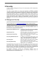
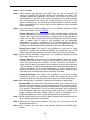
8 Security
It mainly introduces Management Security, Port Authentication, MAC Authentication
and Storm Control.
The 802.1x protocol (802.1x for short) was developed by IEEE802 LAN/WAN
committee to address security issues of wireless LANs. It was then used in Ethernet as
a common access control mechanism for LAN ports to address mainly authentication
and security problems. 802.1x is a port-based network access control protocol. It
authenticates and controls devices requesting for access in terms of the ports of LAN
access control devices. With the 802.1x protocol employed, a user-side device can
access the LAN only when it passes the authentication. Those fail to pass the
authentication are denied when accessing the LAN, as if they are disconnected from
the LAN.
8.1 Management Security
Note: Enable 802.1x in 3 Advanced Configuration before configuring Radius.
This page configures the 802.1x system as follows: Authentication RADIUS Server IP,
Authentication Port, Authentication Shared Key, Accounting RADIUS Server IP,
Accounting Port and Accounting Shared Key.
Authentication RADIUS Server IP
IP address of the radius server to be used, a
valid unicast address in dotted decimal notation;
the default value is 192.168.0.234.
Authentication Port
UDP port number of the radius server, ranging
from 0 to 65535; the default value is 1812.
Authentication Shared Key
Sets a shared key for radius messages. String
length is 1 to 15 characters.
Accounting RADIUS Server IP
IP address of accounting radius server to be
used, a valid unicast address in dotted decimal
notation; the default value is 192.168.0.234.
Accounting Port
UDP port number of the radius server, ranging
from 0 to 65535; the default value is 1813.
Accounting Shared Key
Sets a shared key for accounting radius. String
length is from 1 to 15 characters.
The authentication server system is an entity that provides authentication service to the
authenticator system. Normally in the form of a RADIUS server, the authentication
server system serves to perform AAA (authentication, authorization, and accounting)
services to users. It also stores user information, such as user name, password, the
VLAN a user belongs to, priority, and the ACLs (access control list) applied.
Set RADIUS configuration, including the authentication RADIUS server IP,
authentication port, authentication shared key, accounting RADIUS server IP,
accounting port and accounting shared key.
31
8.2 Port Authentication
IEEE 802.1x authentication system uses extensible authentication protocol (EAP) to
exchange information between supplicant systems and the authentication servers.
When a supplicant system passes the authentication, the authentication server passes
the information about the supplicant system to the authenticator system. The
authenticator system in turn determines the state (authorized or unauthorized) of the
controlled port according to the instructions (accept or reject) received from the
RADIUS server.
802.1x Authentication Procedure:
A supplicant system launches an 802.1x client to initiate an access request by
sending an EAPoL-start packet to the switch, with its user name and password
provided. The 802.1x client program then forwards the packet to the switch to start
the authentication process.
Upon receiving the authentication request packet, the switch sends an
EAP-request/identity packet to ask the 802.1x client for the user name.
The 802.1x client responds by sending an EAP-response/identity packet to the
switch with the user name contained in it. The switch then encapsulates the packet
in a RADIUS Access-Request packet and forwards it to the RADIUS server.
Upon receiving the packet from the switch, the RADIUS server retrieves the user
name from the packet, finds the corresponding password by matching the user
name in its database, encrypts the password using a randomly-generated key, and
sends the key to the switch through an RADIUS access-challenge packet. The
switch then sends the key to the 802.1x client.
Upon receiving the key (encapsulated in an EAP-request/MD5 challenge packet)
from the switch, the client program encrypts the password of the supplicant system
with the key and sends the encrypted password (contained in an
EAP-response/MD5 challenge packet) to the RADIUS server through the switch.
(Normally, the encryption is irreversible.)
The RADIUS server compares the received encrypted password (contained in a
RADIUS access-request packet) with the locally-encrypted password. If the two
match, it will then send feedbacks (through a RADIUS access-accept packet and
an EAP-success packet) to the switch to indicate that the supplicant system is
authenticated.
The switch changes the state of the corresponding port to accepted state to allow
the supplicant system to access the network.
The supplicant system can also terminate the authenticated state by sending
EAPoL-Logoff packets to the switch. The switch then changes the port state from
accepted to rejected.
32
8.2.1 802.1x Port
This tab page sets 802.1x port enabling, port control, re-authentication and Guest
VLAN for a specified Ethernet port. There are three choices for Port Control: Auto,
Force Authorized and Force Unauthorized.
Configuration Steps:
Step 1 Specify the port to configure
Caution: The port to configure authentication cannot be link-aggregation port.
Step 2 Enable or disable the 802.1x authentication function
Step 3 If 802.1x is enabled, you can further configure port control, re-authentication
and Guest VLAN;
Auto
Specify to operate in auto access control mode. When one
port operates in this mode, all the unauthenticated hosts
connected to it are unauthorized. In this case, only EAPoL
packets can be exchanged between the switch and the hosts.
And the authenticated hosts connected to the port are
authorized to access the network resources.
Force Authorized
Specify to operate in authorized-force access control mode.
When one port operates in this mode, all the hosts
connected to it can access the network resources without
the need of authentication.
Force Unauthorized
Specify to operate in unauthorized-force access control
mode. When one port operates in this mode, the hosts
connected to it cannot access the network resources.
Guest VLAN
A guest VLAN can be enabled for each IEEE 802.1x port on
the switch to provide limited services to the clients.
Step 4
Enable or disable Re-authentication
Step 5
Enable or disable Guest VLAN
The Guest VLAN function enables supplicant systems that that are not authenticated to
access network resources in a restrained way. It enables supplicant systems that do
not have 802.1x client installed to access specific network resources. It also enables
supplicant systems that are not authenticated to upgrade their 802.1x client programs.
With this function enabled:
After the maximum number retries have been made and there are still ports that
have not sent any response back, the switch will then add these ports to the Guest
VLAN.
Users belonging to the Guest VLAN can access the resources of the Guest VLAN
without being authenticated. But they need to be authenticated when accessing
external resources.
The lower part of this page lists all 802.1x port status.
33
8.2.2 802.1x Misc
In 802.1 x authentication, the following timers are used to ensure that the supplicant
system, the switch, and the RADIUS server interact in an orderly way.
Quiet Period
Set the quiet-period, when a supplicant system fails to pass
the authentication; the switch quiets for the set period before
it processes another authentication request re-initiated by
the supplicant system. During this quiet period, the switch
does not perform any 802.1x authentication-related actions
for the supplicant system. The value is in the range of 1 to
65535, and is set to 60 seconds by default.
Tx Period
Set the transmission timer, and is triggered in two cases. The
first case is when the client requests authentication, the
switch sends a unicast request/identity packet to a
supplicant system and then triggers the transmission timer.
The switch sends another request/identity packet to the
supplicant system if it does not receive the reply packet from
the supplicant system when this timer times out. The second
case is when the switch authenticates the 802.1x client
which cannot request for authentication actively. The switch
sends multicast request/identity packets periodically through
the port enabled by 802.1x function. In this case, this timer
sets the interval to send the multicast request/identity
packets. It is in the range of 1 to 65535; the default value is
30 seconds.
Supplicant Timeout:
Set the supplicant system timer, this timer sets the
supp-timeout period and is triggered by the switch after the
switch sends a request/challenge packet to a supplicant
system. The switch sends another request/challenge packet
to the supplicant system if the switch does not receive any
response from the supplicant system when this timer times
out. It is in the range of 1 to 300; the default value is 30
seconds.
Server Timeout
Set the radius server timer, this timer sets the server-timeout
period. After sending an authentication request packet to the
34
radius server, a switch sends another authentication request
packet if it does not receive any response from the radius
server when this timer times out. It is in the range of 1 to 300;
the default value is 30 seconds.
Max Request Count
Set the maximum number of times that a switch sends
authentication request packets to a user. It is in the range of
1 to 10, and the default value is 2.
Reauth Period
Set re-authentication interval in second. After this timer
expires, the switch indicates: 802.1x re-authentication. It is in
the range of 60 to 7200; the default value is 60 seconds.
Guest VLAN
Can choose a guest VLAN on the switch to provide limited
services to clients, such as downloading. By default, there is
none guest VLAN.
When enabling a guest VLAN on an IEEE 802.1x port, the switch assigns the client
port to a guest VLAN in case that the switch does not receive any response to its EAP
request/identity frame, or EAPOL packets are not sent by the client. The switch allows
the client that is failed in authentication to access the guest VLAN, regardless of
whether EAPOL packets have been detected. However, access to external ports out of
guest VLAN still needs to be authorized.
8.3 MAC Authentication
Note:
Enable MAC Authenticantion in 3 Advanced Configuration before configuring .
MAC address authentication is port- and MAC address-based authentication used to
control user permissions to access a network. MAC address authentication can be
performed without client-side software. With this type of authentication employed, a
switch authenticates a user upon detecting the MAC address of the user for the first
time.
There are three tab pages in this page: Port Conf, Misc and Authenticate Infor.
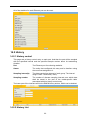
8.3.1 Port Configuration
This page enables MAC Authentication on a specific port. The lower part shows the
port status list.
35
Caution: Link-aggregation port cannot be configured MAC authenticaiton.
8.3.2 Misc
MAC authentication process is affected by the following timers:
Offline detect time
Sets the time interval for a switch to test whether a user goes
offline. Upon detecting a user is offline, a switch notifies the
RADIUS server of the user to trigger the RADIUS server to
stop the accounting on the user. The value ranges from 1 to
65535, and the default value is 300 seconds.
Quiet Period
Sets the quiet period for a switch. After a user fails to pass
the authentication performed by a switch, the switch quiets
for a specific period (the quiet period) before it authenticates
users again. The value ranges from 1 to 3600, and the
default value is 60 seconds.
Server Timeout
Sets the time interval the switch waits for a response, when
there is a connection request from the authentication server
to the client. The value ranges from 1 to 65535, and the
default value is 100 seconds.
8.3.3 Authentication Information
This page lists all the MAC authentication information including MAC Address, From
Port, and Authenticate state.
8.4 Storm Control
36
Traffic storm will be generated when there are multiple broadcast / multicast / DLF
(Destination Lookup Failed) packets passing through a port, thus it will lead to traffic
congestion. If the transmission rate of the three kind packets exceeds the set
bandwidth, the packets will be automatically discarded to avoid network broadcast
storm.
This page sets thresholds of the specified Traffic Type.
Specify the traffic Type can be selected from: None, Broadcast, Broadcast + Multicast,
and Broadcast + Multicast + DLF Multicast. If “None” is selected, it means that storm
control is disabled. And specify the limited rate. As to the unknown DA unicast, there
are two ways to deal with: discard and forward.
37
9 LLDP
Note: Enable LLDP in 3 Advanced Configuration.
In a heterogeneous network, it is important that different types of network devices from
different vendors can discover one another and exchange configuration for
interoperability and management sake. Therefore, a standard configuration exchange
platform was created.
The IETF drafted the Link Layer Discovery Protocol (LLDP) in IEEE 802.1AB. The
protocol operates on the data link layer to exchange device information between
directly connected devices. With LLDP, a device sends local device information
(including its major functions, management IP address, device ID, and port ID) as TLV
(type, length, and value) triplets in Link Layer Discovery Protocol Data Units (LLDPDUs)
to the directly connected devices, and at the same time, stores the device information
received in LLDPDUs sent from the LLDP neighbors in a standard management
information base (MIB). It allows a network management system to fast detect Layer-2
network topology change and identify what the change is.
9.1 Management LLDP
9.1.1 Configuration
This page configures LLDP for a specified Ethernet port.
Configuration Steps:
Step 1
Specify the port to configure LLDP;
Step 2
Enable or disable LLDP on the port;
Step 3
Specify the LLDP status: Disabled, Tx and Rx, Tx Only and Rx Only;
Step 4
Specify the encapsulation format: Ethernet II and SNAP.
LLDP uses LLDPDUs to exchange information. An LLDPDU comprises multiple type,
length, and value (TLV) sequences. Each carries a specific type of device information,
as shown in the flowing LLDPDU encapsulation format figure.
An LLDPDU can carry up to 28 types of TLVs. Mandatory TLVs include Chassis ID
TLV, Port ID TLV, Time To Live TLV, and End of LLDPDU TLV. Other TLVs are
optional.
LLDP sends device information in LLDP data units (LLDPDUs). LLDPDUs are
encapsulated in Ethernet II or SubNetwork Access Protocol (SNAP) frames.
(1) Ethernet II-encapsulated LLDPDU format
38
Field
Destination
address
Description
MAC The MAC address to which the LLDPDU is advertised. It is
fixed to 0x0180-C200-000E, a multicast MAC address.
The MAC address of the sending port. If the port does not
Source MAC address
have a MAC address, the MAC address of the sending
bridge is used.
The Ethernet type for the upper layer protocol. It is
Type
0x88CC for LLDP.
Data
LLDP data unit (LLDPDU)
Frame check sequence, a 32-bit CRC value used to
FCS
determine the validity of the received Ethernet frame
(2) SNAP-encapsulated LLDPDU format
Field
Destination
address
Description
MAC The MAC address to which the LLDPDU is advertised. It is
fixed to 0x0180-C200-000E, a multicast MAC address.
The MAC address of the sending port. If the port does not
Source MAC address
have a MAC address, the MAC address of the sending
bridge is used.
The SNAP type for the upper layer protocol. It is
Type
0xAAAA-0300-0000-88CC for LLDP.
Data
LLDPDU
Frame check sequence, a 32-bit CRC value used to
FCS
determine the validity of the received Ethernet frame
When Ethernet II encapsulation format is adopted, LLDPDUs sent from the port with
LLDP enabled will be encapsulated with Ethernet II format, and the device will only
deal with the LLDPDUs encapsulated with the same encapsulation format. So is for the
SNAP-encapsulated LLDPDU.
39
LLDPDU encapsulation format is Ethernet II by default. If the neighbor devices
encapsulates LLDPDU with SNAP format, the user can change the LLDPDU
encapsulation format to SNAP to maintain the normal communication with neighbor
devices.
LLDP can operate in one of the following modes:
Disabled mode
Tx and Rx mode
Tx Only mode
Rx Only mode
A port in this mode does not send or receive LLDPDUs.
A port in this mode sends and receives LLDPDUs.
A port in this mode only sends LLDPDUs.
A port in this mode only receives LLDPDUs.
When the LLDP operating mode of a port takes change, its LLDP protocol state
machine will re-initialize. To prevent LLDP from being initialized too frequently during
times of frequent operating mode change, you can configure a re-initialization delay.
With this delay configured, a port must wait for the specified interval before it can
initialize LLDP after the LLDP operating mode changes.
Transmitting LLDPDUs
An LLDP-enabled port operating in “Tx and Rx” mode or “Tx Only” mode sends
LLDPDUs to its directly connected devices both periodically and when the local
configuration changes. To prevent the network from being overwhelmed by LLDPDUs
during times of frequent local device information change, an interval is introduced
between two successive LLDPDUs.
This interval is shortened to 1 second in either of the following two cases:
A new neighbor is discovered, in other words, a new LLDPDU is received carrying
device information new to the local device.
The LLDP operating mode of the port changes from “Disabled” /”Rx Only” to “Tx
and Rx” or “Tx Only”.
This is the fast sending mechanism of LLDP. This feature sends a specific number of
LLDPDUs at the 1-second interval to help LLDP neighbors discover the local device as
soon as possible. Then, the normal LLDPDU transmit interval resumes.
Receiving LLDPDUs
An LLDP-enabled port operating in “Tx and Rx” mode or “Rx Only” mode checks the
validity of TLVs carried in every received LLDPDU. If valid, the information is saved
and an aging timer is set for it based on the time to live (TTL) value in the Time To Live
TLV carried in the LLDPDU. If the TTL value is zero, the information is aged out
immediately.
The lower part of this page lists the LLDP status for all ports.
40
Caution: The port should not be a member of a trunk group.
9.1.2 TLVs
TLVs are type, length, and value sequences that carry information elements. The type
field identifies the type of information, the length field measures the length of the
information field in octets, and the value field contains the information itself.
LLDPDU TLVs fall into these categories: basic management TLVs, organizationally
(IEEE 802.1 and IEEE 802.3) specific TLVs, and LLDP-MED (media endpoint
discovery) TLVs. Basic management TLVs are essential to device management.
Organizationally specific TLVs and LLDP-MED TLVs are used for enhanced device
management; they are defined by standardization or other organizations and thus are
optional to LLDPDUs.
Decide which of the following information is included in LLDPDU.
Port Description
Identifies information of the interface, including the
name of manufacturer, product name, and the version of
the interface hardware & software.
System Name
Identifies the administratively-assigned name for the
device.
System Description
A textual description of the device, this value typically
includes the full name and version identification of the
system’s hardware type, software operating system, and
networking software.
System Capability
identifies the capabilities of the device and its primary
function (e.g. repeater, Bridge, WLAN, Access Point,
Router, Telephone, DOCSIS cable device, Station, etc.)
Management Address
Identifies the IP address or MAC address of the device.
9.1.3 LLDP Parameters
This page sets LLDP parameters: TX Interval, Tx Hold, Tx Delay, Re-init Delay, and
Fast Count.
Tx Interval
The time interval between sending LLDP packets, its range
is from 5 to 32768 seconds. The default value is 30 seconds.
Tx Hold
TTL multiplier. TTL of TLV carried in LLDPDU is used to set
the aging time on the neighbor device. Since TTL of TLV =
TTL multiplier × Tx Interval, the aging time on the neighbor
device can be adjusted by the TTL multiplier. The range of
this value is from 2 to 10, and the default value is 4.
Tx Delay
The delay period between successive LLDP packets which
are initiated by port parameter changes. The range is from 1
41
to 8192, and the default value is 2.
Re-init Delay
in the case of LLDP Status mode changes, the port will
initialize the protocol state machine, and the switch will need
to wait for Re-init Delay to be able to start the next
initialization. The range of this value is from 1 to 10 seconds,
and the default value is 2.
Fast Count
The number of fast sending packets. It is in the range of 1 to
10, and the default value is 3.
Caution:
Tx Interval and Tx Delay both should be smaller than TTL; otherwise it will cause the
neighbor device be unable to receive the LLDPDU from the current device after aging.
9.2 Neighbor Information
This page shows the Local Port, Chassis ID of a local device, and the Remote Port ID,
System name, Port description, System Capabilities, and Management Address of a
neighbor device.
9.3 LLDP Statistics
This page shows the statistics of Tx Frames, Rx Frames, Rx Error Frames, Discarded
Frames, TLVs discarded, TLVs unrecognized, Org.TLVs discarded, and Age out packet
counts of LLDP packets on each Ethernet port.
42
10 Statistics
It shows the following items:
10.1 Port Status
This page shows the State, Media, Link, Negotiation, Speed & Duplex, Flow Control,
Learning and MDI/MDIX of each Ethernet port.
10.2 Port Statistics
This page shows the TxGoodPkts, TxBadPkts, RxGoodPkts, RxBadPkts, TxAbort,
Collision, and DropPkt of each Ethernet port.
TxGoodPkts
The total number of outgoing normal packets on the port,
including outgoing normal packets and normal pause frames
TxBadPkts
The total byte number of outgoing error frames
RxGoodPkts
The total number of incoming normal packets on the port,
including incoming normal packets and normal pause frames
RxBadPkts
The total number of incoming error frames
TxFCSErr
The number of FCS (Frame Check (Checking) Sequence)
packets
Collision
The number of detected collisions
DropPkt
The number of packets dropped for various reasons
43
10.3 VLAN List
This page lists the information of all VLANs, including VID, Name, Type, Tagged ports,
Untagged ports, and Forbidden ports. Type includes Static and Dynamic; Tagged lists
all ports from which packets are sent tagged; Untagged lists all ports from which
packets are sent untagged; and Forbidden lists all ports that cannot be added to the
VLAN group.
10.4 MAC Address Table
10.4.1 Unicast MAC Address
This page shows information of unicast MAC address entries, including VID, Unicast
MAC Address, Port, and Type. Type includes Dynamic, Static, Blackhole and Learned.
10.4.2 Multicast MAC Address
This page shows information of multicast MAC address.
10.5 IGMP Snooping Group
This page shows IGMP Snooping multicast group information.
44
10.6 Link Aggregation
10.6.1 Manual Trunking Group
This page shows manual trunking information, including Trunk ID, Trunk Name, Type,
and Port List. Type is fixed to Manual.
10.6.2 Static Trunking Group
This page shows static trunk information, including Trunk ID, Trunk Name, Type, and
Port List. Type is fixed to Static.
10.6.3 LACP Trunking Group
This page shows LACP trunking group information, including Priority, MAC of Actor
and Partner. It also shows the Key, priority, Active state of member ports.
10.7 Ky-Anillo Status
This page shows Ky-Anillo information, as shown follows.
45
11 Spanning Tree
Note: the default global mode of spanning tree is RSTP.
1. Purpose of STP
Spanning tree protocol (STP) is a protocol conforming to IEEE 802.1d. It aims to
eliminate loops on data link layer in a local area network (LAN). Devices running this
protocol detect loops in the network by exchanging packets with one another and
eliminate the loops detected by blocking specific ports until the network is pruned into
one with a tree topology. As a network with a tree topology is loop-free, STP prevents
packets in it from being duplicated and forwarded endlessly and prevents device and
network performance degradation caused by data loops.
In the narrow sense, STP refers to IEEE 802.1d STP; in the broad sense, STP refers to
the IEEE 802.1d STP and various enhanced spanning tree protocols derived from that
protocol.
2. Protocol Packets of STP
STP uses bridge protocol data units (BPDUs), also known as configuration messages,
as its protocol packets. STP identifies the network topology by transmitting BPDUs
between STP compliant network devices, typically switches and routers. BPDUs
contain sufficient information for the network devices to complete the spanning tree
calculation.
3. Basic concepts in STP
(1) Root bridge
A tree network must have a root; hence the concept of root bridge has been
introduced in STP.
There is one and only one root bridge in an entire STP-based network at a given time.
But the root bridge can change because of with changes of the network topology.
Therefore, the root bridge is not fixed.
Upon initialization of a network, each device generates and sends out BPDUs
periodically with itself as the root bridge; after network convergence, only the root
bridge generates and sends out configuration BPDUs at a certain interval, and the
other devices just forward the BPDUs.
(2) Root port
On a non-root bridge device, the root port is the port with the lowest path cost to the
root bridge. The root port is used for communicating with the root bridge. A
non-root-bridge device has one and only one root port. The root bridge has no root
port.
(3) Designated bridge and designated port
Refer to the following table for the description of designated bridge and designated
port.
46
Classification
Designated bridge
Designated port
For a device
A designated bridge is a device
that is directly connected to a
switch and is responsible for
forwarding BPDUs to this
switch.
The port through which the
designated
bridge
forwards BPDUs to this
device
For a LAN
The port through which the
A designated bridge is a device
designated
bridge
responsible
for
forwarding
forwards BPDUs to this
BPDUs to this LAN segment.
LAN segment
The following figure shows designated bridges and designated ports. In the figure, AP1
and AP2, BP1 and BP2, and CP1 and CP2 are ports on Device A, Device B, and
Device C respectively.
If Device A forwards BPDUs to Device B through AP1, the designated bridge for
Device B is Device A, and the designated port is the port AP1 on Device A.
Two devices are connected to the LAN: Device B and Device C. If Device B
forwards BPDUs to the LAN, the designated bridge for the LAN is Device B, and
the designated port is the port BP2 on Device B.
(4) Bridge ID
A bridge ID consists of eight bytes, where the first two bytes represent the bridge
priority of the device, and the latter six bytes represent the MAC address of the device.
(5) Path cost
STP uses path costs to indicate the quality of links. A small path cost indicates a higher
link quality. The path cost of a port is related to the rate of the link connecting the port.
The higher the link rate, the smaller the path cost.
By comparing the path costs of different links, STP selects the most robust links and
blocks the other links to prune the network into a tree.
47
11.1 STP
Note: The default setting is RSTP.
11.1.1 Basic STP
The following factors should be considered when setting STP configuration:
Priority
The priority of switch, it ranges from 0 to 65535, and the
default value is 32768. The smaller the value is, the higher
the priority is.
Hello Time
The interval for sending hello packets. Hello packets are
used to check link state. A switch sends hello packets to its
neighboring devices at a regular interval (the hello time) to
check whether the links are faulty. It ranges from 1 to 10
seconds, and the default value is 2 seconds.
Max Age
Lifetime for the configuration BPDUs to be kept in a switch.
Switches use max age parameter to determine whether a
received configuration BPDU times out. Spanning trees will
be recalculated if a configuration BPDU received by a port
times out. This value is in the range of 6 to 40 seconds, and
is 20 seconds by default.
Forward Delay Time
This value is in the range of 4 to 30 seconds, and is 15
seconds by default. To prevent the occurrence of a
temporary loop, when a port changes its state from
discarding to forwarding, it undergoes an intermediate state
and waits for a specific period of time to synchronize with the
state transition of the remote switches. This state transition
period is determined by Forward Delay Time configured on
the root bridge, and applies to all non-root bridges.
Fast Detection
Enable or disable Fast Detection, it is disabled by default.
To prevent temporary loopback, when a port status changes from discarding to
forwarding, it will experience an intermediate state and wait for a specified time to
synchronize with remote switched. Forward Delay Time configured in the root bridge
determines the intermediate state time.
As for the configuration of the three time-related parameters (that is, the hello time,
forward delay, and max age parameters), the following formulas must be met to
prevent frequent network jitter.
2 x (forward delay – 1 second) >= max age
Max age >= 2 x (hello time + 1 second)
48
11.1.2 STP Information
This page lists basic information of Designated Bridge, including Bridge ID, Root
Bridge ID, Root Port, and Root Path Cost.
Bridge ID
ID of designated switch, designated bridge priority plus MAC
address
Root Bridge ID
ID of the root bridge, consisting of root bridge priority and MAC
address
Root Port
The spanning tree root port.
Root Path Cost
The cost of the shortest path to the root bridge.
11.1.3 STP Port Attributes
On this page, you can configure STP attributes for each port.
Port
Specify a port to configure
STP
Enable or disable STP status for a specific port
Port Fast
An attribute of STP, it can make switch directly change to
forwarding state. Post Fast only takes effect on the port not
connected to switch. It takes 30 seconds for STP to change a
normal port to forwarding state, which will cause some system
using DHCP time out, thus fails to get IP address. While enabling
port fast can avoid this problem.
Root protection
By default, the root protection function is disabled.
Due to configuration error or malicious attack, the root bridge in the network may
receive configuration BPDUs with priorities higher than that of a root bridge, which will
cause a new root bridge to be elected and network topology jitter will occur. In this case,
data flows that should have been transmitted along a high-speed link may be led to a
low-speed link. This problem can be resolved by enabling the root protection function.
Root-protection-enabled ports can only be kept as designated ports. When a port of
this type receives configuration BPDUs with higher priorities, that is, when it is to
become a non-designated port, it turns to the discarding state and stops forwarding
packets (as if it were disconnected from the link).
49
Path Cost
Set the path cost of a specified port. It ranges from 1 to
200000000, by default, it is 55.
Priority
Port priority, it is in the range of 0 to 255; the default value is 128.
The lower part of the interface shows the port attributes.
11.2 RSTP
Note: Enable STP in 3 Advanced Configuration, the STP parameters are still
effective.
Rapid spanning tree protocol (RSTP) is an optimized version of STP. RSTP allows a
newly elected root port or designated port to enter the forwarding state much quicker
under certain conditions than in STP. As a result, it takes a shorter time for the network
to reach the final topology stability.
Point to Point: Enable or disable Point to Point. It is the link directly connected with
two switches. If it is enabled, it means the link connected to the current port is point to
point link, which enables the port to change to forwarding status.
Migration: For backward compatibility with switches running 802.1d, RSTP selectively
sends 802.1d configuration BPDUs and TCN BPDUs on per-port basis.
When a port is initialized, the migration-delay timer is started, and RSTP BPDUs are
sent in this time interval. When this timer is active, the switch processes all BPDUs
received on the port and ignores the protocol type.
If the switch receives an 802.1d BPDU after the port's migration-delay timer is expired,
it assumes that it is connected to an 802.1d switch and starts using only 802.1d
BPDUs. However, if the RSTP switch is using 802.1d BPDUs on a port and receives
an RSTP BPDU after the timer is timed out, it restarts the timer and starts using RSTP
BPDUs on that port.
Edge Port: selects Enabled to configure the specified Ethernet port as an edge port.
By default, all Ethernet ports are non-edge ports.
An edge port is such a port that is directly connected to a user terminal instead of
another switch or network segment. Rapid transition to the forwarding state is applied
50
to edge ports, because no loop can be incurred by network topology change on edge
ports. The spanning tree protocol allows a port to enter the forwarding state rapidly by
setting it to be an edge port, and it is recommended to configure the Ethernet ports
connected directly to user terminals as edge ports, so that they may enter the
forwarding state immediately.
Normally, configuration BPDUs cannot reach an edge port because the port is not
connected to another switch. But, in case that BPDU protection function is disabled on
an edge port, configuration BPDUs sent deliberately by a malicious user may reach the
port. If an edge port receives a BPDU, it changes itself to be a non-edge port.
Caution : Ky-Anillo and STP cannot be configured at the same time.
51
12 Ky-Anillo Configuration
Note:
Enable Ky-Anillo in 3 Advanced Configuration. But STP cannot be enabled with
Ky-Anillo at the same time.
Ky-Anillo is a link layer protocol. It can prevent broadcast storm when the Ethernet ring
is complete, while it can recover the communication among each nodes when one link
is down on the Ethernet ring.
At present, STP and Ky-Anillo can solve the ring problem in layer 2 Ethernet. STP is
used maturely, but the recovery time is in second; while Ky-Anillo can cover the
communication more quickly, and the nodes in the ring don’t affect the recovery time of
Ky-Anillo, so it can used in large-diameter network.
Ky-Anillo network:
Coupling network:
The devices with the same ring ID and control VLAN are connected to form a Ky-Anillo
domain.
A Ky-Anillo domain has aKy-Anillo primary ring, control VLAN, mater node, transit node,
primary port, secondary port, public port and edge port and so on.
As shown in the above figure, there are two rings: ring 1 and ring 2. They can comprise
network with coupling and dual homing.
In the Ky-Anillo protocol, at most two level ring is permitted, and each ring has an ID. A
switch can be a node in a ring.
12.1 Ky-Anillo
This page sets Ky-Anillo configuration: Ring ID, Ring Status, Control VLAN, Protect
VLAN, Fast detection status, Node mode, Primary port and Secondary port.
Ring ID
The ring ID identifies which ring this switch belongs to. In
Ky-Anillo protocol, there are two levels of rings: Ring 1 and
Ring 2.
Ring Status
To enable/disable the ring for the specified switch. Note that
52
a switch can only be enabled in one ring.
Note: A switch can be enabled in only one ring.
Control VLAN
This is the VLAN used for transferring Ky-Anillo protocol
packets within the Ky-Anillo.
Protect VLAN
It is used for transferring data packets. When a VLAN is
created in a ring, this VLAN must be configured as a Protect
VLAN or Control VLAN.
Fast detection status
When enabled, the Ky-Anillo will use the FastHelloTime and
FastFailTime instead of HelloTime and FailTime to send
packets periodically to detect ring connect status.
Node mode
Each switch on an Ky-Anillo is called a node. There are two
types of nodes: Master and Transit. The master node sends
HELLO (healthy detect) packet periodically from its primary
port. This packet is transmitted on the ring by the transit
nodes in turn. If the secondary port of the master receives
the HELLO packet sent by itself, this indicates the ring is
completed. Otherwise, the HELLO packet cannot reach itself,
and the master node will consider a link failure has occurred
in the ring.
The transit nodes are responsible for monitoring the states of the Ky-Anillo links they
are directly connected to, and notify the master node of the link changes.
Caution: A ring should have, and can only have one Master node.
Primary port
The master node sends Ky-Anillo packets via its primary
port.
Secondary port
The master node uses it to receive Ky-Anillo packets. Block
it to prevent flooding, while unblock it when a link failure has
occurred.
The primary and secondary ports of a transit node have the same functions.
The bottom part of this page lists the configuration of each of the two rings.
Caution: A port with STP enabled cannot act as primary port or secondary port.
53
12.2 Ky-Anillo Coupling
This page sets Ky-Anillo coupling configuration: Ring, Coupling Status, Coupling Mode,
Coupling Control Port and Coupling Backup Port.
Ring: The ring ID associated with coupling functions.
Coupling Status: To enable/disable the coupling function of the selected ring. To
enable this function, the associated ring must be enabled first.
Coupling Mode: There are four coupling modes: Dual homing, Coupling Primary,
Coupling Backup, and Peer Coupling. Coupling Control Port and Coupling Backup Port
play different roles in different modes. There is a coupling control port and a coupling
backup port in Dual homing mode; there is only a coupling control port In Coupling
Primary and Peer Coupling modes; there is only a coupling backup port in Coupling
Backup mode.
Coupling Control Port: Assign the port that is connected to the other ring as primary
connection between rings. The status of this port is generally set to forwarding.
Coupling Backup Port: Assign the port that is connected to the other ring for backup.
In case that the Coupling Control Port is broken, this port is unblocked.
Coupling Mode configuration rules:
1. Two directly connected rings cannot have the same Ring ID.
2. Within a ring, only one switch can be set as Coupling Primary, and the other one as
Coupling Backup.
3. Within the same level ring, more than one switch can be set as Dual homing.
The bottom part of this page lists the configuration of two coupling rings.
Caution:
Coupling control port cannot be the same with primary port or secondary port.
A port with STP enabled cannot act as coupling control port.
54
12.3 Ky-Anillo Timer
This page sets Ky-Anillo timer configurations: HelloTime, FailTime, FastHelloTme and
FastFailTime.
HelloTime
Sets hello time of the switch. It is in the range of 1 to 10 seconds.
The default value is 1 second.
FailTime
Sets fail time of the switch. It is in the range of 3 to 30 seconds,
and the default value is 3 seconds.
FastHelloTime
Sets fast hello time of the switch. It is in the range of 10 to 500
milliseconds, and the default value is 10 milliseconds.
FastFailTime
Sets fast fail time of the switch. It is in the range of 30 to 1500
milliseconds. The default value is 30 milliseconds.
These timer values are used in master node. When the hello timer times out, the
master node will send out a hello packet. If the fail timer times out, it indicates that a
link failure has occurred in the ring.
If Fast detection status in Ky-Anillo tab page is enabled, the master node will use the
FastHelloTime and FastFailTime instead of HelloTime and FailTime to set the hello
timer and fail timer.
To set those parameters, the following rules shall be met:
3* HelloTime < =FailTime and 3* FastHelloTime <= FastFailTime.
55
13 SNMP Manager
The Simple Network Management Protocol (SNMP) is an Internet standard protocol,
widely used for a network management station (NMS) to access and operate the
devices (SNMP agents) on a network, regardless of their vendors, physical
characteristics and interconnect technologies.
SNMP enables network administrators to read and set the variables on managed
devices to monitor their operating and health state, diagnose network problems, and
collect statistics for management purposes.
KY-3000EM industrial switch SNMP agents support three SNMP versions: SNMPv1,
SNMPv2c, and SNMPv3.
SNMPv1 uses Community Name authentication to control access to SNMP agents.
SNMPv1 Community Name falls into “read only” passwords and “read and write”
passwords.
A read Community Name enables reading data from an SNMP agent.
A read and write Community Name enables reading data and setting variables on an
SNMP agent.
SNMPv2c also uses Community Name authentication for SNMP agent access control.
It is compatible with SNMPv1, but supports more operation modes, data types, and
error codes.
SNMPv3 uses a user-based security model (USM) to secure SNMP communication.
You can configure authentication and privacy mechanisms to authenticate access and
encrypt SNMP
Note:
An NMS and an SNMP agent must use the same SNMP version to
communicate with each other.
SNMP management frame includes three network elements: SNMP Management
Station, SNMP Agent and MIB (Management Information Base).
SNMP Management Station: SNMP Management Station is the workstation for
running the SNMP client program, providing a friendly management interface for the
administrator to manage the most network devices conveniently.
SNMP Agent: Agent is the server software operated on network devices with the
responsibility of receiving and processing the request packets from SNMP
Management Station. In the meanwhile, Agent will inform the SNMP Management
Station of the events whenever the device status changes or the device encounters
any abnormalities such as restarting the device.
MIB: MIB is the set of the managed objects. MIB defines a few attributes of the
managed objects, including the names, the access rights, and the data types. Every
SNMP Agent has its own MIB. The SNMP Management station can read/write the MIB
objects basing on its management right.
SNMP Management Station is the manager of SNMP network while SNMP Agent is
the managed object. The information between SNMP Management Station and SNMP
Agent are exchanged through SNMP (Simple Network Management Protocol). The
relationship among SNMP Management Station, SNMP Agent and MIB is illustrated in
the following figure.
56
13.1 SNMP Account
13.1.1 SNMP Community
Create SNMP account.
Select SNMP version (v1 and v2c)
Type a community name; it is a string of 3 to 16 characters.
Select the privilege (RW and RO)
RO: Specifies the community that has been created has read-only permission to
access MIB objects. Communities of this type can only query MIBs for device
information.
RW: Specifies the community that has been created has read-write permission to
access MIB objects. Communities of this type are capable of configuring devices.
The community list is shown at the lower part of the interface.
13.1.2 SNMP User
The User can manage the device via the management station software. You can
configure the SNMP User on this page.
User Name: Type the User Name here. It is a string of 3 to 16 characters.
Privilege: Select the privilege to be RO or RW.
SNMP V3 Encryption: Click to enable SNMP V3 Encryption. If SNMP V3 Encryption is
not selected, neither encryption nor authentication will be performed.
Auth Algorithm: Select the Authentication Algorithm for the SNMP v3 User.
MD5
SHA
The authentication is performed via HMAC-MD5 algorithm.
The authentication is performed via SHA (Secure Hash Algorithm). This
authentication mode has a higher security than MD5 mode.
Auth Password: Type the password for authentication. It is a string of 9 to 15
characters in plain text, or a 32-bit hexadecimal number in cipher text if MD5 algorithm
57
is used, or a 40-bit hexadecimal number in cipher text if SHA algorithm is used.
Privacy Algorithm: Select the Privacy Algorithm for the SNMP v3 User.
Disable: No privacy method is used.
DES: DES encryption method is used.
AES: AES encryption method is used.
Privacy Password Type the privacy password. It is a string of 9 to 15 characters in
plain text, or a 32-bit hexadecimal number in cipher text if MD5 algorithm is used, or a
40-bit hexadecimal number in cipher text if SHA algorithm is used.
The user list is displayed at the bottom, the users can be deleted.
13.2 SNMP Trap
Agent use SNMP Trap to send traps to NMS.
13.2.1 Global Trap
On this page, you can enable or disable Trap globally.
13.2.2 Trap Host IP
This tab page specifies SNMP trap Host IP. Host IP is the IPv4 address of the host to
receive the traps.
The bottom part of this page lists all existing trap host IP addresses. They can be
deleted.
13.2.3 Trap Port
Enable or disable the trap function for each port. The trap information refers to linkup or
link-down.
58
The bottom part of this page lists the trap status of all ports.
59
14 RMON
Remote Monitoring (RMON) is used to realize the monitoring and management from
the management devices to the managed devices on the network by implementing
such functions as statistics and alarm. The statistics function enables a managed
device to periodically or continuously track various traffic information on the network
segments connecting to its ports, such as total number of received packets or total
number of oversize packets received. The alarm function enables a managed device to
monitor the value of a specified MIB variable, log the event and send a trap to the
management device when the value reaches the threshold, such as the port rate
reaches a certain value or the potion of broadcast packets received in the total packets
reaches a certain value.
Both the RMON protocol and the Simple Network Management Protocol (SNMP) are
used for remote network management:
RMON is implemented on the basis of the SNMP, which is thus enhanced. RMON
sends traps to the management device to notify the abnormality of the alarm
variables by using the SNMP trap packet sending mechanism. Although trap is
also defined in SNMP, it is usually used to notify the management device whether
some functions on managed devices operate normally and the change of physical
status of interfaces. Traps in RMON and those in SNMP have different monitored
targets, triggering conditions, and report contents.
RMON provides an efficient means of monitoring subnets and allows SNMP to
monitor remote network devices in a more proactive and effective way. The RMON
protocol defines that when an alarm threshold is reached on a managed device,
the managed device sends a trap to the management device automatically, so the
management device has no need to get the values of MIB variables for multiple
times and compare them, and thus greatly reducing the communication traffic
between the management device and the managed device. In this way, you can
manage a large scale of network easily and effectively.
14.1 Statistics
This page shows the statistics of Stats Octets, Stats Pkts, Broadcastkts, MulticastPkts,
CRC Align Errors, Under size Pkts, Over size Pkts, Fragments, Jabbers, Collisions,
Pkts 64 Octets, Pkts 64 to 127 Octets, Pkts 128 to 255 Octets, Pkts 256 to 511 Octets,
Pkts512 to 1023 Octets, Pkts1024 to 1518 Octets, and Drop Events of each ethernet
port.
Stats Octets
The total number of octets of received and sent data,
including bad packets, received from network; it
excludes framing bits but includes Frame Check
Sequence (FCS) octets.
Stats Pkts
The total number of packets received and sent, including
bad packets, broadcast packets and multicast packets.
Broadcastkts
The total number of the received good packets that are
directed to the broadcast address, except the multicast
packets.
MulticastPkts
The total number of the received good packets that are
directed to a multicast address, except the packets
60
directed to the broadcast address.
CRC Align Errors
The total number of the received packets that has a
length (excluding framing bits, but including FCS octets)
of between 64 and 1518 octets (both inclusive), and has
either a bad FCS with an integral number of octets (FCS
Error) or a bad FCS with a non-integral number of octets
(Alignment Error).
Under size Pkts
The total number of the received packets that are less
than 64 octets long (excluding framing bits, but including
FCS octets).
Over size Pkts
The total number of the received packets that are longer
than 1518 octets (excluding framing bits, but including
FCS octets).
Fragments
The total number of the received packets that are less
than 64 octets in length (excluding framing bits, but
including FCS octets), and has either a bad FCS with an
integral number of octets (FCS Error) or a bad FCS with
a non-integral number of octets (Alignment Error).
Jabbers
The total number of the received packets that are longer
than 1518 octets (excluding framing bits, but including
FCS octets), and has either a bad FCS with an integral
number of octets (FCS Error) or a bad FCS with a
non-integral number of octets (Alignment Error).
Collisions
The best estimate of the total number of collisions on
this Ethernet segment.
Pkts 64 Octets
The total number of received packets, that are 64 octets
in length (excluding framing bits, but including FCS
octets), including bad packets.
Pkts 65 to 127 Octets
The total number of received packets, that are between
65 and 127 octets in length inclusive (excluding framing
bits, but including FCS octets), including bad packets.
Pkts 128 to 255 Octets
The total number of received packets, that are between
128 and 255 octets in length inclusive (excluding
framing bits, but including FCS octets), including bad
packets.
Pkts 256 to 511 Octets
The total number of packets, including bad packets,
received that are between 256 and 511 octets in length
inclusive (excluding framing bits, but including FCS
octets).
Pkts 512 to 1023 Octets
The total number of received packets, that are between
512 and 1023 octets in length inclusive (excluding
framing bits, but including FCS octets), including bad
packets.
Pkts 1024 to 1518 Octets
The total number of received packets, that are between
102 4 and 1518 octets in length inclusive (excluding
framing bits, but including FCS octets), including bad
packets.
Drop Events
The total number of events when packets are dropped
by the probe due to lack of resources.
61
All of the statistics for each Ethernet port can be reset.
14.2 History
14.2.1 History control
This page sets a history control entry on each port. And then the port will be sampled
with the specified interval and the specified sample number about its transmitting
situation.
Port
The Ethernet port for collecting statistics.
Owner
The entity that configured this entry and is therefore using
the resources assigned to it.
Sampling interval(s)
The data sample time interval of each group. The interval
range is from 1 and 3600(1 hour).
Sampling number
The number of discrete sampling intervals over which data
shall be saved in the part of the media-specific table
associated with this history control entry.
The lower part of the interface will list the RMON history entries, which can be deleted.
14.2.2 History List
62
On this page, one of the history can be selected to show the relate statistics.
The lower part of this page shows the related statistics information: DropEvents
RxOctets, RxPkts, Broadcast, Multicast, CRC AlignErrors, Undersize, Oversize,
Fragments, Jabbers, Collisions and Utilization.
Take history index 1 as an example, from the history control, it is clear that it is sampled
every 5 seconds, and 5 items are collected each time, and only the latest are shown.
14.3 Alarm
This page sets an alarm entry.
Port: The ethernet port to collect statistics of Variable.
Variable: The drop-down list includes In Octets, In Unicast Pks, In None Unicast Pks,
In Discarded Pks, In Error Pks, In Unknown Protocol Pks, Out Octets, Out Unicast Pks,
Out None Unicast Pks, Out Discarded Pks, Out Error Pks, RMON Drop Events, RMON
Received Octets, RMON Received Pks, RMON Broadcast Pks, RMON Multicast Pks,
RMON CRC Align Pks, RMON Undersize Pks, RMON Oversize Pks, RMON
Fragments, RMON Jabbers, RMON Collisions, 64 Octets Pks, 65 to 127 Octets Pks,
128 to 255 Octets Pks, 256 to 511 Octets Pks, 512 to 1023 Octets Pks, 1024 to 1518
Octets Pks, In Dot1d Topology Port Frames, Out Dot1d Topology Port Frames and In
Dot1d Topology Discards.
Sample Type: Sets the type of sampling, the method of sampling the selected variable
and calculating the value to be compared against the thresholds is as follows: If the
value of this object is absoluteValue (1), the value of the selected variable will be
compared directly with the thresholds at the end of the sampling interval. If the value of
this object is deltaValue (2), the value of the selected variable at the last sample will be
subtracted from the current value, and the difference will be compared with the
thresholds.
RMON alarm can monitor the specified alarm variables. The monitored alarm variables
are greater than the rising threshold, a rising alarm will be triggered; and if the
variables are smaller than the specified falling threshold, a falling alarm will be
triggered.
When you define the alarm entries, the system will deal with the alarm entries in the
following ways:
(1) Sample the defined alarm variables with the specified sampling interval
(2) Compare the sampling value with the thresholds, a corresponding event will be
triggered when the sampling value is beyond the threshold.
Configuration Steps:
Step 1 Specify the port to collect the statistics
63
Step 2 Select a variable
Step 3 Select sample type: Absolute and Delta. Sets the type of sampling, the
method of sampling the selected variable and calculating the value to be
compared against the thresholds is as follows: If the value of this object is
absoluteValue (1), the value of the selected variable will be compared directly
with the thresholds at the end of the sampling interval. If the value of this
object is deltaValue (2), the value of the selected variable at the last sample
will be subtracted from the current value, and the difference will be compared
with the thresholds.
Step 4 Type the Rising Threshold, ranging from 1 to 2147483640. And select Rising
Event Index, which is set in 14.4 Event.
Rising Threshold: The rising threshold of the sampled statistic. When the
current sampled value is greater than or equal to this threshold, and the last
sample value is less than this threshold, a single event will be generated. A
single event will also be generated if the first sample, after this entry becomes
valid, is greater than or equal to this threshold and the associated
StartupAlarm is equal to risingAlarm(1) or risingOrFallingAlarm(3). After a
rising event is generated, another such event will not be generated until the
sampled value reaches the FallingThreshold or falls below this threshold.
Rising Event Index: The index of the eventEntry is used when a rising
threshold is crossed. The eventEntry identified by a particular value of this
index is the same as identified by the same value of the event Index object.
Step 5 Type the Falling Threshold, ranging from 1 to 2147483640. And select Rising
Event Index, which is set in 14.4.
Falling Threshold: A threshold for the sampled statistic. When the current
sampled value is less than or equal to this threshold, and the last sample
value was greater than this threshold, a single event will be generated. A
single event will also be generated if the first sample, after this entry becomes
valid, is less than or equal to this threshold and the associated StartupAlarm is
equal to fallingAlarm (2) or risingOrFallingAlarm (3). After a falling event is
generated, another such event will not be generated until the sampled value
rises above this threshold and reaches the Rising Threshold.
Falling Event Index: The index of the eventEntry is used when a falling
threshold is crossed. The eventEntry identified by a particular value of this
index is the same as identified by the same value of the event Index object.
Step 6 Select Startup Alarm: rising alarm, falling alarm and rising or falling alarm.
Startup Alarm: The alarm that is sent when this entry is set to be valid for the
first time. If the first sample, after this entry becomes valid, is greater than or
equal to the Rising Threshold and alarm Startup Alarm is equal to rising Alarm
(1) or rising Or Falling Alarm (3), then a single rising alarm will be generated.
If the first sample, after this entry becomes valid, is less than or equal to the
Falling Threshold and alarm Startup Alarm is equal to fallingAlarm (2) or
risingOrFallingAlarm (3), then a single falling alarm will be generated.
Step 7 Set the Sample Interval over which the data is sampled and compared with the
rising and falling thresholds (in seconds).
Step 8 Configure the Owner that configures this entry and is therefore using the
resources assigned to it.
Step 9 Click <Create>, the lower part of the interface will show the RMON Alarm
Entries.
64
14.4 Event Configuration
The event group defines event indexes and controls the generation and notifications of
the events triggered by the alarms defined in the alarm group.
14.4.1 Event
Configuration Steps:
Step 1 Specify the community. If an SNMP trap is to be sent, it will be sent to the
SNMP community specified by this octet string.
Step 2 Add description
Step 3 Select type of notification that the probe makes about this event.
None: No action;
Log : The result will be shown in Event Log;
Trap: The switch will send trap to the specified trap host, refer to 13.2.2 Trap Host
IP;
Log and trap: The trap will be shown in Event Log and sent to the specified trap
host.
Step 4 Specify the owner for available management in Event Log.
Step 5 Click <Create>. The bottom part of this tab page lists all existing event entries.
65
14.4.2 Event Log
This page shows information about event log entries, including Event Index, Log
Index, Log Time and Description.
66
15 PTP
IEEE 1588, which was published in November 2002, expands the performance
capabilities of Ethernet networks to control systems that operate over a communication
network.
IEEE 1588 generates a master-slave relationship between the clocks, and enforces
the specific timing requirements in such power systems. All devices ultimately get their
time from a clock known as the grandmaster clock. In its basic form, the protocol is
intended to be administration free.
The PTP of Ethernet switches is designed via soft control.
Note:
Please open the PTP in Advanced Configuration page before configuring PTP.
15.1 PTP Configuration
Clock Mode: Sets the switch’s clock mode, there are 4 choices.
v2 P2P TC: Operates as a peer-to-peer IEEE 1588 v2 transparent clock.
v2 E2E TC: Operates as an edge-to-edge IEEE 1588 v2 transparent clock.
v2 P2P BC: Operates as a peer-to-peer IEEE 1588 v2 boundary clock.
v2 E2E BC: Operates as an edge-to-edge IEEE 1588 v2 boundary clock.
One Step:Enable/Disable one step method, default setting is Disable.
Sync Interval: Sets the synchronization message time interval. You can select one
of 128ms, 256ms, 512ms, 1s, 2s, 4s, 8s or 16s, the default value is 1s.
Announce Interval (s): Sets the announce message interval. The unit of time is
second, and you can select one value of 1, 2, 4, 8 or 16, the default value is
2.
Announce Receipt Timeout (s): The announce message receipt timeout. The unit of
time is second, and it is in the range of 2~10, the default value is 3.
Min Delay Req Interval (s): Minimum delay request message interval. The unit of time
is second, and it is in the range of 0~5, the default value is 3.
Domain Number:Subdomain name (IEEE 1588-2002) or the domain Number (IEEE
1588-2008) fields in PTP messages.
Priority 1: Set first priority value; 0 = highest priority, 255 = lowest priority. it is in the
range of 0~255, the default value is 128.
67
Priority 2: Set second priority value; 0 = highest priority, 255 = lowest priority. it is in
the range of 0~255, the default value is 128.
Clock Class: The clockClass attribute denotes the traceability of the time or frequency
distributed by the grandmaster clock. It is in the range of 0~255, the default value is
248.
Timescale: Includes PTP and ARB two choices.
• PTP timescale: In normal operation, the epoch is the PTP epoch and the timescale
is continuous. The time unit is SI seconds, as realized on the rotating geoid (SI:
International System).
• ARB timescale: In normal operation, the epoch is set by an administrative
procedure. The epoch can be reset during normal operation. Between invocations of
the administrative procedure, the timescale is continuous. Additional invocations of the
administrative procedure may introduce discontinuities in the overall timescale.
Leap59: The last minute of the current UTC day contains 59 seconds. If the epoch is
not PTP, the value will be set to Disable.
Leap61: The last minute of the current UTC day contains 61 seconds. If the epoch is
not PTP, the value will be set to Disable.
UTC Offset Valid: The initialization value will be Enable if the value of the current UTC
offset is known to be correct; otherwise, it will be Disable.
UTC Offset: The known UTC offset (seconds). It is in the range of 0~255, the default
value is 0.
68
15.2 PTP Port
Setting and showing the current switch PTP port settings.
15.3 PTP Status
Showing the current switch PTP status.
69
70
16 Administration
16.1 Language
There are two languages: Spanish and English. After clicking <Apply>, it will turn to the
[System Information] page.
16.2 IP Configuration
The switch supports DHCP and Static IP. DHCP Client can be enabled by checking the
Enabled checkbox, the switch get IP address from DHCP server. If static IP is used, IP
Address, Subnet Mask, and Gateway shall be specified, after clicking <Apply>, you will
be asked to re-login with the new IP.
16.3 DHCP Server
DHCP stands for Dynamic Host Configuration Protocol. KY-3000EM by factory
default acts as a DHCP server for your network, so it automatically dispatch related
IP settings to any local user configured as a DHCP client. It is highly recommended
that you leave KY-3000EM enabled as a DHCP server if you do not have a DHCP
server for you network.
16.3.1 DHCP Server
If DHCP Server is enabled, KY-3000EM assigns IP address to every host in the LAN.
16.3.2 DHCP Client
It displays the address information got via DHCP.
71
16.4 SNTP
An administrator is unable to keep time synchronized among all the devices within a
network by changing the system clock on each device, because this is a huge work
and does not guarantee clock accuracy. NTP synchronizes timekeeping among
distributed time servers and clients to ensure high clock accuracy.
SNTP Mode
Select Service mode or Client mode. If you select Client
mode, you need to specify the IP address of the NTP server.
A client sends a clock synchronization message to the NTP
servers. Upon receiving the message, the servers
automatically operate in server mode and send a reply. If
Service mode is selected, switch will be used as SNTP sever
to offer time synchronization for other devices in the network.
Service IP address
IP address of SNTP server with the format of
xxx.xxx.xxx.xxx.
Max Response Time
Time interval for the switch to get a response from SNTP
server. It ranges from 1 to 59 seconds, and the default value
is 5 seconds.
Time Zone Offset
Time difference between Greenwich standard time and local
time.
Time Offset (min)
Time difference in minute between Greenwich standard time
and local time.
In Service Mode, system time can be set with year, month, day, hour, minute and
second.
16.5 SMTP
This page sets SMTP configuration. When a pre-defined event occurs, an e-mail will be
sent to the following destination mail address.
Destination Mail
The e-mail address to receive the event information.
SMTP Service IP
The IP address of SMTP server.
Source Account Name
Source e-mail account on SMTP server.
SMTP Password
The password for source e-mail account.
Click <Test> to check whether the configuration is correct. If it is correct, the destination
mail will receive an e-mail.
72
16.6 E-mail Alarm
This page sets the events that will trigger an e-mail described in Section 16.4 SMTP,
including system events and port events.
16.6.1 System Event
This page sets system event alarm configuration, including Power A Failure, Power B
Failure and Ky-Anillo Broken.
This page sets the following system events. Select <Apply> for an event to trigger
e-mail sending when this event occurs.
Onaccess cold start
Enable or disable to trigger an e-mail alarm when the
switch is booted up by turning on the power.
Onaccess warm start
Enable or disable to trigger an e-mail alarm when the
switch is restarted without turning off power.
Auth failure
Enable or disable to trigger an e-mail alarm when it fails
to login to the switch due to incorrect username or
password.
FiRing topology change
Enable or disable to trigger an e-mail alarm when the
Ky-Anillo link status has been changed, for example, the
Ky-Anillo port is down.
RMON event log
Enable or disable to trigger an e-mail alarm when an
event occurs mentioned in 14 RMON of this manual.
16.6.2 Port Event
This page sets port event alarm configuration, including Port, Alarm Type, Traffic
Overload, Traffic Threshold and Traffic Duration.
Port
Specify the port selected for port event configuration
73
Alarm Type
If it is enabled, there are three alarm types for the event: Link
Up, Link Down, and Up & Down.
Traffic Overload
It means that the port traffic exceeds Traffic Threshold during
a statistics time of Traffic Duration.
Traffic Threshold
The threshold for port traffic (in percentage of the port
speed).
Traffic Duration
The statistics duration time for calculating port traffic.
Note:
Traffic Overload, Traffic Threshold and Traffic Duration are interrelated. When
Traffic Overload is enabled, Traffic Threshold shall be set with a number between 1
and 99, and Traffic Duration shall be no less than 10 seconds.
The bottom part of this tab page lists all port events.
16.7 Relay Alarm
This page sets Relay Alarm event, including System Event and Port Event. When an
event occurs, the relay output will be closed for external devices and an alarm indicator,
for example, takes action.
16.7.1 System Event
This page sets system event alarm configuration, including Power A Failure, Power B
Failure and Ky-Anillo Broken.
Power A Failure
Enable or disable to trigger relay alarm when power A is off.
Power B Failure
Enable or disable to trigger relay alarm when power B is off.
Ky-Anillo Broken
Enable or disable to trigger relay alarm when Ky-Anillo link
status is broken.
74
16.7.2 Port Event
This page sets port event alarm configuration, including Port, Alarm Type, Traffic
Overload, Traffic Threshold and Traffic Duration.
Port
Specify the port selected for port event configuration
Alarm Type
If it is enabled, there are three alarm types for the event: Link
Up, Link Down, and Up & Down.
Traffic Overload
It means that the port traffic exceeds Traffic Threshold during
a statistics time of Traffic Duration.
Traffic Threshold
The threshold for port traffic (in percentage of the port
speed).
Traffic Duration
The statistics duration time for calculating port traffic.
Note:
Traffic Overload, Traffic Threshold and Traffic Duration are interrelated. When
Traffic Overload is enabled, Traffic Threshold shall be set with a number between 1
and 99, and Traffic Duration shall be no less than 10 seconds.
The bottom part of this tab page lists all port events.
16.8 System Log
This page shows the switch system logs, 50 logs on each page. Click <Forward> and
<Next> to return the previous page and turn to the next page. Click <Reset> to clear all
the records of the system logs.
75
16.9 Ping Diagnosis
Ping Diagnosis is a commonly used tool for diagnosing a network problem. Type an IP
address in the textbox, and then click <Apply>. The Ping result will be displayed in the
following page.
If the IP can be reached, it says “This ip is alive!”; Otherwise it says “Cannot reach the
destination host.”
16.10 Account
This page can be used to add a new account. Username, Password, and Privilege
for the new account are set on this page.
Username
Password
Privilege
Username, a string of 3 to 16 characters
Password, a string of 1 to 16 characters
Choose user or admin. User cannot add or delete accounts,
cannot use TFTP services or reset the switch; while admin can
check and modify all the configuration of the switch.
The lower part of this page lists all accounts, including Username and Privilege. An
account can be modified or deleted on this page.
Note: Check section 1.2.6 Default Configuration of this manual for privilege details
of each level of users.
76
Caution: If there is only one admin, it cannot be deleted; while if there are
multiple admins, they can be deleted but make sure there is at least one admin left.
16.11 TFTP and SSH FTP Services
Compared with FTP, TFTP (trivial file transfer protocol) features simple interactive
access interface and no authentication control. Therefore, TFTP is applicable in the
networks where client-server interactions are relatively simple. TFTP is implemented
based on UDP. It transfers data through UDP port 69. Basic TFTP operations are
described in RFC 1986. Basic SFTP operations are described in RFC 2246 / 4254
TFTP transmission is initiated by clients, as described in the following:
To download a file, a client sends Read Request packets to the TFTP server, then
receives data from the TFTP server, and sends acknowledgement packets to the
TFTP server. This is also operational over SSH secure linkage.
To upload a file, a client sends Write Request packets to the TFTP server, then
sends data to the TFTP server, and receives acknowledgement packets from the
TFTP server. This is also operational over SSH secure linkage.
The TFTP service mentioned in this section refers to TFTP client function of switch.
When an KY-3000EM Ethernet industrial switch serves as a TFTP client to download
files from TFTP server and when you download a file that is larger than the free space
of the switch’s memory:
If the TFTP server supports file size negotiation, file size negotiation will be
initiated between the switch and the server and the file download operation will be
aborted if the free space of the switch’s memory is found to be insu cient.
If the TFTP server does not support file size negotiation, the switch will receive
data from the server until the memory is full. If there is more data to be
downloaded, the switch will prompt that the space is insufficient and delete the
data partially downloaded. File download fails.
16.11.1 Update Firmware
77
Before performing TFTP-related configurations, you need to configure IP addresses for
the TFTP server, and specify the file name, and make sure a route exists between the
two. SFTP is accomplished via cli setup.
This page sets a TFTP Server IP and Firmware Name. Before doing firmware
upgrade, make sure the switch is connected to the TFTP server and firmware file exists
on the server. The switch will begin to update firmware after <Apply> button is clicked.
16.11.2 Backup Configuration
This page sets a TFTP Server IP and File Name. Before backing up configuration,
make sure the switch is connected to the TFTP server. The switch configuration file will
be uploaded to TFTP server with the specified File Name after <Apply> button is
clicked.
16.11.3 Restore Configuration
This page sets a TFTP Server IP and File Name. Before restoring a configuration,
make sure the switch is connected to the TFTP server. The switch will download the file
with the specified File Name and use it as the configuration file after <Apply> button is
clicked.
Caution:
During updating firmware, uploading or downloading a configuration file, make sure the
power is on.
16.12 Reboot
On this page, there are two buttons: <Save And Reboot> and <Reboot Without Save>.
78
Save And Reboot
Reboot Without Save
Saves the current configuration and then reboot
Directly reboots without saving the current configuration.
All changes may be lost.
16.13 Reset
There are two tab pages: Reset and Reset To Default.
Reset: The switch will be reset to the factory default setting, except that the IP address
and user accounts are kept unchanged.
Reset To Default: The switch will be reset to the factory default setting.
16.14 Save Configuration
This page saves current configurations.
79
17 Logout
Click <Logout> on the left menu to log out from the switch and close the browser.
80
Appendix A Ordering Information
Model
KY-3000EM
Temperature Range
W
-40°C ~ +85 °C
S
0°C ~ +60 °C
Note: KY-3000EM supports up to 3 1000BaseX SFP slots, and please refer to
Appendix C Compatible SFP Module.
81
Appendix B Supported MIBs
This appendix lists the supported Management Information Base (MIBs) for this
release of the KY-3000EM Ethernet industrial switch.
MIB List
RFC1213-MIB
RFC1643-EtherLike-MIB
RFC1573-IF-MIB
RFC1493-BRIDGE-MIB
RFC2674-P-BRIDGE-MIB
FMC-SWITCH-MIB
RFC1757-RMON-MIB
RFC2674-Q-BRIDGE-MIB
FMC-IGMP-SNOOPING-MIB
RSTP-MIB
FMC-SWITCH-MAC-AUTHENTICATION-MIB.
FMC-SWITCH-RADIUS-MIB
IEEE8021-PAE-MIB
LLDP-MIB
82
Appendix C Compatible SFP Module
1.25G SFP Series
Dual Fibers Series
Part Number
MM/SM
Connector
KY- MGSFP-550M
KY- MGSFP-LR2KM
KY- SGSFP-LX10K
KY- SGSFP-LX20K
KY- SGSFP-LX40K
KY- SGSFP-LX60K
KY- SGSFP-ZX80K
MM
MM
SM
SM
SM
SM
SM
LC
LC
LC
LC
LC
LC
LC
Wavelength
(nm)
850
1310
1310
1310
1310
1550
1550
Distance
(km)
0.5/0.275
2.0
10
20
40
60
80
Temperature
(°C)
-45 ~ +85
-45 ~ +85
-45 ~ +85
-45 ~ +85
-45 ~ +85
-45 ~ +85
-45 ~ +85
Distance
(km)
10
20
40
Temperature
(°C)
-45 ~ +85
-45 ~ +85
-45 ~ +85
20
20
20
20
-45 ~ +85
-45 ~ +85
-45 ~ +85
-45 ~ +85
BiDi Series
Part Number
MM/SM
Connector
KY-BIDISGSFP-LX10K
KY-BIDISGSFP-LX20K
KY-BIDISGSFP-LX40K
SM
SM
SM
LC
LC
LC
Wavelength
(nm)
T1310/R1550
T1550/R1310
T1310/R1550
BSFP-S-3424L/S -20C
BSFP-S-4324L/S -20C
BSFP-S-3424L/S -20I
BSFP-S-4324L/S -20I
SM
SM
SM
SM
LC or SC
LC or SC
LC or SC
LC or SC
T1310/R1490
T1490/R1310
T1310/R1490
T1490/R1310
Copper SFP
Part Number
Rate
Connector
Distance (km) Temperature (C)
KY-CGSFP-TXRJ
10/100/1000M
RJ45
0.1
83
-40 ~ +85