1
KY-3210DM
Industrial Ethernet Switch
User Guide
Dec 2, 2012
Version: 3.2
Table of Contents
1 Introduction .......................................................................................................... 1
1.1 Features ....................................................................................................... 1
1.2 Product Photo .............................................................................................. 1
1.3 Port Configuration ........................................................................................ 2
1.4 Power Supply Options .................................................................................. 2
1.5 Physical and Environmental ......................................................................... 2
1.6 Default Configuration.................................................................................... 2
1.7 Management Software Specification............................................................. 3
2 Web Management Function ................................................................................. 5
2.1 Conventions ................................................................................................. 5
2.2 System Information ...................................................................................... 5
2.3 Advanced Configuration ............................................................................... 5
2.4 Port Management ......................................................................................... 6
2.4.1 Port Configuration .............................................................................. 6
2.4.2 Port Aggregation ................................................................................ 7
2.4.3 Port Bandwidth ................................................................................... 9
2.4.4 Port Mirroring ..................................................................................... 9
2.5 VLAN.......................................................................................................... 10
2.5.1 Advanced ......................................................................................... 10
2.5.2 Port-based VLAN ............................................................................. 10
2.5.3 802.1Q VLAN ....................................................................................11
2.5.4 Protocol VLAN.................................................................................. 13
2.5.5 GARP ............................................................................................... 14
2.6 QoS ............................................................................................................ 15
2.6.1 QoS Configuration ............................................................................ 15
2.6.2 Scheduling Mechanism .................................................................... 16
2.6.3 Transmit Queues .............................................................................. 16
2.6.4 DSCP Map ....................................................................................... 17
2.7 Forwarding ................................................................................................. 17
2.7.1 Unicast MAC Address ...................................................................... 17
2.7.2 Multicast MAC Address .................................................................... 19
2.7.3 IGMP Snooping ................................................................................ 19
2.8 Security ...................................................................................................... 21
2.8.1 Management Security ...................................................................... 21
2.8.2 Port Authentication ........................................................................... 22
2.8.3 Storm Control ................................................................................... 24
2.9 ACL ............................................................................................................ 25
2.9.1 Management ACL............................................................................. 25
2.9.2 ACL Rule .......................................................................................... 26
2.9.3 Port Binding...................................................................................... 28
2.10 Statistics ................................................................................................... 29
2.10.1 Port Status...................................................................................... 29
2.10.2 Port Statistics ................................................................................. 30
2.10.3 VLAN List ....................................................................................... 31
2.10.4 MAC Address Table ........................................................................ 31
2.10.5 IGMP Snooping Group ................................................................... 32
2.10.6 Link Aggregation............................................................................. 32
2.10.7 FRP Ring status ............................................................................. 33
2.11 Spanning Tree .......................................................................................... 34
2.11.1 STP ................................................................................................ 34
2.11.2 RSTP.............................................................................................. 36
2.12 FRP configuration..................................................................................... 37
2.12.1 FRP Ring........................................................................................ 38
2.12.2 FRP Coupling ................................................................................. 39
2.12.3 FRP Timer ...................................................................................... 40
2.12.4 Multi-ring Configuration Examples .................................................. 41
2.13 SNMP Manager ........................................................................................ 44
2.13.1 SNMP Account ............................................................................... 44
2.13.2 SNMP Trap..................................................................................... 46
2.14 RMON ...................................................................................................... 47
2.14.1 Statistics ......................................................................................... 47
2.14.2 History ............................................................................................ 49
2.14.3 Alarm .............................................................................................. 50
2.14.4 Event .............................................................................................. 52
2.15 Administration ........................................................................................... 53
2.15.1 IP Configuration.............................................................................. 53
2.15.2 SNTP ............................................................................................. 53
2.15.3 SMTP ............................................................................................. 54
2.15.4 E-mail Alarm ................................................................................... 55
2.15.5 Relay Alarm .................................................................................... 56
2.15.6 System Log .................................................................................... 58
2.15.7 Ping Diagnosis ............................................................................... 59
2.15.8 Account .......................................................................................... 59
2.15.9 TFTP Services................................................................................ 60
2.15.10 Reboot ......................................................................................... 61
2.15.11 Reset ............................................................................................ 61
2.15.12 Save Configuration ....................................................................... 62
2.16 Logout ...................................................................................................... 62
3 Command Line Interface (CLI)........................................................................... 63
3.1 ERROR Message ....................................................................................... 63
3.2 CLI Conventions ......................................................................................... 63
3.3 Shortcuts Introduction................................................................................. 63
3.4 CLI Command Modes ................................................................................ 64
3.5 Global Commands...................................................................................... 65
3.6 User Level .................................................................................................. 65
3.7 System Management Commands .............................................................. 66
3.8 Port Basic Configuration Commands .......................................................... 76
3.9 Link Aggregation Commands ..................................................................... 83
3.10 Mirroring Commands ................................................................................ 89
3.11 VLAN Commands ..................................................................................... 92
3.11.1 VLAN Configuration Commands ..................................................... 92
3.11.2 Port-Based VLAN Configuration Commands .................................. 98
3.12 GVRP Commands .................................................................................. 101
3.13 QoS Commands ..................................................................................... 104
3.14 MAC Address Table Management Commands ........................................ 111
3.15 Multicast Commands ...............................................................................115
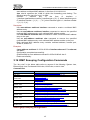
3.16 IGMP Snooping Configuration Commands .............................................. 117
3.17 802.1x Configuration Commands ........................................................... 123
3.18 STP Commands ..................................................................................... 129
3.19 SNMP Configuration Commands ............................................................ 138
3.20 System Log Commands ......................................................................... 144
3.21 ACL Configuration Commands ............................................................... 145
3.22 FRP Commands ..................................................................................... 147
3.23 RMON Commands ................................................................................. 154
3.24 SNTP Commands .................................................................................. 160
3.25 SMTP Commands .................................................................................. 161
3.26 ALARM Commands ................................................................................ 163
3.26.1 E-mail alarm Commands .............................................................. 163
3.26.2 Relay alarm Commands ............................................................... 168
4 Ordering Information ....................................................................................... 173
5 Appendix I Compatible SFP Module................................................................ 174
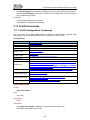
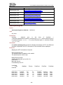
Reversion History
Version
Date
Description
1.00
Sep 9, 2009
Initial release
2.00
Feb 9, 2010
Add new features
2.01
Jun 11, 2010
Update 2.11, add 2.14.3, 2.14.4, 2.14.5
2.02
Oct 22, 2010
1. Add kernel version item at system information page
2. Modify IGMP snooping MISC page
3. Add FRP Ring statistics at statistics tab
3.00
Jun 28, 2011
Add Command Line Interface(CLI)
3.1
Mar 22,2012
Software upgraded
3.2
Dec 3,2012
1.
2.
3.
4.
5.
6.
Added Product Photo
Modified Port Configuration
Modified Power Supply Option
Modified Physical and Environmental Parameters
Modified Ordering Information
Added
Appendix
Compitable
SFP
Module
Information
KY-3120DM Industrial Ethernet Switch User Guide
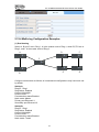
1 Introduction
KY-3120DM Industrial Ethernet Switches are designed to meet various industrial
application needs and provide customer with a high-end industrial Ethernet network
communication solution. KY-3120DM high availability and reliability, as well as the rich
security features make it ideal for data transmission securely. KY-3120DM provides
powerful management capabilities, and can be managed through Web. It is designed
to apply dual power supplies for redundancy with wide DC input range and support
DIN rail and panel mounting for installation in industrial environments.
“Fast Ring Protection” (FRP) is designed specially for industrial applications, providing
fast Ethernet ring protection and recovery within 30ms. From the management
interface, users can choose either port from normal Ethernet port or trunk port to form
an Ethernet ring for faster recovering and wider bandwidth.
1.1 Features
Fast Ring Protection (FRP), Spanning Tree Protocol (STP), Rapid Spanning Tree
Protocol (RSTP) for Ethernet ring protection and quick recovery.
Supports 8K MAC addresses with MAC address auto learning and upgrade
function
Supports 4K VLAN, supports 802.1Q, port based, protocol based VLAN; supports
Generic Attribute Registration Protocol (GARP) and GARP VLAN Registration
Protocol (GVRP) for flexible network planning and management
Dual power input for high reliability
Static and dynamic port aggregation for bandwidth management
Port rate limit, broadcast storm control, port mirroring, rich Quality of Service
(QoS) features for data traffic control and management
Storm control for any combination of multicast, broadcast and DLF traffic
Supports blackhole MAC address filtering, static and dynamic MAC address
management for network security
Supports Access Control List (ACL)
Supports 802.1x, IGMP snooping, SNTP and SMTP
Web management interface and CLI for network management
SNMP V1, V2c, V3; supports RMON statistics, history, alarm and event
On line firmware upgrade
Two privilege level accounts
Syslog
DIN rail or panel mounting for easy installation
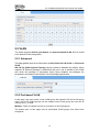
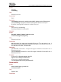
1.2 Product Photo
1
KY-3120DM Industrial Ethernet Switch User Guide
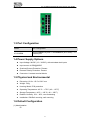
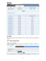
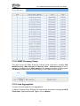
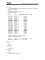
1.3 Port Configuration
Model
Port Configuration
KY-3120DM
16x10/100BaseTX ports + 4x1000BaseX (SFP slots) + 1 x
Console port
1.4 Power Supply Options
Input Voltage: 24VDC (12 ~ 36VDC), with redundant dual inputs
Input current:<0.55A@24VDC
Overload Current Protection: Present
Reverse Polarity Protection: Present
Connector: 6-contact terminal blocks
1.5 Physical and Environmental
Dimension: 60.2 x 115.5 x 138.5 mm
Weight: 760g
Housing: Metal, IP30 protection
Operating Temperature: -40°C ~ +75°C (-40 ~ 167°F)
Storage Temperature: -40°C ~ +85°C (-40 ~ 185°F)
Relative Humidity: 10% ~ 95%, non-condensing
Installation: DIN-Rail mounting, wall mounting
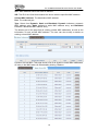
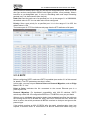
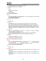
1.6 Default Configuration
(1) Administration
IP:
2
KY-3120DM Industrial Ethernet Switch User Guide
IP Address:
IP Sub network:
IP Gateway:
192.168.0.253
255.255.255.0
192.168.0.201
Accounts:
User Level:
User Name:
Password:
User
manager
123
Administrator
superuser
123
State:
Flow Control:
Learning:
Rate limit:
Negotiation:
enabled
disabled
enabled
disabled
disabled (fiber port)
enabled (copper port)
(2) Port
(3) VLAN
VLAN mode:
Static VLAN:
Port VID:
Port link type:
Frame type:
None
1, including all ports
1
hybrid
admit all
(4) Protocols
Spanning tree: disabled
802.1x:
disabled
LACP:
disabled
GARP/GVRP: disabled
IGMP Snooping: disabled
FRP
disabled
(5) SNMP
Community Name: public
Privilege:
RO
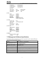
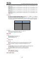
1.7 Management Software Specification
The following table summarizes the protocols supported by the Industrial Ethernet
switch in the current released software.
TCP/IP
ARP, ICMP, IP, TCP and UDP
Web management server
Http Server. Supports goahead-2.1.8.Java scripts,
Java Applet and CGI
Spanning Tree Protocol
IEEE 802.1d/1w
Four-level priority queuing
IEEE 802.1p
Port-based VLAN
SVL
Tag-based VLAN
IEEE 802.1q (IVL and SVL), GVRP
Protocol-based VLAN
IEEE 802.1v
Trunking
IEEE 802.3ad, LACP
3
KY-3120DM Industrial Ethernet Switch User Guide
Authentication
IEEE 802.1x
RMON
RFC1757
SMTP
RFC2821
SNTP
RFC2030
IGMP Snooping
RFC2236
4
KY-3120DM Industrial Ethernet Switch User Guide
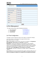
2 Web Management Function
The switch can be managed and monitored via a Web browser. The default login user
name and password are given in Section 1.5 of this manual. Go to
http://192.168.0.253 , type user name and password as shown in Section 1.5 to log in
to the switch.
2.1 Conventions
Convention
Boldface
italic
<>
Description
Keywords are in Boldface.
Tab page names are in italic.
Button names are in <>.
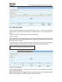
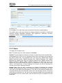
2.2 System Information
After login, the System Information page is shown, displaying the basic information of
the switch as below.
2.3 Advanced Configuration
This page is to configure the following functions and protocols globally enabled or
disabled:
IGMP Snooping
IGMP Flood
GVRP
STP
LACP
IEEE 802.1x
FRP
5
KY-3120DM Industrial Ethernet Switch User Guide
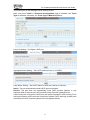
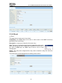
2.4 Port Management
This page configures port related management functions:
1.
2.
3.
4.
Port Configuration
Port Aggregation
Port Bandwidth
Port Mirroring
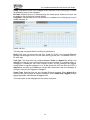
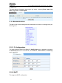
2.4.1 Port Configuration
This page is used to configure the ports. Click <Apply> to activate the settings.
A list of port status is at the bottom of the page as shown follows.
Port: Specify the port to configure.
State: Enable/disable the state funtion. Only when it is enabled, can Negotiation,
Speed&Duplex, Flow Control and Learning be configured.
Negotiation: There are two selectyions: Force and Auto. “Auto” provides a
mechanism for exchanging configuration information between two ends of a link
segment, and automatically selecting the highest performance mode of operation
supported by both devices if it is enabled, and “Force” makes the possibility to
manually configure Speed&Duplex, Flow Control and Learning.
Speed&Duplex: There are four selsctions: 10M Half, 10M Full, 100M Half and
100MFull.
Flow Control: Flow control can eliminate frame loss by “blocking” traffic from end
station or segment connected directly to KY-3120DM. The parameter allows flow
control to be enabled or disabled. If it is disabled, the port operates at full speed.
6
KY-3120DM Industrial Ethernet Switch User Guide
Learning: Enbale/disable port MAC learning function.
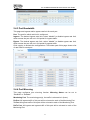
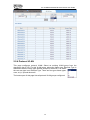
2.4.2 Port Aggregation
KY-3120DM supports up to 13 link aggregation groups, and each group can have up
to 8 ports.
This page sets link aggregation. There are two types of aggregation: manual and
static.
Manual aggregation: A manual trunk can only be manually set or deleted; any port in
a manual trunk shall have this port’s Link Aggregation Control Protocol (LACP)
disabled, while the global LACP can be either enabled or disabled.
Static LACP aggregation: A static LACP trunk can only be manually set or deleted;
any port in a static LACP trunk shall have this port’s Link LACP enabled. When a static
LACP trunk is (manually) deleted, all ports of this trunk with “up” status will generate
one or more dynamic LACP trunk(s) automatically.
A trunk may be configured as a mirror port, but it is not allowed to configure a trunk as
a monitoring port.
There are four tabs on this page to configure various parameters:
(1)Aggregate Groups – Create and configure a trunk.
The switch can have up to 13 trunks.
Trunk ID: 13 trunk IDs in the drop-down list of (from T1 to T13).
Trunk Name: To give a name for the selected trunk.
Trunk Type: This drop-down list includes manual trunk and static LACP trunk.
Port: To choose up to 8 ports to form the trunk.
7
KY-3120DM Industrial Ethernet Switch User Guide
The bottom part of this tab page lists all existing trunks.
Note: Only when LACP in Advanced Configuration page is enabled, can Trunk
Type be selected; otherwise, the Trunk Type is Manual bydefault.
Lacp Port Setting – Configure LACP port
Aggregate Based Setting – Set LACP system priority (1 to 65535).
Lacp Status Setting – Set LACP status for each port (Active or Passive).
Active: The port automatically sends LACP protocol packets.
Passive: The port does not automatically send LACP protocol packets. It only
responds when it receives an LACP protocol packet from the opposite device.
A link having one or two active LACP ports can perform dynamic LACP trunking. A link
having two passive LACP ports will not perform dynamic LACP trunking, as both ports
are waiting for LACP protocol packets from the opposite device.
8
KY-3120DM Industrial Ethernet Switch User Guide
2.4.3 Port Bandwidth
This page sets ingress and/or egress rate limit for each port.
Port: The port for which rate limit is configured.
Ingress: The desired ingress rate limit, select “disable” to disable ingress rate limit,
which means the port will run in full speed for ingress traffic.
Egress: The desired egress rate limit, select “disable” to disable egress rate limit,
which means the port will run in full speed for egress traffic.
Click <apply> to activate the configurations. The bottom part of this page shows a list
of rate limits for each port.
2.4.4 Port Mirroring
This page configures port mirroring function. Mirroring Status can be set to
“Disabled” or “Enabled”.
Monitoring Port: The monitoring port(s), the traffic is mirrored to it (them).
Rx Port: All ingress traffic of this port will be mirrored to each of the Monitoring Port.
Tx Port: All egress traffic of this port will be mirrored to each of the Monitoring Port.
Rx/Tx Port: All ingress and egress traffic of this port will be mirrored to each of the
Monitoring Port
9
KY-3120DM Industrial Ethernet Switch User Guide
2.5 VLAN
The switch supports 802.1Q, port-based, and protocol-based VLAN. 802.1Q VLAN
is the default VLAN configuration.
2.5.1 Advanced
This page globally sets the VLAN mode to be NO VLAN, 802.1Q VLAN, or Port-based
VLAN.
802.1Q Tag VLAN Ingress Filtering may be enabled or disabled (by default). When
enabled, an Ethernet package is discarded if this port is not a member of the VLAN
with which this package is associated. When being disabled, all packages are
forwarded in accordance with the 802.1Q VLAN bridge specification.
2.5.2 Port-based VLAN
In this page, user can create a new VLAN group with specific VID and VLAN group
name. Up to 256 VLAN groups can be created; each VLAN group can have an ID
number from 1 to 4094.
Member: Check to indicate the port is a member of the VLAN group.
The bottom part of this page lists all port-based VLAN groups that have been
configured.
10
KY-3120DM Industrial Ethernet Switch User Guide
2.5.3 802.1Q VLAN
There is a default VLAN group with VLAN identifier (VID) of 1, each port is a member
of this group by default, and remains as a member before it is removed from the
group.
There are three tabs on this page for VLAN configuration.
(1)802.1Q VLAN
On this tab page, the user can create a new VLAN group with specific VID and VLAN
group name. Up to 256 VLAN groups can be created; each VLAN group can have an
ID number from 1 to 4094.
The bottom part of this page lists all existing VLAN groups, as well as the information
of each VLAN group. Users can also modify or delete an existing VLAN group.
Note: It is not allowed to delete VLAN group 1.
(2) 802.1Q Configuration
This tab page configures a VLAN group; each port can be configured as a specific
state for this VLAN group:
Tag: Indicates the port is a tagged member of the VLAN group. All packets forwarded
by the port are tagged. The packets contain VLAN information.
11
KY-3120DM Industrial Ethernet Switch User Guide
Untag: Indicates the port is an untagged VLAN member of the VLAN group. Packets
forwarded by the port are untagged.
Exclude: Indicates the port is excluded from the VLAN group. However, the port can
be added to the VLAN group through GARP.
Forbidden: Indicates the port is not allowed to be added to the VLAN group, even if
GARP indicates so.
(3)802.1Q Port
This tab page configures 802.1Q VLAN port parameters:
PVID: Each port can have only one Port VLAN ID (PVID), an untagged Ethernet
package will be tagged a VID of PVID when arriving at the port. The default PVID is 1
for each port.
Link Type: The drop-down list contains Access, Trunk and Hybrid (by default). An
Access port has only one VLAN and the tag is removed when it is sending data (i.e.
Untagged); a Trunk port can have multiple VLANs, and all packages are tagged,
except when an egress package is in a VLAN group with VID the same as PVID; a
Hybrid port is similar as a Trunk port, except that it leaves the user more flexibility to
configure each port as Tagged or Untagged.
Frame Type: Specifies how the port accepts Ethernet package. When Admit All is
selected, the port accepts all ingress packages; while Admit Only Tagged accepts
tagged packages, and discards untagged ones.
The bottom part of this tab page lists the status of all ports.
12
KY-3120DM Industrial Ethernet Switch User Guide
2.5.4 Protocol VLAN
This page configures protocol VLAN. Select an existing VLAN group from the
drop-down list of VID. For this VLAN group, select the frame type. Ethernet Type is
associated with the frame type slected, except for Ethernet II, for which
the user can type in an Ethernet Type. There are five types frame types:
none, at, ip, ipx and ethernetii.
The bottom part of this page lists all protocol VLAN groups configured.
13
KY-3120DM Industrial Ethernet Switch User Guide
2.5.5 GARP
GARP VLAN Registration Protocol (GVRP) is based on Generic Attribute Registration
Protocol (GARP). They are standard protocols described in IEEE 802.1D.
Before configuring GARP, make sure GVRP is enabled (see Section 2.3 of this
manual for details). There are two tab pages:
GARP: This tab page sets GARP Join Time, Leave Time, and Leaveall Time.
Leaveall Time must be greater than Leave Time, and Leave Time must be twice
greater than Join Time.
GVRP: This tab page sets the GVRP parameters for each port. For a selected Port, if
GVRP is enabled, the Registration Type can be set to Normal (default), Fixed, or
Forbidden. Normal registration allows dynamic passing, registration, and
de-registration of both dynamic and static VLANs; Fixed registration allows passing
static VLANs, as well as manual registration and de-registration of VLANs; while
Forbidden prohibits the port from passing, registration or de-registration of VLANs.
The bottom part of GVRP tab page lists the GVRP attribute of all ports.
14
KY-3120DM Industrial Ethernet Switch User Guide
2.6 QoS
This managed switch supports Quality of Service (QoS). QoS priority is disabled by
default.
2.6.1 QoS Configuration
There are two tab pages:
General: This page globally sets priority to be “Disabled” or “Enabled”. By default, the
priority is disabled.
Port QoS Configuration: This tab page sets QoS parameters for each port. For a
15
KY-3120DM Industrial Ethernet Switch User Guide
selected Por, if 802.1p and DSCP is set to be enabled, the Port-based Priority can
be set to 0 to 7.
2.6.2 Scheduling Mechanism
This page sets the queue scheduling algorithm and the related parameters.
Scheduling Mechanism includes Strict Priority and Weighted Round-Robin
(WRR).
Strict Priority: To use the strict priority (SP) algorithm for queue scheduling. Packets
in a higher priority queue are processed before those in the lower priority queues.
Weighted Round-Robin (WRR): To use the weighted round robin (WRR) algorithm
for queue scheduling.
WRR Queue Priority Weight: To specify the weights to be assigned to queues 1
through 4.The value ranges from 1 to 55.
2.6.3 Transmit Queues
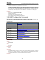
This page sets the 802.1p priority to local precedence mapping. The following table
lists default 802.1p priority to local precedence mapping:
16
KY-3120DM Industrial Ethernet Switch User Guide
802.1p priority
Local precedence
0
1
2
3
4
5
6
7
Q1
Q1
Q2
Q2
Q3
Q3
Q4
Q4
2.6.4 DSCP Map
This page sets the DSCP value for each of the 802.1p priorities.
2.7 Forwarding
2.7.1 Unicast MAC Address
There are two tab pages: MAC Address Configuration and Dynamic Unicast MAC.
MAC Address Configuration: On this page, an entry can be added or modified in MAC
17
KY-3120DM Industrial Ethernet Switch User Guide
table. MAC address entries can also be deleted.
VID: The ID of the VLAN that contains the device with the specified MAC address.
Unicast MAC Address: The destination MAC address.
Port: The outbound port.
Type: Select from Dynamic, Static and Blackhole. Dynamic indicates a dynamic
MAC address entry; Static indicates a static MAC address entry; and Blackhole
indicates a blackhole MAC address entry.
The bottom part of the page lists all existing unicast MAC addresses, as well as the
information of each unicast MAC address. The user can also modify or delete an
existing unicast MAC address.
Dynamic Unicast MAC: This page shows a list of all dynamic unicast MAC addresses.
An entry in the MAC table can be deletedby clicking <Delete>.
18
KY-3120DM Industrial Ethernet Switch User Guide
2.7.2 Multicast MAC Address
This page sets a multicast MAC address entry, and each multicast MAC address entry
contains VLAN ID, multicast address and forward ports.
VID: The VLAN that contains the forwarding ports.
Multicast MAC Address: Multicast MAC address, in the form of H-H-H-H-H-H.
Member: The forwarding ports for the specified multicast MAC group address. One or
more individual ports can be defined.
The bottom part of this page lists all existing multicast MAC addresses, as well as the
information of each multicast MAC address. The user can also modify or delete an
existing multicast MAC address.
2.7.3 IGMP Snooping
There are three tab pages on this webpage for a user to configure various
parameters:
(1) IGMP Snooping
On this page, a user can enable IGMP Snooping feature of each VLAN. By default,
the IGMP Snooping feature is disabled.
The bottom part of this page lists all VLAN IGMP Snooping feature status.
19
KY-3120DM Industrial Ethernet Switch User Guide
(1) Route Port
On this page, the user can configure a port in the specified VLAN as a static router
port. By default, a port is not a static router port.
The bottom part of this page lists static router ports of all VLANs.
(3)Misc
This tab page configures IGMP Snooping Misc configuration parameters: Host
Timeout, Route Timeout, IGMP Querier, Query Transmit Interval, Max Response Time,
and Last Member Query Interval.
Host Timeout: It is in the range of 200 to 1000; by default, the value is 260 seconds.
Route Timeout: It is in the range of 1 to 1000; by default, the value is 105 seconds.
IGMP Querier: Enable/disable IGMP Querier function.
Query Transmit Interval: It is in the range of 1 to 255; by default, the value is 125
seconds.
Max Response Time: It is in the range of 1 to 25; by default, the value is 10 seconds.
Fast Leave: Enbale/disable Fast Leave function.
20
KY-3120DM Industrial Ethernet Switch User Guide
2.8 Security
2.8.1 Management Security
This page sconfigures 802.1x system configuration: Authentication RADIUS Server IP,
Authentication Port, Authentication Shared Key, Accounting RADIUS Server IP,
Accounting Port and Accounting Shared Key.
Authentication RADIUS Server IP: IP address of the radius server to be used, a
valid unicast address in dotted decimal notation; the default value is 192.168.0.234.
Authentication Port: UDP port number of the radius server, ranging from 1 to 65535,
the default value is 1812.
Authentication Shared Key: The authentication shared key offered by NSP.
Accounting RADIUS Server IP: The IP address of the accounting RADIUS Server.
Accounting Port: UDP port number of the radius server, ranging from 1 to 65535, the
default value is 1813.
Accounting Shared Key: a shared key for radius messages, a string of 1 to 15
characters.
21
KY-3120DM Industrial Ethernet Switch User Guide
2.8.2 Port Authentication
There are two tabs on this page for the user to configure various parameters of
802.1x.
(1)802.1x Port
On this tab page, 802.1x Admin, Re-authentication as well as Guest VLAN can be
enabled for a specified Ethernet port, and a specific PortControl mode can also be
selected. The PortControl can be selected among Auto, ForceAuthorized and
ForceUnauthorized.
Auto: The auto access control mode. When a port operates in this mode, all the
unauthenticated hosts connected to it are unauthorized, and only EAPoL packets can
be exchanged between the switch and the hosts. And the authenticated hosts
connected to the port are authorized to access the network resources.
ForceAuthorized: The force-authorized access control mode. When a port operates
in this mode, all the hosts connected to it can access the network resources without
authentication.
ForceUnauthorized: The force-unauthorized access control mode. When a port
operates in this mode, the hosts connected to it cannot access the network resources.
The bottom part of this page lists all 802.1x port status.
22
KY-3120DM Industrial Ethernet Switch User Guide
(2)802.1x Misc
This tab page configures 802.1x configurations such as Quiet Period, Tx Period,
Supplicant Timeout, Server Timeout, Max Request Count, Reauth Period and Guest
VLAN.
Quiet Period: This timer sets the quiet-period. When a supplicant system fails to pass
the authentication, the switch quiets for the set period before it processes another
authentication request re-initiated by the supplicant system. During this quiet period,
the switch does not perform any 802.1x authentication-related actions for the
supplicant system. The value is in the range of 1 to 65535, and the default setting is
60 seconds.
Tx Period: Sets the transmission timer. This timer sets the tx-period and is triggered
in two cases. One is when the client requests authentication, the switch sends a
unicast request/identity packet to a supplicant system and then triggers the
transmission timer. The switch sends another request/identity packet to the supplicant
system if it does not receive the reply packet from the supplicant system when this
timer times out. The other is that when the switch authenticates the 802.1x client that
cannot request authentication actively, the switch sends multicast request/identity
packets periodically through the port with 802.1x function enabled, in this case, this
timer sets the interval to send the multicast request/identity packets. It is in the range
of 1 to 65535, the default setting is 30 seconds.
Supplicant Timeout: This timer sets the supp-timeout period and is triggered by the
switch after the switch sends a request/challenge packet to a supplicant system. The
switch sends another request/challenge packet to the supplicant system if the switch
23
KY-3120DM Industrial Ethernet Switch User Guide
does not receive response from the supplicant system when this timer times out. It is
in the range of 1 to 300, the default setting is 30 seconds.
Server Timeout: This timer sets the server-timeout period. After sending an
authentication request packet to the radius server, a switch sends another
authentication request packet if it does not receive response from the radius server
when this timer times out. It is in the range of 1 to 300, the default setting is 30
seconds.
Max Request Count: Sets the maximum number of times that a switch sends
authentication request packets to a user. It is in the range of 1 to 10, and the default
setting is 2.
Reauth Period: Sets re-authentication interval in seconds. After this timer expires, the
switch reminds 802.1x re-authentication. It is in the range of 60 to 7200, and the
default setting is 3600 seconds.
Guest VLAN: Select a guest VLAN to provide limited services to clients.
2.8.3 Storm Control
This page sets the thresholds of the specified traffic type.
The traffic type can be chosen from None,
Broadcast, Multicast, Destination Lookup Failed
(DLF),
Broadcast+Multicast,
Broadcast+DLF,
Multicast+DLF, and Broadcast+Multicast+DLF.
The Rate is in the range of 64 to 1000000.
By default, the traffic type is “None”.
24
KY-3120DM Industrial Ethernet Switch User Guide
2.9 ACL
ACL (Access Control List) is used to achieve the packet filtering function by the
configuration of matching rules and processing operation(s). An ACL is a sequential
collection of permit and deny conditions that apply to packets. When a packet is
received on a port, the switch compares the fields in the packet with any applied ACLs
to verify that the packet has the required permissions to be forwarded, based on the
criteria specified in the access lists.
There are three following types of ACL:
Basic IP ACL: Packets filtering only based on source IP address.
Advance IP ACL: Packets filtering based on source IP address, destination IP
address and some IP protocol types mentioned following.
L2 ACL: Packets filtering based on source MAC address, destination MAC addresses,
802.1p priority and L2 protocol type.
2.9.1 Management ACL
In order to flexibly configure ACL rule, the ACL ID is divided into three segments: 1-20
for Basic IP ACL, 21-40 for Advanced IP ACL and 41-60 for L2 ACL. ACL Rule page
sets different ACL rules based on the range of ACL ID.
The bottom part of this page lists all configured ACL IDs. Parameter Rules shows the
number of rules that has already been configured for this ACL ID.
25
KY-3120DM Industrial Ethernet Switch User Guide
2.9.2 ACL Rule
(1) Basic IP ACL
This page configures Basic IP ACL rules. Up to 10 rules per ACL ID can be set; each
rule ID can only be used once. All parameters, including Rule ACL ID, Source IP and
IP Mask must be set, and the Action can be set to Permit or Deny.
Permit: Permit the access of IP matched with rule.
Deny: Deny the access of IP matched with rule.
The bottom part of this page lists all configured Basic IP ACL rules.
(2) Advanced IP ACL
This page configures ACL rules based on packet Src IP Address, Dst IP Address, IP
26
KY-3120DM Industrial Ethernet Switch User Guide
Protocol type and other protocol features, such as TCP or UDP source port,
destination port and ICMP protocol message types etc.
Rule ID: Identification of the ACL rule, its value is in the range of 1 to 10.
Protocol Type: An existing protocol type such as Icmp, Igmp, Tcp, Udp, Ospf or an
interger between 1 and 255.
Src IP Address: Source host IP address.
Src IP Mask: Source host IP subnet mask.
Src L4 Port: TCP/UDP source port. Echo, Ftp, Telnet, Smtp
, Www only for protocol type TCP; Dns, Echo, Ntp, tftp, Snmp, Snmptrap and Syslog
only for protocol Udp, or an integer from 1 to 65535.
Note: IETF IANA defines three groups of ports: Well Known Ports (0-1023),
Registered Ports (1024-49151) and Dynamic and/or Private Ports (49152-65535).
Dst IP Address: Destination host IP address, in the range of 1 to 10.
Dst IP Mask: Destination host IP subnet mask.
Dst L4 Port: TCP/UDP destination port, Echo, Ftp, Telnet, Smtp, Www only for
protocol type TCP ; Dns, Echo, Ntp, tftp, Snmp, Snmptrap and Syslog only for protocol
Udp, or an integer from 1 to 65535.
Action: Permit or deny access of the package matched with rules.
The bottom part of this page lists all configured Advanced IP ACL rules.
(3) L2 ACL
This page configures Src MAC Address, Src MAC Address Mask, Dst Mac Address,
Dst MAC address Mask, and Action that can be selected as Permit or Deny.
Rule ID: Identification the ACL rule, in the range of 1 to 10.
Src MAC Address: Source host MAC address.
27
KY-3120DM Industrial Ethernet Switch User Guide
Src MAC Address Mask: Source host MAC address mask.
Dst MAC Address: Destination host MAC address.
Dst MAC address Mask: Destination host MAC address mask.
Action: Permit or deny the access for the package matched with rules.
The bottom part of this page lists all configured L2 ACL rules.
2.9.3 Port Binding
This page configures the binding of an Ethernet port to a specified ACL ID. If a port is
bound, it will take effect on all the rules associated to this ACL ID.
The bottom part of this page lists all ACL binding Ports.
28
KY-3120DM Industrial Ethernet Switch User Guide
2.10 Statistics
Statistics inlucdes Port Status, Port Statistics, VLAN List, MAC Address Table, Link
Aggregation and FRP Ring Status.
2.10.1 Port Information
This page shows the State, Link, Negotiation, Speed&Duplex, Flow Control, and
Learning of each Ethernet port.
29
KY-3120DM Industrial Ethernet Switch User Guide
This page shows the Port, Type,Link, SFP Vendor and Wavelength&Distance.
SFP DDM Alarm :Enable or disable to trigger an e-mail alarm when over temperature
or out the range of TX/RX power.
2.10.2 Port Statistics
This page shows the TxGoodPkts, TxBadPkts, RxGoodPkts, RxBadPkts, TxAbort,
Collision and DropPkt of each Ethernet port.
TxGoodPkts: The total number of outgoing normal packets on the port, including
outgoing normal packets and normal pause frames.
TxBadPkts: The total number of outgoing error frames.
RxGoodPkts: The total number of incoming normal packets on the port, including
incoming normal packets and normal pause frames.
RxBadPkts: The total number of incoming error frames.
TxAbort: The number of transmission failures due to various reasons, such as
collisions.
Collision: The number of detected collisions.
DropPkt: The number of packets dropped for various reasons.
30
KY-3120DM Industrial Ethernet Switch User Guide
2.10.3 VLAN List
This page shows all VLAN lists, including VID, Name, Type, Tagged, Untagged and
Forbidden. Type is either Static or Dynamic. Tagged includes all ports out of which
packets are sent tagged; Untagged includes all ports out of which packets are sent
untagged; and Forbidden includes all ports that can not be added to the VLAN group.
2.10.4 MAC Address Table
This page shows information about unicast MAC Address in the Unicast MAC address
table, including VID, Unicast MAC Address, Port, and Type. Type is Dynamic,
Static, Blackhole or Learned.
31
KY-3120DM Industrial Ethernet Switch User Guide
2.10.5 IGMP Snooping Group
This page shows the IGMP Snooping multicast group information, including VID,
Multicast Group, MAC Address and Member Ports. Multicast Group is the IP
address of a multicast group, MAC Address is the address of a MAC multicast group,
and Member Ports include all ports belonging to this IGMP Snooping group.
2.10.6 Link Aggregation
There are three tab pages for Link Aggragation:
(1) Manual Trunking Group: Displays the manual trunk information, including Trunk ID,
Trunk Name, Type and Port List. Type is fixed to Manual.
32
KY-3120DM Industrial Ethernet Switch User Guide
(2) Static Trunking Group: Displays the static trunk information, including Trunk ID,
Trunk Name, Type and Port List. Type is fixed to Static.
(3) LACP Trunking Group: Displays the LACP trunk information, including Priority,
MAC of Actor and Partner. It also shows the Key, priority and Active state of
member ports.
2.10.7 FRP Ring status
This page shows the FRP Ring status information, including Ring ID, Ring Status,
Ring Node, Link Status, Primary Port Status, Secondary Port Status, Coupling Node,
Coupling Link Status, Control Port Status and Backup Port Status.
Ring ID: Shows the ring ID to identify which ring this switch belongs to In FRP
protocol.
Ring Status: Shows the status of the FRP ring.
Ring Node: Shows the type of the ring node on a FRP ring. There are two types of
node: Master and Transit.
Link Status: Shows the link status of the ring.
Primary port Status: Shows the status of Primary port.
Secondary port Status: Shows the status of Secondary port.
Coupling Node: Shows the switch port coupling mode, including four types of nodes:
Dual homing, Coupling Primary, Coupling Backup and Peer Coupling.
Coupling Link Status: Shows the ring status of switch coupling link mode.
Control Port Status: Shows the status of the port connected to the other ring as the
primary connect between rings.
Backup Port Status: Shows the status of the port that is connected to the other ring
as backup.
33
KY-3120DM Industrial Ethernet Switch User Guide
2.11 Spanning Tree
Spanning Tree Protocol (STP) is a standard protocol described in IEEE 802.1D. And
Rapid Spanning Tree Protocol (RSTP, IEEE 802.1w) is an evolution of the 802.1D.
2.11.1 STP
Before configuring STP, make sure STP is enabled (see section 2.3 of this manual for
details). There are three tab pages:
(1) Basic STP
This page sets bridge configurations: Priority, Hello Time, Max Age, Forward Delay
Time and Fast Detection.
Priority: Sets the priority of the switch, it is in the range of 0 to 65535, the default
value is 32768.
Hello Time: Sets the hello time of the switch, it is in the range of 1 to 10 seconds, the
default value is 2 seconds.
A root bridge regularly sends out configuration BPDUs to maintain the stability of the
existing spanning tree. If the switch does not receive a BPDU packet in a specified
period, the spanning tree will be recalculated because BPDU packet times out. When
a switch becomes a root bridge, it regularly sends BPDUs at the interval specified by
the hello time configured. The other none-root-bridge switches adopt the interval
specified by the hello time.
Max Age: Sets the max age of the switch, it is in the range of 6 to 40 seconds, the
default value is 20 seconds.
STP is capable of detecting link failures and automatically restoring redundant links to
the forwarding state. In CIST, switches use max age parameter to judge whether a
received configuration BPDU times out. Spanning trees will be recalculated if a
configuration BPDU received by a port times out.
Forward Delay Time: Sets the forward delay of the switch, it is in the range of 4 to 30
seconds, and the default value is 15 seconds.
Fast Detection: To enable/disable the fast detection function. It is disabled by default.
To prevent the occurrence of a temporary loop, when a port changes its state from
discarding to forwarding, it undergoes an intermediate state and waits for a specific
period to synchronize with the state transition of the remote switches. This state
transition period is determined by the forward delay configured on the root bridge. The
forward delay setting configured on a root bridge applies to all non-root bridges.
As for the configuration of the three time-related parameters (namely, the hello time,
forward delay and max age parameters), the following formulas must be met to
prevent frequent network jitter:
34
KY-3120DM Industrial Ethernet Switch User Guide
2 × (forward delay – 1 second) >= max age
max age >= 2 × (hello time + 1 second)
(2) STP info
This page shows the basic information of Designated Bridge, including Bridge ID,
Root Bridge ID, Root Port and Root Path Cost.
Bridge ID: ID of this switch bridge.
Root Bridge ID: ID of the root bridge.
Root Path Cost: Cost of the path from the switch to the root bridge.
(3) STP Port Attributes
On this page, the user can enable STP, Port Fast, Root protection for each port,
and also can set Path Cost and Priority.
Port Fast: In order to allow the port to transite to forwarding state auickly, enable the
STP Port Fast feature, which can immediately transits the port into STP forwarding
state upon linkup. This port still participates in STP. In case that the port forms a loop,
it will transit into STP blocking state.
Root protection: By default, the root protection function is disabled.
Due to configuration error or malicious attack, the root bridge in a network may
receive configuration BPDUs with priorities higher than that of a root bridge, which
causes new root bridge to be elected and network topology jitter. In this case, data
flows that should have been transmitted along a high-speed link are led to a
low-speed link. This problem can be resolved by enabling root protection function.
35
KY-3120DM Industrial Ethernet Switch User Guide
Root-protection-enabled ports can only be kept as designated ports. When a port of
this type receives configuration BPDUs with higher priorities, more precisely, when it
becomes a non-designated port, it turns to discarding state and stops forwarding
packets (as if it is disconnected from the link).
Path Cost: Sets the path cost of a specified por. It is in the range of 1 to 200000000,
the default value is 55. You can also make it auto-configured.
Priority: Sets a port priority for a specified port. It is in the range of 0 to 255, the
default value is 128.
The bottom part of STP Port Attributes tab page lists the STP attributes of all ports.
2.11.2 RSTP
Before configuring RSTP, make sure RSTP is enabled (see section 2.2 of this manual
for details). The STP parameters are also in effect.
In this page, you can set port Point to Point and Protocol Migration, and set Edge
Port to “No” or “Yes”.
Point to Point: Indicates the link connected to the current Ethernet port is a
point-to-point link.
Protocol Migration: For backward compatibility with 802.1D switches, RSTP
selectively sends 802.1D configuration BPDUs or TCN BPDUs on a per-port basis.
When a port is initialized, the migration-delay timer is started (specifies the minimum
time during which RSTP BPDUs are sent), and RSTP BPDUs are sent. While this
timer is active, the switch processes all BPDUs received on that port and ignores the
protocol type.
If the switch receives an 802.1D BPDU after the port's migration-delay timer has
expired, it assumes that it is connected to an 802.1D switch and starts using only
36
KY-3120DM Industrial Ethernet Switch User Guide
802.1D BPDUs. However, if the RSTP switch is using 802.1D BPDUs on a port and
receives an RSTP BPDU after the timer has expired, it restarts the timer and starts
using RSTP BPDUs on that port.
Edge Port: Select “Yes” to configure the specified Ethernet port as edge port. By
default, all Ethernet ports of a switch are non-edge ports.
An edge port is a port that is directly connected to a user terminal instead of another
switch or a network segment. Rapid transition to the forwarding state is applied to
edge ports, because no loop can be incurred by network topology change on those
ports. Setting a port to be an edge port can make it to turn into forwarding state rapidly.
And it is advised to configure an Ethernet port directly connected to a user terminal as
an edge port.
Normally, configuration BPDUs cannot reach an edge port because the port is not
connected to another switch. But when the BPDU guard function is disabled on an
edge port, configuration BPDUs sent deliberately by a malicious user may reach the
port. It changes itself to a non-edge port if an edge port receives a BPDU.
The bottom part of Basic RSTP tab page lists the RSTP attributes of all ports.
2.12 FRP configuration
Before configuring FRP, make sure FRP is enabled (see section 2.3 Advanced
37
KY-3120DM Industrial Ethernet Switch User Guide
Configuration of this manual for details).
In FRP protocol, up to 2 levels of rings are allowed; each level has a Ring ID. A switch
can be a node of a ring.
2.12.1 FRP Ring
This page sets FRP ring configuration: Ring ID, Ring Status, Control VLAN, Protect
VLAN, Fast detection status, Node mode, Primary port and Secondary port.
Ring ID: The ring ID identifies which ring this switch belongs to. In FRP protocol, there
are two levels of rings: Ring 1 and Ring 2.
Ring Status: To enable/disable the ring for the specified switch. Note that a switch
can only be enabled in one ring.
Control VLAN: This is the VLAN used for transferring FRP protocol packets within the
FRP ring.
Protect VLAN: It is used for transferring data packets. When a VLAN is created in a
ring, this VLAN must be configured as a Protect VLAN or Control VLAN.
Fast detection status: When enabled, the FRP will use the FastHelloTime and
FastFailTime instead of HelloTime and FailTime to send packets periodically to
detect ring connect status.
Node mode: Each switch on a FRP ring is called a node. There are two types of
nodes: Master and Transit. The master node sends HELLO (healthy detect) packet
periodically from its primary port. This packet is transmitted on the ring by the transit
nodes in turn. If the secondary port of the master receives the HELLO packet sent by
itself, this indicates the ring is completed. Otherwise, the HELLO packet cannot reach
itself, and the master node will consider a link failure has occurred in the ring.
The transit nodes are responsible for monitoring the states of the FRP links they are
directly connected to, and notify the master node of the link changes.
Note: A ring should have, and can only have one Master node.
Primary port: The master node sends FRP packets via its primary port.
Secondary port: The master node uses it to receive FRP packets. Block it to prevent
flooding, while unblock it when a link failure has occurred.
The primary and secondary ports of a transit node have the same functions.
The bottom part of this page lists the configuration of each of the two rings.
38
KY-3120DM Industrial Ethernet Switch User Guide
2.12.2 FRP Coupling
This page sets FRP coupling configuration: Ring, Coupling Status, Coupling Mode,
Coupling Control Port and Coupling Backup Port.
Ring: The ring ID associated with coupling functions.
Coupling Status: To enable/disable the coupling function of the selected ring. To
enable this function, the associated ring must be enabled first.
Coupling Mode: There are four coupling modes: Dual homing,
Coupling Primary, Coupling Backup, and Peer Coupling.
Coupling Control Port and Coupling Backup Port play different
roles in different modes. There is a coupling control port and a
coupling backup port in Dual homing mode; there is only a
coupling control port In Coupling Primary and Peer Coupling modes; there is only a
coupling backup port in Coupling Backup mode.
Coupling Control Port: Assign the port that is connected to the other ring as primary
connection between rings. The status of this port is generally set to forwarding.
Coupling Backup Port: Assign the port that is connected to the other ring for backup.
In case that the Coupling Control Port is broken, this port is unblocked.
Coupling Mode configuration rules:
1. Two directly connected rings cannot have the same Ring ID.
2. Within a ring, only one switch can be set as Coupling Primary, and the other one
as Coupling Backup.
3. Within the same level ring, more than one switch can be set as Dual homing.
The bottom part of this page lists the configuration of two coupling rings.
39
KY-3120DM Industrial Ethernet Switch User Guide
2.12.3 FRP Timer
This page sets FRP timer configurations: HelloTime, FailTime, FastHelloTme and
FastFailTime.
HelloTime: Sets hello time of the switch. It is in the range of 1 to 10 seconds. The
default value is 1 second.
FailTime: Sets fail time of the switch. It is in the range of 3 to 30 seconds, and the
default value is 3 seconds.
FastHelloTime: Sets fast hello time of the switch. It is in the range of 10 to 500
millsecondes, and the default value is 10 milliseconds.
FastFailTime: Sets fast fail time of the switch. It is in the range of 30 to 1500
milliseconds. The default value is 30 milliseconds.
These timer values are used in master node. When the hello timer times out, the
master node will send out a hello packet. If the fail timer times out, it indicates that a
link failure has occurred in the ring.
If Fast detection status in FRP Ring tab page is enabled, the master node will use
the FastHelloTime and FastFailTime instead of HelloTime and FailTime to set the
hello timer and fail timer.
To set those parameters, the following rules shall be met:
3* HelloTime < =FailTime and 3* FastHelloTime <= FastFailTime.
40
KY-3120DM Industrial Ethernet Switch User Guide
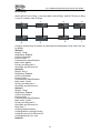
2.12.4 Multi-ring Configuration Examples
(1) Dual homing
Switch A, B and C are in Ring 1, A is the master node of Ring 1; while D,E,F,G are in
Ring 2, and F is the master node of Ring 2.
D
A
F
C
E
B
G
Configure each switch as follows; all unmentioned configurations may have been set
by default.
Switch A:
Ring ID : Ring 1
Ring Status: Enabled
Control VLAN:4091
Protect VLAN: 1
Fast detection status:Enabled
Node mode: Master
Primary port:Ethernet1/1
Secondary port Ethernet1/2
Switch B:
Ring ID : Ring 1
Ring Status: Enabled
Control VLAN:4091
Protect VLAN: 1
Fast detection status:Enabled
Node mode: Transit
41
KY-3120DM Industrial Ethernet Switch User Guide
Primary port:Ethernet1/1
Secondary port Ethernet1/2
Switch C:
Ring ID : Ring 1
Ring Status: Enabled
Control VLAN:4091
Protect VLAN: 1
Fast detection status:Enabled
Node mode: Transit
Primary port:Ethernet1/1
Secondary port Ethernet1/2
Ring: Ring 1
Coupling Status:Enabled
Coupling Mode: Dual homing
Coupling Control Port: Ethernet1/3
Coupling Backup Port: Ethernet1/4
Switch D,E:
Ring ID : Ring 2
Ring Status: Enabled
Control VLAN:4092
Protect VLAN: 1
Fast detection status:Enabled
Node mode: Transit
Primary port:Ethernet1/1
Secondary port Ethernet1/2
Ring: Ring 2
Coupling Status:Enabled
Coupling Mode: Peer Coupling
Coupling Control Port: Ethernet1/3
Coupling Backup Port: none
Switch F:
Ring ID : Ring 2
Ring Status: Enabled
Control VLAN:4092
Protect VLAN: 1
Fast detection status:Enabled
Node mode: Master
Primary port:Ethernet1/1
Secondary port Ethernet1/2
Switch G:
Ring ID : Ring 2
Ring Status: Enabled
Control VLAN:4092
Protect VLAN: 1
Fast detection status:Enabled
Node mode: Transit
Primary port:Ethernet1/1
Secondary port Ethernet1/2
42
KY-3120DM Industrial Ethernet Switch User Guide
(2) Coupling
Switch A,B,C,D are in Ring 1, A is the master node of Ring1; while E,F,G,H are in Ring
2, and G is master node of Ring2.
A
C
B
D
H
G
E
F
Configure each switch as follows; all unmentioned configurations may have been set
by default.
Switch A:
Ring ID : Ring 1
Ring Status: Enabled
Control VLAN:4091
Protect VLAN: 1
Fast detection status:Enabled
Node mode: Master
Primary port:Ethernet1/1
Secondary port:Ethernet1/2
Switch B:
Ring ID: Ring 1
Ring Status: Enabled
Control VLAN:4091
Protect VLAN: 1
Fast detection status:Enabled
Node mode: Transit
Primary port:Ethernet1/1
Secondary port Ethernet1/2
Switch C:
Ring ID : Ring 1
Ring Status: Enabled
Control VLAN:4091
Protect VLAN: 1
Fast detection status:Enabled
Node mode: Transit
Primary port:Ethernet1/1
Secondary port Ethernet1/2
Ring: Ring 1
Coupling Status:Enabled
Coupling Mode: Coupling Primary
Coupling Control Port: Ethernet1/3
Coupling Backup Port: none
Switch D:
43
KY-3120DM Industrial Ethernet Switch User Guide
Ring ID : Ring 1
Ring Status: Enabled
Control VLAN:4091
Protect VLAN: 1
Fast detection status:Enabled
Node mode: Transit
Primary port:Ethernet1/1
Secondary port Ethernet1/2
Ring: Ring 1
Coupling Status:Enabled
Coupling Mode: Coupling Backup
Coupling Control Port: none
Coupling Backup Port: Ethernet1/3
Switch E,H:
Ring ID : Ring 2
Ring Status: Enabled
Control VLAN:4092
Protect VLAN: 1
Fast detection status:Enabled
Node mode: Transit
Primary port:Ethernet1/1
Secondary port Ethernet1/2
Ring: Ring 2
Coupling Status:Enabled
Coupling Mode: Peer Coupling
Coupling Control Port: Ethernet1/3
Coupling Backup Port: none
Switch F:
Ring ID : Ring 2
Ring Status: Enabled
Control VLAN:4092
Protect VLAN: 1
Fast detection status:Enabled
Node mode: Transit
Primary port:Ethernet1/1
Secondary port Ethernet1/2
Switch G:
Ring ID : Ring 2
Ring Status: Enabled
Control VLAN:4092
Protect VLAN: 1
Fast detection status:Enabled
Node mode: Master
Primary port:Ethernet1/1
Secondary port Ethernet1/2
2.13 SNMP Manager
2.13.1 SNMP Account
There are two tab pages: SNMP Community and SNMP User.
44
KY-3120DM Industrial Ethernet Switch User Guide
(1) SNMP Community
This page sets SNMP Version (between v1 and v2c), Community Name and
Privilege (between RO and RW).
v1: Creates a SNMPv1 user.
v2c: Creates a SNMPv2c user.
Community Name: Name of the community to be created, it is a string of 3 to 16
characters.
Privilege: Specifies the privilege type: RO and RW.
RO: Specifies that the community to be created has read-only permission to MIB
objects. Communities of this type can only query MIBs for device information.
RW: Specifies that the community to be created has read-write permission to MIB
objects. Communities of this type are capable of configuring devices.
The bottom part of this page lists all existing SNMP v1 and v2c communities. A
community can be deleted.
(2) SNMP User
This page creates an SNMP v3 user, seting USM User, Privilege, SNMP V3
Encryption, Auth Algorithm, Auth Password, Privacy Algorithm and Privacy Password.
USM User: Username, a string of 3 to 16 characters.
Privilege: Specifies the privilege type: RO and RW.
Auth Algorithm: Specifies the security mode as required by authentication. If SNMP
V3 Encryption is not selected, neither authentication nor encryption will be
performed.
MD5: Uses HMAC MD5 algorithm for authentication.
SHA: Uses HMAC SHA algorithm for authentication, which is more secure than MD5.
Auth Password: Authentication password, a string of 9 to 15 characters in plain text,
a 32-bit hexadecimal number in cipher text if MD5 algorithm is used, and a 40-bit
hexadecimal number in cipher text if SHA algorithm is used.
Privacy Algorithm: Specifies the security mode as encrypted. If you choose to
enable it, you will have two selections: DES and AES.
45
KY-3120DM Industrial Ethernet Switch User Guide
DES: Specifies the encryption protocol as Data Encryption Standard (DES).
AES: Specifies the encryption protocol as Advanced Encryption Standard (AES),
which is more secure than DES.
Privacy Password: Encryption password, a string of 9 to 15 characters in plain text, a
32-bit hexadecimal number in cipher text if MD5 algorithm is used, and a 40-bit
hexadecimal number in cipher text if SHA algorithm is used.
The bottom part of this page lists all existing SNMP v3 USM User, including SNMP
Version, USM User, and Privilege; any USM User can be deleted.
2.13.2 SNMP Trap
There are three tab pages: Glob Trap, Trap Host IP and Trap Port.
Global Trap: Globally enable/disables the trap function. By default, the trap function is
enabled.
Trap Host IP: Specifies SNMP trap Host IP. Host IP is the IPv4 address of the host to
receive the traps.
The bottom part of this page lists all existing hosts’ IP addresses. Any trap host IP
address can be deleted.
46
KY-3120DM Industrial Ethernet Switch User Guide
Trap Port: Enables/disables or the trap function for each port.
The bottom part of this page lists the trap status of all ports.
2.14 RMON
2.14.1 Statistics
This page shows the statistics of Stats Octets, Stats Pkts, Broadcastkts, MulticastPkts,
CRC Align Errors, Under size Pkts, Over size Pkts, Fragments, Jabbers, Collisions,
Pkts 64 Octets, Pkts 64 to 127 Octets, Pkts 128 to 255 Octets, Pkts 256 to 511 Octets,
47
KY-3120DM Industrial Ethernet Switch User Guide
Pkts512 to 1023 Octets, Pkts1024 to 1518 Octets, and Drop Events of each ethernet
port.
Stats Octets: The total number of octets of received and sent data, including bad
packets, received from network; it excludes framing bits but includes Frame Check
Sequence (FCS) octets.
Stats Pkts: The total number of packets received and sent, including bad packets,
broadcast packets and multicast packets.
Broadcastkts: The total number of the received good packets that are directed to the
broadcast address, except the multicast packets.
MulticastPkts: The total number of the received good packets that are directed to a
multicast address, except the packets directed to the broadcast address.
CRC Align Errors: The total number of the received packets that has a length
(excluding framing bits, but including FCS octets) of between 64 and 1518 octets
(both inclusive), and has either a bad FCS with an integral number of octets (FCS
Error) or a bad FCS with a non-integral number of octets (Alignment Error).
Under size Pkts: The total number of the received packets that are less than 64
octets long (excluding framing bits, but including FCS octets).
Over size Pkts: The total number of the received packets that are longer than 1518
octets (excluding framing bits, but including FCS octets).
Fragments: The total number of the received packets that are less than 64 octets in
length (excluding framing bits, but including FCS octets), and has either a bad FCS
with an integral number of octets (FCS Error) or a bad FCS with a non-integral
number of octets (Alignment Error).
Jabbers: The total number of the received packets that are longer than 1518 octets
(excluding framing bits, but including FCS octets), and has either a bad FCS with an
integral number of octets (FCS Error) or a bad FCS with a non-integral number of
octets (Alignment Error).
Collisions: The best estimate of the total number of collisions on this Ethernet
segment.
Pkts 64 Octets: The total number of received packets, that are 64 octets in length
(excluding framing bits, but including FCS octets), including bad packets.
Pkts65 to 127 Octets: The total number of received packets, that are between 65 and
127 octets in length inclusive (excluding framing bits, but including FCS octets),
including bad packets.
Pkts 128 to255 Octets: The total number of received packets, that are between 128
and 255 octets in length inclusive (excluding framing bits, but including FCS octets),
including bad packets.
Pkts256 to 511 Octets: The total number of packets, including bad packets, received
that are between 256 and 511 octets in length inclusive (excluding framing bits, but
including FCS octets).
Pkts512 to 1023 Octets: The total number of received packets, that are between 512
and 1023 octets in length inclusive (excluding framing bits, but including FCS octets),
including bad packets.
Pkts1024 to 1518 Octets: The total number of received packets, that are between
102 4and 1518 octets in length inclusive (excluding framing bits, but including FCS
octets), including bad packets.
Drop Events: The total number of events in which packets are dropped by the probe
48
KY-3120DM Industrial Ethernet Switch User Guide
due to lack of resources.
All of the statistics for each Ethernet port can be reset.
2.14.2 History
(1) History control
This page sets a history control entry.
Port: The Ethernet port for collecting statistics.
Owner: The entity that configured this entry and is therefore using the resources
assigned to it.
Sampling interval(s): The data sample time interval of each group. The interval
range is from 1 and 3600(1 hour).
Sampling number: The number of discrete sampling intervals over which data shall
be saved in the part of the media-specific table associated with this history control
entry.
49
KY-3120DM Industrial Ethernet Switch User Guide
(2) History List
On this page, one of the history can be selected to show the relate statistics.
The bottom part of this page shows the releated statistics information: DropEvents
RxOctets, RxPkts, Broadcast, Multicast, CRC AlignErrors, Undersize, Oversize,
Fragments, Jabbers, Collisions and Utilization.
2.14.3 Alarm
This page sets an alarm entry.
Port: The ethernet port to collect statistics of Variable.
Variable: The drop-down list inckudes In Octets, In Ucast Pks, In None Unicast Pks,
In Discarded Pks, In Error Pks, In Unknown Protocol Pks, Out Octets, Out Unicast Pks,
Out None Unicast Pks, Out Discarded Pks, Out Error Pks, RMON Drop Events,
RMON Received Octets, RMON Received Pks, RMON Broadcast Pks, RMON
Multicast Pks, RMON CRC Align Pks, RMON Undersize Pks, RMON Oversize Pks,
RMON Fragments, RMON Jabbers, RMON Collisions, 64 Octets Pks, 65 to 127
Octets Pks, 128 to 255 Octets Pks, 256 to 511 Octets Pks, 512 to 1023 Octets Pks,
1024 to 1518 Octets Pks, In Dot1d Topology Port Frames, Out Dot1d Topology Port
Frames and In Dot1d Topology Discards.
Sample Type: Sets the type of sampling, the method of sampling the selected
variable and calculating the value to be compared against the thresholds is as follws,
If the value of this object is absoluteValue(1), the value of the selected variable will be
compared directly with the thresholds at the end of the sampling interval. If the value
of this object is deltaValue (2), the value of the selected variable at the last sample will
be subtracted from the current value, and the difference will be compared with the
thresholds.
50
KY-3120DM Industrial Ethernet Switch User Guide
Rising Threshold: The rising threshold of the sampled statistic. When the current
sampled value is greater than or equal to this threshold, and the last sample value is
less than this threshold, a single event will be generated. A single event will also be
generated if the first sample, after this entry becomes valid, is greater than or equal to
this threshold and the associated StartupAlarm is equal to risingAlarm(1) or
risingOrFallingAlarm(3). After a rising event is generated, another such event will not
be generated until the sampled value reaches the FallingThreshold or falls below this
threshold.
Rising Event Index: The index of the eventEntry that is used when a rising threshold
is crossed. The eventEntry identified by a particular value of this index is the same as
identified by the same value of the eventIndex object.
Falling Threshold: A threshold for the sampled statistic. When the current sampled
value is less than or equal to this threshold, and the last sample value was greater
than this threshold, a single event will be generated. A single event will also be
generated if the first sample, after this entry becomes valid, is less than or equal to
this threshold and the associated StartupAlarm is equal to fallingAlarm (2) or
risingOrFallingAlarm (3). After a falling event is generated, another such event will not
be generated until the sampled value rises above this threshold and reaches the
RisingThreshold.
Falling Event Index: The index of the eventEntry that is used when a falling threshold
is crossed. The eventEntry identified by a particular value of this index is the same as
identified by the same value of the eventIndex object.
Startup Alarm: The alarm that is sent when this entry is set to be valid for the first
time. If the first sample, after this entry becomes valid, is greater than or equal to the
risingThreshold and alarmStartupAlarm is equal to risingAlarm (1) or
risingOrFallingAlarm (3), then a single rising alarm will be generated. If the first
sample, after this entry becomes valid, is less than or equal to the fallingThreshold
and alarmStartupAlarm is equal to fallingAlarm (2) or risingOrFallingAlarm (3), then a
single falling alarm will be generated.
Sample Interval: The interval over which the data is sampled and compared with the
rising and falling thresholds (in seconds).
Owner: The entity that configured this entry and is therefore using the resources
assigned to it.
The bottom part of this tab page lists all existing alarm entries.
51
KY-3120DM Industrial Ethernet Switch User Guide
2.14.4 Event
(1) Event
This page sets an event entry for an alarm.
Community: If an SNMP trap is to be sent, it will be sent to the SNMP community
specified by this octet string.
Description: A comment to describe this event entry.
Type: The type of notification that the probe makes about this event,
in the case of log, an entry is made in the log table for each event; in
the case of SNMP-trap, an SNMP trap is sent to one or more
management.
Owner: The entity that configured this entry and is therefore using the resources
assigned to it.
The bottom part of this tab page lists all existing event entries.
52
KY-3120DM Industrial Ethernet Switch User Guide
(2) Event Log
This page shows information about event log entries, including Event Index, Log
Index, Log Time and Description.
2.15 Administration
This part covers switch management and maintenance functions, including exactly the
following items:
2.15.1 IP Configuration
The switch supports DHCP and Static IP. DHCP Client can be enabled by checking
the Enabled checkbox. To use static IP, the IP Address, Subnet Mask, and Gateway
can be specified.
2.15.2 SNTP
This page sets SNTP configuration.
53
KY-3120DM Industrial Ethernet Switch User Guide
SNTP Mode: A service mode or a client mode can be selected. In client mode, an
SNTP server sets the switch time, while the switch acts as SNTP server in service
mode.
Service IP address: The IP address of the SNTP server
Response Time: A timer for this switch to get a response from the SNTP server.
Time Zone offset: The time difference in hours between Greenwich Mean Time
(GMT) and local time.
Time offset: The minute offset between Greenwich Mean Time (GMT) and local time.
In service mode, Year, Month, Day, Hour, Minute and Second can be set for the
switch system time.
2.15.3 SMTP
This page sets SMTP configuration. When a pre-defined event occurs, an e-mail will
be sent to the following destination mail address.
Destination Mail: The e-mail address to receive the event information.
SMTP Service IP: The IP address of SMTP server.
Source Account Name: Source e-mail account on SMTP server.
SMTP Password: The password for source e-mail account.
Note: click <Test> to check whether the configuration is correct. If it is correct, the
destination mail will receive an e-mail.
54
KY-3120DM Industrial Ethernet Switch User Guide
2.15.4 E-mail Alarm
This page sets the events that will trigger an e-mail described in Section 2.15.3 SMTP,
including system events and port events.
(1) System Event
This page sets the following system events. Select <Apply> for an event to trigger
e-mail sending when this event occurs.
cold start: The switch is booted up by turning on the power.
warm start: The switch is restarted without turning off power.
Auth failure: Fails to login to the switch due to incorrect username or password.
Frp topology change: The FRP link status has been changed, for example, the FRP
port is down.
RMON event log: see Section 2.14 of this manual for details.
(2) Port Event
This page sets the following port events. Select Enable for an event to trigger e-mail
sending when this event occurs.
Port: The port selected for event configuration
Alarm Type: If it is enabled, there are three alarm types for the event:
Link Up, Link Down, and Up & Down.
Traffic Overload: It means that the port traffic exceeds Traffic
Threshold during a statistics time of Traffic Duration.
55
KY-3120DM Industrial Ethernet Switch User Guide
Traffic Threshold: The threshold for port traffic (in percentage of the port speed).
Traffic Duration: The statistics duration time for calculating port traffic.
Note: Traffic Overload, Traffic Threshold and Traffic Duration are interrelated.
When Traffic Overload is enabled, Traffic Threshold shall be set with a number
between 1% and 99%, and Traffic Duration shall be no less than 10 seconds.
The bottom part of this page lists all port events.
2.15.5 Relay Alarm
This page sets Relay Alarm event, including System Event and Port Event. When an
event occurs, the relay output will be closed for external devices and an alarm
indicator, for example, takes action.
(1) System Event
This page sets system event alarm configuration, including Power A Failure, Power
B Failure and Frp Ring Broken.
Power A Failure: Power A is off.
Power B Failure: Power B is off.
Frp Ring Broken: The FRP link status is broken.
56
KY-3120DM Industrial Ethernet Switch User Guide
(2) Port Event
This page sets port event alarm configuration, including Port, Alarm Type, Traffic
Overload, Traffic Threshold and Traffic Duration.
Port: the port selected for port event configuration
Alarm Type: If it is enabled, there are three alarm types for the event:
Link Up, Link Down, and Up & Down.
Traffic Overload: It means that the port traffic exceeds Traffic
Threshold during a statistics time of Traffic Duration.
Traffic Threshold: The threshold for port traffic (in percentage of the port speed).
Traffic Duration: The statistics duration time for calculating port traffic.
Note: Traffic Overload, Traffic Threshold and Traffic Duration are interrelated.
When Traffic Overload is enabled, Traffic Threshold shall be set with a number
between 1 and 99, and Traffic Duration shall be no less than 10 seconds.
The bottom part of this tab page lists all port events.
57
KY-3120DM Industrial Ethernet Switch User Guide
2.15.6 System Log
This page shows the system logs. Only 50 logs can be shown on one page. Click
<Forward> or <Next> to show more logs. All system logs can be cleared.
58
KY-3120DM Industrial Ethernet Switch User Guide
2.15.7 Ping Diagnosis
On this page, an IP address can be pinged to check the connectivity between this
switch and the IP.
2.15.8 Account
On this page, Add Account is used to add a new account. A set of specified
Username, Password and Privilege for the new account shall be assigned.
Username: Username, a string of 3 to 16 characters.
Password: Password, a string of 1 to 16 characters.
Privilege: Includes user and admin.
The bottom part of this page lists all account entries, including Username and
Privilege. An account can be modified and deleted.
59
KY-3120DM Industrial Ethernet Switch User Guide
2.15.9 TFTP Services
There are three tab pages:
(1) Update Firmware: This page sets TFTP Server IP and Firmware Name. Make
sure the switch is connected to the TFTP server before clicking <Apply> to update the
switch firmware.
(2) Backup Configuration: This page sets TFTP Server IP and File Name. Make sure
the switch is connected to the TFTP server before clicking <Apply> to upload the
switch configuration file specified in “File Name” to TFTP server.
60
KY-3120DM Industrial Ethernet Switch User Guide
(3) Restore Configuration: This page sets TFTP Server IP and File Name. Make sure
the switch is connected to the TFTP server, and next click <Apply> to download the
file specified in “File Name” from the TFTP server and use it as the configuration file
for the switch.
Note: Do not turn off when it is updating firmware or uploading/downloading a
configuration file.
2.15.10 Reboot
There are two buttons on this page: <Save And Reboot>and <Reboot Without Save>.
Save And Reboot: To save current configuration and then reboot.
Reboot Without Save: To directly reboot without saving current configuration -- all
changes may be lost.
2.15.11 Reset
There are two tab pages: Reset and Reset To Default.
Reset: The switch will be reset to factory default setting, except for IP address and
user accounts.
61
KY-3120DM Industrial Ethernet Switch User Guide
Reset To Default: The switch will be reset to factory default setting.
2.15.12 Save Configuration
This page saves current configurations.
2.16 Logout
Click <Logout> in the left menu to log out of the switch and close the browser.
62
KY-3120DM Industrial Ethernet Switch User Guide
3 Command Line Interface (CLI)
3.1 ERROR Message
If an incorrect parameter is entered, or the command cannot be executed, one of the
following error messages will be displayed on screen.
Incomplete command
Wrong type parameter
Wrong parameter value
Ambiguous command
Too many parameters or wrong parameter
Invalid parameter
Missing parameter
Bad command
3.2 CLI Conventions
Convention
Boldface
Italic
[]
{ x | y | ... }
[ x | y | ... ]
#
Description
The keywords of a command line are in Boldface.
Command arguments are in italic.
Items (keywords or arguments) in square brackets [] are
optional.
Alternative items are grouped in braces and separated by
vertical bars. Only one item is selected.
Optional alternative items are grouped in square brackets and
separated by vertical bars. One item or none is selected.
A line starting with the # sign is comments.
3.3 Shortcuts Introduction
Line shortcuts list:
Shortcuts
【Delete】
【 ←Backspace 】 or
【Ctrl】+【h】
【↑】or【Ctrl】+【p】
【↓】or【Ctrl】+【n】
【←】or【Ctrl】+【b】
【→】or【Ctrl】+【f】
【Tab】
【Ctrl】+【z】
【Ctrl】+【w】
【Ctrl】+【a】
【Ctrl】+【e】
【Ctrl】+【u】
【Ctrl】+【d】
【Ctrl】+【k】
【Ctrl】+【c】
Explanation
Delete the character on the cursor, for telnet only.
Delete the left character from the cursor.
Execute the last command if the history list has it.
Execute the next command if the history list has it.
Move the cursor one position left.
Move the cursor one position right.
Autocompletion
Exit current view except in System view.
Delete characters on the left of the cursor until it meets a
space.
Move the cursor to the beginning of the line.
Move the cursor to the end of the line.
Delete everything from the beginning of the line to the cursor.
Delete one character on the cursor.
Delete everything from the cursor to the end of the line.
Skip the current command and go to a new line.
63
KY-3120DM Industrial Ethernet Switch User Guide
Page shortcuts list:
Shortcuts
Any
key
except
【Enter】and【q】
【q】
【Enter】
Explanation
Show the next page.
Stop the displaying.
Show the next line.
3.4 CLI Command Modes
These are the following view modes for the switch:
User view
System view
Ethernet port view
Port-based VLAN view
VLAN view
The “Any view” in the below table refers to any one of the following: System view,
Ethernet port view, Port-based VLAN view, or VLAN view.
Command
Mode
Access Method
User view
From System view, enter
the disable command.
>
System
view
This is the top level of
access.
#
Ethernet
port view
Port-based
VLAN view
VLAN view
ACL view
Ip-binding
view
Prompt
Exit Method
From System view, specify
an interface by entering the
interface
ethernet (Ethernetx/x)#
command followed by
interface identification.
From System view, specify
a vlan id by entering the
port-based-vlan
(port-based-vlancommand followed by a x)#
vlan id.
From System view, specify
a vlan id by entering the
(vlanx)#
vlan command followed by
a vlan id.
(ACL-basic-x)#
From System view, enter
the acl number command, (ACL-advanced-x
)#
there are three prompts.
(ACL-L2-x)#
From system view, enter
the
ip-binding
view
command
(ip-binding)#
64
To back to System
view,
enter
the
enable command.
To enter into User
view,
enter
the
disable command.
To exit to System
view, enter the end
command, or press
Ctrl-Z
To exit to System
view, enter the end
command, or press
Ctrl-Z
To exit to System
view, enter the end
command, or press
Ctrl-Z
To exit to System
view, enter the end
command, or press
Ctrl-Z
To exit to System
view, enter the end
command, or press
Ctrl-Z
KY-3120DM Industrial Ethernet Switch User Guide
3.5 Global Commands
The “Any view” in the below table refers to any one of the following: System view,
Ethernet port view, Port-based VLAN view, or VLAN view.
Command list:
View
Any view
Command
help
clear
save
reboot
exit
Explanation
Shows all available commands on current view.
Clears screen display.
Saves current configuration.
Reboots the switch.
Logs out and disconnects from the switch.
3.6 User Level
There are three user levels: Visitor, User, and Admin. The default users are listed in
the following table:
Username
guest
manager
superuser
Password
User level
Visitor
User
Admin
123
123
The three levels of users have different access privileges as shown on the following
table:
User level
Visitor
User
Admin
Explanation
CAN access the following commands:
clear
disable
enable
exit
help
ping ----show (note)
note: CAN NOT access the following commands:
show user
show snmp community
show snmp traps-host
show snmp user
CAN NOT access the following commands:
user
no user user-name
reset configuration
tftp server-ip { get source-file | put dest-file }
update firmware file-name tftp-server server-ip
CAN access all commands
65
KY-3120DM Industrial Ethernet Switch User Guide
3.7 System Management Commands
The “Any view” in the below table refers to any one of the following: System
view, Ethernet port view, Port-based VLAN view, VLAN view, or dot1x view.
Command list:
View
Any view
Any view
Any view
Any view
Any view
Any view
Any view
Any view
Any view
System view
Any view
System view
System view
System view
System view
System view
System view
System view
System view
System view
System view
Command
show ipconfig
show user
show history
show system-information
show management
show temperature
show fan-status
show power-status
show local-time
local-time date date month month year year
local-time hour hour minute minute second second
show running-config
disable
enable
management mode { disable | port-based ethernet
interface | vlan vlan-id }
ipconfig { auto | ip ip-address [ netmask netmask ]
[ gateway gateway ] }
no ipconfig
ping ip-address
user
no user user-name
reset configuration
reset counters [ ethernet interface ]
tftp server-ip { get source-file | put dest-file }
update firmware file-name tftp-server server-ip
Show ipconfig
Syntax
show ipconfig
View
Any view.
Parameters
None.
Description
Use show ipconfig command to display the IP address of the switch, including IP
address, IP netmask, and IP gateway.
Examples
# show ipconfig
Operation Mode: Manual Setting
IP address: 192.168.0.253
IP netmask: 255.255.255.0
66
KY-3120DM Industrial Ethernet Switch User Guide
IP gateway:
192.168.0.201
Show user
Syntax
show user
View
Any view.
Parameters
None.
Description
Use show user command to list all user information, including user name, user
password, and user level.
Examples
# show user
user
-----guest
manager
superuser
password
------------
level
------Visitor
User
Admin
xxx
xxx
Show history
Syntax
show history
View
Any view.
Parameters
None.
Description
Use show history command to list history commands of the current user.
History commands are those commands that were successfully executed
previously and saved in the history command buffer. When the history command
buffer is full, the earlier commands will be overwritten by the new ones.
By default, the CLI can save 30 history commands for each user.
Examples
# show history
246 show snmp community
247 show snmp traps-host
248 show snmp traps-status
249 show snmp user
250 interface ethernet 0/6
251 snmp-traps
252 no snmp-traps
253 show snmp
254 end
255 show snmp community
67
KY-3120DM Industrial Ethernet Switch User Guide
256 show snmp user
257 show snmp user
258 show snmp traps-host
259 show snmp traps-status
260 show snmp
261 snmp-server name KY-3120DM
262 show snmp
263 snmp-server nameKY-3120DM
264 show snmp
265 snmp-server community
266 snmp-server user
267 snmp-server user
268 snmp-server user
269 snmp-server traps
270 ping 64.233.189.104
271 snmp-server traps-host
272 snmp-server traps-host 192.168.0.111
273 show log
274 no log
275 show history
Show system-information
Syntax
show system-information
View
Any view.
Parameters
None.
Description
Use show system-information command to display the basic information of the
switch, including system name, system description, system location, system
contact, hardware version, firmware version, boot loader version, MAC address,
and System ID.
Examples
# show system-information
System Name
System Description
System Location
System Contact
Hardware Version
Firmware Version
Boot Loader Version
MAC Address
System ID
: KY-3120DM
:Optical Industrial Ethernet Switch
::: 8.0
:2.172
: 5.1.2
: 78-ec-74-00-00-52
: R3A0065037
Show management
Syntax
show management
68
KY-3120DM Industrial Ethernet Switch User Guide
View
Any view.
Parameters
None.
Description
Use show management command to display the management mode. It can be
disabled, port-based, vlan and other related information.
Examples
# show management
Management mode is port-based.
Management port is Ethernet0/2
Show temperature
Syntax
Show temperature
View
Any view
Parameters
None
Description
Use show temperature command to display the current environmental
temperature of switch.
Example
# show temperature
Current temperature: 37.0 degree Celsius
Show fan-status
Syntax
Show fan-status
View
Any view
Parameters
None
Description
Use show fan-status command to display the current status of the fans in the
switch.
Example
# show fan-status
Fan status: Warning
Show power-status
69
KY-3120DM Industrial Ethernet Switch User Guide
Syntax
show power-status
View
Any view
Parameters
None
Description
Use show power-status command to display the current status of power supply.
There are two power supplies in the switch.
Example
# show power-status
Power A status : Off
Power B status : On
Show local-time
Syntax
Show local-time
View
Any view
Parameters
None
Description
Use show local-time command to display the current and local time.
Example
# show local-time
Local Time:
Thu Nov 13 00:14:58 2010
Local-time
Syntax
local-time date date month month year year
local-time hour hour minute minute second second
View
System view
Parameters
date: Required, between 1 to 31.
month: Required, between 1 to 12.
year: Required, between 2009 to 3000
hour: Required, between 0 to 23.
minute: Required, between 0 to 59.
second: Required, between 0 to 59.
70
KY-3120DM Industrial Ethernet Switch User Guide
Description
Use local-time date date month month year year command to set the date.
Use local-time hour hour minute minute second second command to set the
time.
Example
# local-time hour 14 minute 23 second 21
Set successfully!
Show running-config
Syntax
show running-config
View
Any view
Parameters
None
Description
Use show running-config command to display which configuration you have
set.
Example
# show running-config
Current Running Configuration:
ACL configuration
Valid ACL Num: 2, 23, 48,
VLAN configuration
VLAN Mode : 802.1Q VLAN
802.1Q Tag VLAN Ingress Filtering: Disable
Vlan 1(VID)
Vlan Name: Default
Untag Members:
Ethernet0/1
Ethernet0/2
Ethernet0/3
Ethernet0/4
Ethernet0/5
Ethernet0/6
Ethernet0/7
Ethernet0/8
Ethernet0/9
Ethernet0/10
Ethernet0/11
Ethernet0/12
Ethernet0/13
Ethernet0/14
Ethernet0/15
Ethernet0/16
Press any key to continue (Q to quit)
71
KY-3120DM Industrial Ethernet Switch User Guide
Disable
Syntax
disable
View
System view.
Parameters
None.
Description
Use disable command to log out from the current user.
Examples
# disable
Exited the current level successfully.
Enable
Syntax
enable
View
System view.
Parameters
None.
Description
Use enable command to log in as another user.
Examples
> enable
user
: superuser
password : ***
Entry level 3 (admin) successfully!
Management mode
Syntax
management mode { disable | port-based ethernet interface | vlan vlan-id }
View
System view.
Parameters
port-based ethernet interface: uses the port based management mode and sets
a management interface.
Vlan vlan-id: uses vlan management mode and sets a management vlan.
Description
Use the management mode command to set the management mode and related
parameters.
Examples
72
KY-3120DM Industrial Ethernet Switch User Guide
# management mode vlan 2
Management mode is vlan.
Management vlan is 2
Ipconfig
Syntax
ipconfig { auto | ip ip-address [ netmask netmask ] [ gateway gateway ] }
no ipconfig
View
System view.
Parameters
auto: configures IP address automatically (DHCP-client)
ip: configures IP address manually
Description
Use ipconfig auto command to configure IP address automatically.
Use ipconfig ip command to configure IP address manually.
Use no ipconfig to restore the default IP configuration.
The default IP configuration is in the static mode, the IP address is 192.168.0.253,
the netmask is 255.255.255.0, and the gateway is 192.168.0.201.
Examples
# ipconfig auto
Do you want to configure IP automatically (DHCP-client) ? (y/n):y
# show ipconfig
Operation Mode: Auto (DHCP-Client)
IP address: 192.168.0.11
IP netmask: 255.255.255.0
IP gateway: 192.168.0.201
Ping
Syntax
ping ip-address
View
System view.
Parameters
ip-address: specifies the destination IP address to send ICMP ECHO-REQUEST
packet.
Description
Use ping command to check the reachability of a host.
The executing procedure of ping command is: First, the source host sends an
ICMP ECHO-REQUEST packet to the destination host. Then, if the connection to
the destination network is normal, the destination host receives this packet and
responds with an ICMP ECHO-REPLY packet.
You can use ping command to check the network connectivity.
Examples
# ping 192.168.0.234
This IP is alive!
73
KY-3120DM Industrial Ethernet Switch User Guide
User
Syntax
user
no user user-name
View
System view.
Parameters
user-name: specifies the user name to be deleted.
Description
Use user command to add a user. To add the user, you should specify user name,
user password, and user level.
Use no user command to delete a specified user.
Examples
#add a user named test1, password is test1, user level is admin
# user
user name
: test1
password
: *****
password(again) : *****
level(2-User, 3-Admin) : 3
Add user successfully!
#delete user named test1
# no user test1
Deleting user successfully!
Reset configuration
Syntax
reset configuration
View
System view.
Parameters
None.
Description
Use reset configuration command to make all of the factory default settings to
be restored on the switch. When asked “Do you want to reset all the
configurations except IP address and user account? (y/n)” , if you choose “y”, the
switch will be reset to factory default settings, except for the IP address and user
account; if you choose “n”, the switch will be reset to factory default settings
including IP address and user account. The switch will reboot to take the
configuration into effect.
Examples
# reset configuration
Do you want to reset all the configurations except IP address and user account?
(y/n): n
Resetting configuration, please wait...
Resetting default configuration successfully!
74
KY-3120DM Industrial Ethernet Switch User Guide
Reset counters
Syntax
reset counters [ ethernet interface ]
View
System view
Parameters
interface
:
ethernet
port,
in
the
form
of
interface
=
{ interface-type/interface-number}, interface-type = {0 | 1}, when interface-type is
0, interface-number = { 1 | 2 | … | 16 }, when interface-type is 1, interface-number
= { 1 | 2 | 3 | 4 }.
Description
Use reset counters command to reset the statistics counters in one or all ports.
Examples
# reset counters ethernet 0/1
Clear the statistics of port ethernet 0/1
Tftp
Syntax
tftp server-ip { get source-file | put dest-file }
View
System view.
Parameters
server-ip: IP address or host name of the TFTP server connected; the IP address
is in X.X.X.X format.
get: specified to download a file from the TFTP server.
source-file: name of the file to be downloaded.
put: specified to upload a file to the TFTP server.
dest-file: file name used when a file is uploaded and saved to a TFTP server.
Description
Use tftp tftp-server command to connect to a TFTP server and perform download
or upload operations. Upload operation will backup the configuration in a file on
tftp server, and download operation will restore the configuration from a file on tftp
server.
Examples
# tftp 192.168.0.234 put configtest
Backing up the configuration, please wait...
Backup the configuration successfully!
Update firmware
Syntax
update firmware file-name tftp-server server-ip
View
System view.
75
KY-3120DM Industrial Ethernet Switch User Guide
Parameters
server-ip: IP address or host name of the TFTP server connected, the IP address
is in X.X.X.X format.
file-name: filename of firmware.
Description
Use update firmware command to download new firmware from tftp server and
update the new firmware to the switch.
Examples
# update firmware rootfs.img.gz tftp-server 192.168.0.234
Update the firmware, please wait...
3.8 Port Basic Configuration Commands
The “Any view” in the below table refers to any one of the following: System view,
Ethernet port view, Port-based VLAN view, VLAN view, or dot1x view.
Command list:
View
Any view
Any view
Any view
Any view
System view
Ethernet port view
Ethernet port view
Ethernet port view
Ethernet port view
Ethernet port view
Ethernet port view
Ethernet port view
System view
Command
show interface [ ethernet interface ]
show interface statistics [ ethernet interface ]
show interface switchport ethernet interface
show storm-control
interface ethernet interface
end
shutdown
no shutdown
speed { 10 | 100 | 1000 | auto }
no speed
duplex { auto | full | half }
no duplex
flow-control
no flow-control
learning
no learning
line-rate { egress | ingress } rate rate-value
no line-rate { egress | ingress }
storm-control type type rate rate
no storm-control
Show interface
Syntax
show interface [ ethernet interface ]
View
Any view.
Parameters
interface
:
ethernet
port,
in
the
form
of
interface
=
{ interface-type/interface-number}, interface-type = {0 | 1}, when interface-type is
0, interface-number = { 1 | 2 | … | 16 }, when interface-type is 1, interface-number
76
KY-3120DM Industrial Ethernet Switch User Guide
= { 1 | 2 | 3 | 4 }.
Description
Use show interface command to display the brief configuration information of
one or all interfaces, including: interface type, link state, link nego, speed, duplex
attribute, flow control, ingress rate and egress rate.
Examples
(Ethernet0/1)# show interface
PORT
STATE
LINK NEGO SPEED DUPLEX FLOW-CONTROL
LEARN INGRESS EGRESS
-------------- ---- ---- ------ ------ ---------- ------ ------Ethernet0/1
enabled down auto
Enable Disabled
Disabled
Ethernet0/2
enabled down force
Enable Disabled
Disabled
Ethernet0/3
enabled down auto
Enable Disabled
Disabled
Ethernet0/4
enabled down force
Enable Disabled
Disabled
Ethernet0/5
enabled down auto
Enable Disabled
Disabled
Ethernet0/6
enabled down force
Enable Disabled
Disabled
Ethernet0/7
enabled down auto
Enable Disabled
Disabled
Ethernet0/8
enabled down force
Enable Disabled
Disabled
Ethernet0/9
enabled up
auto 100M
full
off Enable Disabled
Disabled
Ethernet0/10 enabled down force
Enable Disabled
Disabled
Ethernet0/11 enabled down force
Enable Disabled
Disabled
Ethernet0/12 enabled down force
Enable Disabled
Disabled
Ethernet0/13 enabled down force
Enable Disabled
Disabled
Ethernet0/14 enabled down force
Enable Disabled
Disabled
Ethernet0/15 enabled down force
Enable Disabled
Disabled
Ethernet0/16 enabled down force
Enable Disabled
Disabled
Ethernet1/1
enabled down auto
Enable Disabled
Disabled
Ethernet1/2
enabled down auto
Enable Disabled
Disabled
Ethernet1/3
enabled down auto
Enable Disabled
Disabled
Ethernet1/4
enabled down auto
Enable Disabled
Disabled
Show interface statistics
77
KY-3120DM Industrial Ethernet Switch User Guide
Syntax
show interface statistics [ ethernet interface ]
View
Any view.
Parameters
interface
:
ethernet
port,
in
the
form
of
interface
=
{ interface-type/interface-number}, interface-type = {0 | 1}, when interface-type is
0, interface-number = { 1 | 2 | … | 16}, when interface-type is 1, interface-number
= { 1 | 2 | 3 | 4 }.
Description
Use show interface statistics command to display the statistics information of
one or all interfaces, including: transmitted good packets, transmitted bad packets,
received good packets, transmitted abort packets, collision packets, dropped
packets.
Examples
# show interface statistics ethernet 0/1
PORT
: Ethernet0/1
TXGOODPKTS
H32bits
: 0
L32bits
: 144630
TXBADPKTS
: 0
RXGOODPKTS
H32bits
: 0
L32bits
: 74702
RXBADPKTS
: 0
TXABORT
: 0
COLLISION
: 0
DROPPKT
: 0
Show interface switchport
Syntax
show interface switchport ethernet interface
View
Any view.
Parameters
interface
:
ethernet
port,
in
the
form
of
interface
=
{ interface-type/interface-number}, interface-type = {0 | 1}, when interface-type is
0, interface-number = { 1 | 2 | … | 16 }, when interface-type is 1, interface-number
= { 1 | 2 | 3 | 4 }.
Description
Use show interface switchport command to display the information of the
interface, including: vlan vid, egress rule, port membership type, pvid, link type,
and frame type.
Examples
# show interface switchport ethernet 0/1
Vlan vid: 1
78
KY-3120DM Industrial Ethernet Switch User Guide
Egress rule: untagged
Port membership type: static
Pvid: 1
Link type: Hybrid
Frame type: Admit all
Show storm-control
Syntax
show storm-control
View
Any view.
Parameters
None.
Description
Use show storm-control command to display the storm control configurations.
Examples
(vlan2)# show storm-control
Show storm-control information
Type
:Broadcast
Rate
:1000Kbps
Interface ethernet
Syntax
interface ethernet interface
View
System view.
Parameters
interface
:
ethernet
port,
in
the
form
of
interface
=
{ interface-type/interface-number}, interface-type = {0 | 1}, when interface-type is
0, interface-number = { 1 | 2 | … | 16 }, when interface-type is 1, interface-number
= { 1 | 2 | 3 | 4 }.
Description
Use interface ethernet command to enter a specific port view. Before configuring
an Ethernet port, you need to enter an Ethernet port view.
Examples
# interface ethernet 0/2
(Ethernet0/2)#
End
Syntax
end
View
Ethernet port view.
79
KY-3120DM Industrial Ethernet Switch User Guide
Parameters
None.
Description
Use end command to exit from the Ethernet port configuration environment.
Examples
(Ethernet0/9)# end
#
Shutdown
Syntax
shutdown
no shutdown
View
Ethernet port view.
Parameters
None.
Description
Use shutdown command to close the Ethernet port.
Use no shutdown command to bring up the Ethernet port.
By default, an Ethernet port is in up state.
Examples
(Ethernet0/5)# shutdown
Port ethernet0/5 shut down.
Speed
Syntax
speed { 10 | 100 | 1000 | auto }
no speed
View
Ethernet port view.
Parameters
10: specifies the port speed to 10 Mbps.
100: specifies the port speed to 100 Mbps.
1000: specifies the port speed to 1,000 Mbps (only available on Gigabit Ethernet
ports).
auto: specifies the port speed to the auto-negotiation mode.
Description
Use speed command to set the port speed.
Use no speed command to restore the port speed to the default setting.
By default, the port speed is in the auto-negotiation mode.
Note that you can only specify the 1000 and auto keyword for Gigabit Ethernet
ports.
Examples
80
KY-3120DM Industrial Ethernet Switch User Guide
(Ethernet0/8)# speed 10
speed configured at 10Mbps on ethernet0/8
Duplex
Syntax
duplex { auto | full | half }
no duplex
View
Ethernet port view.
Parameters
auto: sets the port to auto-negotiation mode.
full: sets the port to full duplex mode.
half: sets the port to half duplex mode.
Description
Use duplex command to set the duplex mode of the port.
Use no duplex command to restore the default duplex mode, that is,
auto-negotiation.
By default, the port is in auto-negotiation mode.
Examples
(Ethernet0/8)# duplex half
duplex configured half on ethernet0/8
Flow-control
Syntax
flow-control
no flow-control
View
Ethernet port view.
Parameters
None.
Description
Use flow-control command to enable flow control on the Ethernet port.
Use no flow-control command to disable flow control on the port.
In the case that flow control is enabled on both the local and peer switches, when
congestion occurs on the local switch, the local switch sends a message to notify
the peer switch to stop sending packets to itself or reduce the sending rate
temporarily. The peer switch will stop sending packets to the local switch or
reduce the sending rate temporarily when it receives the message; and vice versa.
In this way, packet loss is avoided to make the network operation normal.
By default, flow control is disabled on a port.
Examples
(Ethernet0/8)# flow-control
flow-control is enabled on ethernet0/8.
Learning
81
KY-3120DM Industrial Ethernet Switch User Guide
Syntax
learning
no learning
View
Ethernet port view.
Parameters
None.
Description
Use learning command to enable learning MAC address on the Ethernet port.
Use no learning command to disable learning MAC address on the port.
By default, learning MAC address is enabled on a port.
Examples
(Ethernet0/1)# no learning
Learning is disabled on ethernet0/1.
Line-rate
Syntax
line-rate { egress | ingress } rate rate-value
no line-rate { egress | ingress }
View
Ethernet port view.
Parameters
rate rate-value: the upper rate threshold of the port. The rate-value is one of
64k,128k,192k,256k,320k,484k,512k,640k,768k,896k,1m,2m,4m,8m,10m,15m,2
0m,30m,40m, 50m,60m,70m,80m,90m
Description
Use line-rate command to configure the upper threshold of the traffic rate in
Ethernet port view.
Use no line-rate command to cancel the upper threshold of the traffic rate in
Ethernet port view.
Examples
(Ethernet0/1)# line-rate egress rate 64k
Egress rate is 64kbps on ethernet0/1
(Ethernet0/1)# no line-rate egress
Turn off egress rate-limit on port ethernet0/1.
Storm-control
Syntax
storm-control type type rate rate
no storm-control
View
System view.
Parameters
82
KY-3120DM Industrial Ethernet Switch User Guide
type type: type is in the range from 1 to 7.
1:Broadcast
2:Multicast
3:Destination Lookup Failed(DLF)
4:Broadcast+Multicast
5:Broadcast+DLF
6:Multicast+DLF
7:Broadcast+Multicast+DLF
rate rate: rate is in the range from 64 to 104812.
Description
Use storm-control command to set the upper threshold of the
broadcast/multicast/DLF (Destination Lookup Failed) traffic received on the port.
Use no storm-control command to remove the threshold configuration.
With the traffic upper threshold specified on a port, the system periodically
collects statistics of the broadcast/multicast/DLF traffic on the port. Once a type of
traffic exceeds the specified upper threshold, it blocks this type of traffic on the
port.
Examples
# storm-control type 2 rate 2000
The configuration succeeds.
3.9 Link Aggregation Commands
The “Any view” in the below table refers to any one of the following: System view,
Ethernet port view, Port-based VLAN view, VLAN view, or dot1x view.
Command list:
View
Any view
Any view
Any view
Any view
Any view
System view
Ethernet port view
System view
System view
System view
Ethernet port view
Ethernet port view
Ethernet port view
Command
show lacp system-id
show lacp mode
show link-aggregation interface ethernet interface
[ to ethernet interface ]
show link-aggregation summary
show link-aggregation verbose agg-id
lacp
no lacp
lacp system-priority system-priority
no lacp system-priority
link-aggregation group agg-id description agg-name
no link-aggregation group agg-id description
link-aggregation group agg-id mode { manual |
static }
no link-aggregation group agg-id
lacp port-priority port-priority
no lacp port-priority
lacp mode { active | passive }
link-aggregation group agg-id
no link-aggregation group
Show lacp system-id
Syntax
83
KY-3120DM Industrial Ethernet Switch User Guide
show lacp system-id
View
Any view.
Parameters
None.
Description
Use show lacp system-id command to display the device ID of the local system,
including system priority and MAC address.
Examples
(Ethernet0/1)# show lacp system-id
LACP System ID: 1:00-1e-6e-12-31-23
Show lacp mode
Syntax
show lacp mode
View
Any view.
Parameters
None.
Description
Use show lacp mode command to list the lacp mode on each port.
Examples
(Ethernet0/1)# show lacp mode
PORT
ACTIVE-STATE
-------------------Ethernet0/1
active
Ethernet0/2
Ethernet0/3
Ethernet0/4
Ethernet0/5
Ethernet0/6
Ethernet0/7
Ethernet0/8
Ethernet0/9
Ethernet0/10
Ethernet0/11
Ethernet0/12
Ethernet0/13
Ethernet0/14
Ethernet0/15
Ethernet0/16
Ethernet1/1
Ethernet1/2
Ethernet1/3
Ethernet1/4
-
84
KY-3120DM Industrial Ethernet Switch User Guide
Show link-aggregation interface
Syntax
show link-aggregation interface ethernet interface 1 [ to ethernet interface 2 ]
View
Any view.
Parameters
Interface 1: port number.
Interface 2: in conjunction with interface 1, defines a range of port numbers
whose link aggregation details are to be displayed. The value of interface 2 must
not be less than that of interface 1..
Description
Use show link-aggregation interface command to display the link aggregation
details of a specified port or a range of ports.
Examples
# show link-aggregation interface ethernet 0/7
link-aggregation ID
Actor:
Port Priority
System ID
Oper key
:5
:1
: 0-a-b-c-e-9
:5
Show link-aggregation summary
Syntax
show link-aggregation summary
View
Any view.
Parameters
None.
Description
Use show link-aggregation summary command to display summary
information of all aggregation groups.
Examples
# show link-aggregation summary
1:00-0a-0b-0c-0e-09
LA
LA
Partner
Selected
ID
Type
ID
Ports
---------------------------------------------------------------------1
Manual
Ethernet0/1,3
2
Manual
Ethernet0/6,8
5
Static
Ethernet0/5,7
Show link-aggregation verbose
Syntax
show link-aggregation verbose agg-id
85
KY-3120DM Industrial Ethernet Switch User Guide
View
Any view.
Parameters
agg-id: aggregation group ID, which is in a range from 1 to 13 and must be the ID
of an existing aggregation group.
Description
Use show link-aggregation verbose command to display the details of a
specified aggregation group or all aggregation groups.
Examples
# show link-aggregation verbose 5
Link-aggregation ID: 5
Link-aggregation Type: Static
Link-aggregation Description: test5
System ID:
1, 0-a-b-c-e-9
Local:
Port No
Status
Priority
----------------------------------------------------------------Ethernet0/5
Selected
1
Ethernet0/7
Selected
1
key
5
5
Lacp
Syntax
lacp
no lacp
View
System view, Ethernet port view.
Parameters
None.
Description
Use lacp command to enable LACP globally in system view or enable LACP on
the port in ethernet port view.
Use no lacp command to disable LACP globally in system view or disable LACP
on the port in ethernet port view.
By default, LACP is disabled on a port.
Examples
#enable LACP globally
# lacp
LACP is enabled now!
#enable LACP on ethernet port 0/2
(Ethernet0/2)# lacp
The port is enabled!
Lacp system-priority
Syntax
lacp system-priority system-priority
86
KY-3120DM Industrial Ethernet Switch User Guide
no lacp system-priority
View
System view.
Parameters
system-priority: System priority, ranging from 1 to 65,535.
Description
Use lacp system-priority command to set the system priority.
Use no lacp system-priority command to restore the default system priority.
By default, the system priority is 1.
Examples
# lacp system-priority 20
System priority is 20 now.
Link-aggregation group description
Syntax
link-aggregation group agg-id description agg-name
no link-aggregation group agg-id description
View
System view.
Parameters
agg-id: aggregation group ID, in a range from 1 to 13.
agg-name: aggregation group name, a string of 1 to 32 characters.
Description
Use link-aggregation group description command to set a description for an
aggregation group.
Use no link-aggregation group description command to remove the
description of an aggregation group.
Examples
# link-aggregation group 3 description test3
The configuration is successful.
Link-aggregation group mode
Syntax
link-aggregation group agg-id mode {manual | static}
no link-aggregation group agg-id
View
System view.
Parameters
agg-id: aggregation group ID, in a range from 1 to 13.
manual: creates a manual aggregation group.
static: creates a static aggregation group.
Description
Use link-aggregation group mode command to create a manual or static
87
KY-3120DM Industrial Ethernet Switch User Guide
aggregation group.
Use no link-aggregation group command to remove the specified aggregation
group.
Examples
# link-aggregation group 3 mode static
The link-aggregation group is in the Static Mode now.
The configuration is successful.
Lacp port-priority
Syntax
lacp port-priority port-priority
no lacp port-priority
View
Ethernet port view.
Parameters
port-priority: port priority, ranging from 1 to 65,535.
Description
Use lacp port-priority command to set priority of the port.
Use undo lacp port-priority command to restore the default port priority.
By default, the port priority is 1.
Examples
(Ethernet0/2)# lacp port-priority 50
The port priority is 50 now.
Lacp mode
Syntax
lacp mode { active | passive }
View
Ethernet port view.
Parameters
active: the port automatically sends LACP protocol packets.
passive: the port does not automatically send LACP protocol packets, and
responds only if it receives LACP protocol packets from the opposite port.
Description
Use lacp mode command to set the mode of the port.
By default, the port mode is active.
Examples
(Ethernet0/1)# lacp mode passive
The port lacp is enabled!
lacp status configured as passive on ethernet 0/1
Link-aggregation group
Syntax
88
KY-3120DM Industrial Ethernet Switch User Guide
link-aggregation group agg-id
no link-aggregation group
View
Ethernet port view.
Parameters
agg-id: aggregation group ID, in a range from 1 to 13.
Description
Use link-aggregation group command to add the Ethernet port to a manual or
static aggregation group.
Use no link-aggregation group command to remove the Ethernet port from the
aggregation group.
Examples
(Ethernet0/1)# no link-aggregation group
The port is deleted from the link-aggregation group!
(Ethernet0/1)# link-aggregation group 1
The port is added into the link-aggregation group!
3.10 Mirroring Commands
The “Any view” in the below table refers to anyone of the following: System view,
Ethernet port view, Port-based VLAN view, VLAN view, or dot1x view.
Command list:
View
Any view
System view
System view
Ethernet port view
Ethernet port view
Command
show mirror
monitor-port ethernet interface [ to ethernet interface ]
no monitor-port [ ethernet interface ]
mirroring-port ethernet interface [ to ethernet
interface ] { both | egress | ingress }
no mirroring-port [ ethernet interface ]
monitor-port
no monitor–port
mirroring-port { both | egress | ingress }
no mirroring-port
Show mirror
Syntax
show mirror
View
Any view.
Parameters
None.
Description
Use show mirror command to display the port mirroring configurations.
Examples
89
KY-3120DM Industrial Ethernet Switch User Guide
(Ethernet0/1)# show mirror
Monitor-port:
Ethernet0/1
Mirroring-port:
Ethernet0/2
ingress
Ethernet0/3
ingress
Ethernet0/4
egress
Ethernet0/5
egress
Ethernet0/6
both
Ethernet0/7
both
Monitor-port
Syntax
monitor-port ethernet interface [to ethernet interface]
no monitor-port [ethernet interface]
View
System view.
Parameters
interface
:
ethernet
port,
in
the
form
of
interface
=
{ interface-type/interface-number}, interface-type = {0 | 1}, when interface-type is
0, interface-number = { 1 | 2 | … | 16 }, when interface-type is 1, interface-number
= { 1 | 2 | 3 | 4 }.
Description
Use monitor-port command to configure the destination port. You can use to
ethernet interface to configure a range of continuous destination ports.
Use no monitor-port command to remove the configuration from the destination
port or ports. If no Ethernet interface is specified, the mirroring function is
disabled.
Examples
# monitor-port ethernet 0/8 to ethernet 0/10
Configuration completed successfully.
# no monitor-port ethernet 0/1
The monitor port has been deleted successfully.
Mirroring-port
Syntax
mirroring-port ethernet interface [ to ethernet interface ] {both | egress |
ingress}
no mirroring-port [ ethernet interface ]
View
System view.
Parameters
interface
:
ethernet
port,
in
the
form
of
interface
=
{ interface-type/interface-number}, interface-type = {0 | 1}, when interface-type is
0, interface-number = { 1 | 2 | … | 16 }, when interface-type is 1, interface-number
= { 1 | 2 | 3 | 4 }.
90
KY-3120DM Industrial Ethernet Switch User Guide
both: specified to mirror all packets received on and sent from the port.
ingress: specified to mirror the packets received on the port.
egress: specified to mirror the packets sent from the port.
Description
Use mirroring-port command to configure the source port. You can use to
ethernet interface to configure a range of continuous source ports.
Use no mirroring-port command to remove the configuration from the source
port(s). If no Ethernet interface is specified, all configured mirror ports are
removed.
Examples
# mirroring-port ethernet 0/2 both
Configuration completed successfully..
# mirroring-port ethernet 0/2 to ethernet 0/5 both
Configuration completed successfully.
Monitor-port
Syntax
monitor-port
no monitor–port
View
Ethernet port view.
Parameters
None.
Description
Use monitor-port command to configure the destination port in Ethernet port
view.
Use no monitor-port command to remove the configuration from the destination
port in Ethernet port view.
Examples
(Ethernet0/1)# monitor-port
Configuration completed successfully.
Mirroring-port
Syntax
mirroring-port { both | egress | ingress }
no mirroring-port
View
Ethernet port view.
Parameters
both: specified to mirror all packets received on and sent from the port.
ingress: specified to mirror the packets received on the port.
egress: specified to mirror the packets sent from the port.
Description
91
KY-3120DM Industrial Ethernet Switch User Guide
Use mirroring-port command to configure the source port in Ethernet port view.
Use no mirroring-port command to remove the configuration from the source
port in Ethernet port view.
Examples
# mirroring-port ethernet 0/3 egress
Configuration completed successfully.
3.11 VLAN Commands
3.11.1 VLAN Configuration Commands
The “Any view” in the below table refers to anyone of the following: System view,
Ethernet port view, Port-based VLAN view, VLAN view, or dot1x view.
Command list:
View
Any view
Any view
Any view
System view
System view
System view
VLAN view
VLAN view
VLAN view
VLAN view
Ethernet port view
Ethernet port view
Ethernet port view
Command
show vlan-mode
show vlan { all | dynamic | static | vlan-id1 [ to vlan-id2 ] }
show ingress-filtering
vlan-mode { none | port-based | 8021Q }
ingress-filtering
no ingress-filtering
vlan vlan-id
no vlan { all | vlan-id1 [ to vlan-id2 ] }
end
description name
switchport { forbidden | tagged | untagged } ethernet
interface [ to ethernet interface ]
no switchport { forbidden | tagged | untagged } ethernet
interface [ to ethernet interface ]
protocol-vlan { at | ip | ipx | mode ethernetii etype-id }
no protocol-vlan { at | ip | ipx | mode ethernetii etype-id }
switchport pvid vlan-id
no switchport pvid
switchport link-type { access | hybrid | trunk }
no switchport link-type
switchport admit-frame { all | only-tag }
no switchport admit-frame
Show vlan-mode
Syntax
show vlan-mode
View
Any view.
Parameters
None.
Description
Use show vlan-mode to display the current setting of vlan mode.
By default, vlan mode is No VLAN.
92
KY-3120DM Industrial Ethernet Switch User Guide
Examples
# show vlan-mode
Current vlan mode is 8021Q vlan.
show vlan
Syntax
show vlan { all | dynamic | static | vlan-id1 [ to vlan-id2 ] }
View
Any view.
Parameters
vlan-id1: specifies the ID of a VLAN the information of which is to be displayed, in
the range of 1 to 4094.
to vlan-id2: in conjunction with vlan-id1, defines a VLAN range to display
information of all existing VLANs in the range. The vlan-id2 argument takes a
value in the range of 1 to 4094, and must not be less than that of vlan-id1.
all: displays information of all the VLANs.
dynamic: displays the number of dynamic VLANs and the ID of each dynamic
VLAN. Dynamic VLANs refer to VLANs that are generated through GVRP.
static: displays the number of static VLANs and the ID of each static VLAN. Static
VLANs refer to VLANs manually created.
Description
Use show vlan command to display information of VLANs, including ID, type,
VLAN interface state and member ports of a VLAN.
Examples
# show vlan static
VLAN ID: 1
VLAN Type: static
Description: default
Tag Ports:
UnTag Ports:
Ethernet0/1
Ethernet0/2
Ethernet0/4
Ethernet0/5
Ethernet0/7
Ethernet0/8
Ethernet0/10
Ethernet0/11
Ethernet0/13
Ethernet0/14
Ethernet0/16
Ethernet1/1
Ethernet1/3
Ethernet1/4
Forbidden Ports:
Protocol vlan information:
VLAN ID: 2
VLAN Type: static
Description: test2
Tag Ports:
UnTag Ports:
Forbidden Ports:
Protocol vlan information:
VLAN ID: 3
VLAN Type: static
Description: test3
93
Ethernet0/3
Ethernet0/6
Ethernet0/9
Ethernet0/12
Ethernet0/15
Ethernet1/2
KY-3120DM Industrial Ethernet Switch User Guide
Tag Ports:
unTag Ports:
Forbidden Ports:
Protocol vlan information:
Show ingress-filtering
Syntax
show ingress-filtering
View
Any view.
Parameters
None.
Description
Use show ingress-filtering to show the ingress filtering status.
Examples
# show ingress-filtering
Ingress filtering status: Enabled
Vlan-mode
Syntax
vlan-mode { none | port-based | 8021Q }
View
System view.
Parameters
none: disabled VLAN function.
port-based: allows port based VLAN.
8021Q: allows 802.1q VLAN.
Description
Use vlan-mode to set a vlan mode.
By default, vlan mode is No VLAN.
Examples
# vlan-mode port-based
Config port based vlan successfully!
Ingress-filtering
Syntax
ingress-filtering
no ingress-filtering
View
System view.
Parameters
None.
94
KY-3120DM Industrial Ethernet Switch User Guide
Description
Use ingress-filtering to discard an Ethernet package if this port is not a member
of the VLAN with which this package is associated.
Use no ingress-filtering to forward all packages in accordance with the 802.1Q
VLAN bridge specification.
By default, the ingress filtering function is disabled.
Examples
# ingress-filtering
Ingress-filtering has been enabled successfully.
Vlan
Syntax
vlan vlan-id
no vlan { all | vlan-id1 [ to vlan-id2 ] }
View
System view.
Parameters
vlan-id: specifies the ID of a VLAN the information of which is to be created, in a
range from 1 to 4094.
vlan-id1: specifies the ID of a VLAN the information of which is to be deleted, in
the range of 1 to 4094.
to vlan-id2: in conjunction with vlan-id1, defines a VLAN range to delete
information of all existing VLANs in the range. The vlan-id2 argument takes a
value in the range of 1 to 4094, and must not be less than that of vlan-id1.
all: deletes all VLANs.
Description
Use vlan command to enter into vlan configuration environment.
Use no vlan command to delete all VLANs or specified VLAN(s).
Examples
# vlan 2
(vlan2)#
End
Syntax
end
View
VLAN view.
Parameters
None.
Description
Use end command to exit from the vlan configuration environment.
Examples
(vlan2)# end
#
95
KY-3120DM Industrial Ethernet Switch User Guide
Description
Syntax
description name
View
VLAN view.
Parameters
name: VLAN name, a description of 1 to 255 characters. It can contain special
characters, but cannot be spaces.
Description
Use description command to assign a name to the VLAN.
By default, the name of a VLAN is its VLAN ID, VLAN0001 for example.
Examples
(vlan1)# description 01vlan1
Vlan description has been created successfully.
Switchport
Syntax
switchport { forbidden | tagged | untagged } ethernet interface [ to ethernet
interface ]
no switchport { forbidden | tagged | untagged } ethernet interface [ to
ethernet interface ]
View
VLAN view.
Parameters
forbidden: does not allow the port to be added to the VLAN group, even if GARP
indicates so.
tagged: indicates the port is a tagged member of the VLAN group. All packets
forwarded by the port are tagged. The packets contain VLAN information.
untagged: indicates the port is an untagged VLAN member of the VLAN group.
Packets forwarded by the port are untagged.
interface: port number. Ethernet ports to be added to or removed from the current
VLAN.
to: specifies the last port number of the range.
Description
Use switchport command to add forbidden, tagged or untagged port to the
VLAN.
Use no switchport command to delete forbidden, tagged or untagged port from
the VLAN.
Examples
(vlan3)# switchport tagged ethernet 0/5 to ethernet 0/8
Tagged ports have been added successfully!
(vlan3)# no switchport tagged ethernet 0/5 to ethernet 0/8
The tagged ports have been deleted successfully.
Protocol-vlan
96
KY-3120DM Industrial Ethernet Switch User Guide
Syntax
protocol-vlan { at | ip | ipx | mode ethernetii etype-id }
no protocol-vlan { at | ip | ipx | mode ethernetii etype-id }
View
VLAN view.
Parameters
at: creates the AppleTalk-based protocol template.
ip: creates the IP-based protocol template.
ipx: creates the IPX-based protocol template.
mode: configures a user-defined protocol template.
ethernetii etype-id: creates the protocol template that matches the Ethernet II
encapsulation format and the corresponding protocol type value of the packet.
The etype-id argument indicates the protocol type value and ranges from 0x0600
to 0xFFFF (excluding 0x0800, 0x8137, and 0x809b).
Description
Use protocol-vlan command to configure the protocol template used for
classifying protocol-based VLANs.
Use no protocol-vlan command to disable the configuration.
By default, no protocol template is configured.
Examples
(vlan5)# protocol-vlan mode ethernetii 0x8899
Settings are updated successfully!
(vlan5)# no protocol-vlan mode ethernetii 0x8899
Delete successfully
Switchport pvid
Syntax
switchport pvid vlan-id
no switchport pvid
View
Ethernet port view
Parameters
vlan-id: specifies the default VLAN ID of the port, in a range from 1 to 4094.
Description
Use switchport pvid command to set the default VLAN ID for the port. A trunk
port sends packets of the default VLAN untagged.
Use no switchport pvid command to restore the default.
By default, the default VLAN ID of a port is VLAN 1.
Examples
(Ethernet0/1)# switchport pvid 3
Settings are updated successfully!
Switchport link-type
Syntax
switchport link-type { access | hybrid | trunk }
97
KY-3120DM Industrial Ethernet Switch User Guide
no switchport link-type
View
Ethernet port view
Parameters
access: sets the port link type to access.
hybrid: sets the port link type to hybrid.
trunk: sets the port link type to trunk.
Description
Use switchport link-type command to set link type of the Ethernet port.
Use no switchport link-type command to restore the default link type.
The default link type of an Ethernet port is hybrid.
Examples
(Ethernet0/9)# switchport link-type trunk
Settings are updated successfully!
Switchport admit-frame
Syntax
switchport admit-frame { all | only-tag }
no switchport admit-frame
View
Ethernet port view
Parameters
all: the port accepts all ingress packages
only-tag: the port accepts tagged packages, and discards untagged ones.
Description
Use switchport admit-frame command to configure how the port accepts
ingress packages.
Use no switchport admit-frame command to restore the default admit-frame
type on a port.
By default, the admit-frame type is all.
Examples
(Ethernet0/9)# switchport admit-frame only-tag
Settings are updated successfully!
3.11.2 Port-Based VLAN Configuration Commands
The “Any view” in the below table refers to anyone of the following: System view,
Ethernet port view, Port-based VLAN view, VLAN view, or dot1x view.
Command list:
View
Any view
System view
Port-based VLAN view
Port-based VLAN view
Command
show port-based-vlan { all | vlan-id1 [ to vlan-id2 ] }
port-based-vlan vlan-id
no port-based-vlan { all | vlan-id1 [ to vlan-id2 ] }
end
description name
98
KY-3120DM Industrial Ethernet Switch User Guide
Port-based VLAN view
interface ethernet interface [ to ethernet interface ]
no interface ethernet interface [ to ethernet interface ]
Show port-based-vlan
Syntax
show port-based-vlan { all | vlan-id1 [ to vlan-id2 ] }
View
Any view.
Parameters
vlan-id1: specifies the ID of a VLAN the information of which is to be displayed, in
the range of 1 to 255.
to vlan-id2: in conjunction with vlan-id1, defines a VLAN range to display
information of all existing VLANs in the range. The vlan-id2 argument takes a
value in the range of 1 to 255, and must not be less than that of vlan-id1.
all: displays information of all the VLANs.
Description
Use show port-based-vlan command to display information of port based
VLANs, including ID, description and member ports of a VLAN.
Examples
# show port-based-vlan 1 to 2
VLAN ID: 1
Description:vlan1
Member Ports:
Ethernet0/9
Ethernet0/10
VLAN ID: 2
Description: vlan2
Member Ports:
Ethernet0/2
Ethernet0/3
Ethernet0/4
Port-based-vlan
Syntax
port-based-vlan vlan-id
no port-based-vlan { all | vlan-id1 [ to vlan-id2 ] }
View
System view.
Parameters
vlan-id: specifies the ID of a VLAN the information of which is to be created, in the
range of 1 to 255.
vlan-id1: specifies the ID of a VLAN the information of which is to be deleted, in
the range of 1 to 255.
to vlan-id2: in conjunction with vlan-id1, defines a VLAN range to delete
information of all existing VLANs in the range. The vlan-id2 argument takes a
value in the range of 1 to 255, and must not be less than that of vlan-id1.
all: deletes all port based VLANs.
Description
99
KY-3120DM Industrial Ethernet Switch User Guide
Use port-based-vlan command to enter into the port-based vlan configuration
environment.
Use no port-based-vlan command to delete all port-based VLANs or specified
VLAN(s).
Examples
# port-based-vlan 3
(port-based-vlan-3)#
End
Syntax
end
View
Port-based VLAN view.
Parameters
None.
Description
Use end command to exit from the port-based vlan configuration environment.
Examples
(port-based-vlan-3)# end
#
Description
Syntax
description name
View
Port-based VLAN view.
Parameters
name: VLAN name, a description of 1 to 255 characters. It can contain special
characters, but cannot be spaces.
Description
Use description command to assign a name to the VLAN.
By default, the name of a VLAN is its VLAN ID, VLAN0001 for example.
Examples
(port-based-vlan-3)# description vlan*8*3
(port-based-vlan-3)#
Interface ethernet
Syntax
interface ethernet interface [ to ethernet interface ]
no interface ethernet interface [ to ethernet interface ]
View
Port-based VLAN view.
Parameters
100
KY-3120DM Industrial Ethernet Switch User Guide
interface: port number, Ethernet port to be added to or removed from the VLAN.
to: in conjunction with the other parameter to define a range of ports to add to or
remove from the VLAN.
Description
Use interface command to assign one or multiple ports to the VLAN.
Use no interface command to remove the specified port(s) from the VLAN.
Examples
(port-based-vlan-2)# interface ethernet 0/2 to ethernet 0/8
Add ports successfully.
(port-based-vlan-2)# no interface ethernet 0/3 to ethernet 0/6
Delete ports successfully.
3.12 GVRP Commands
The “Any view” in the below table refers to anyone of the following: System view,
Ethernet port view, Port-based VLAN view, VLAN view, or dot1x view.
Command list:
View
Any view
Any view
System view
System view
Ethernet port view
Ethernet port view
Command
show garp timer
show gvrp status
garp timeout {hold | join | leave | leaveall } timer-value
no garp timeout {hold | join | leave | leaveall }
timer-value
gvrp
no gvrp
gvrp registration { fixed | forbidden | normal }
no gvrp registration
Show garp timer
Syntax
show garp timer
View
Any view.
Parameters
None.
Description
Use show garp timer command to display the settings of the GARP timer of all
ports.
This command displays the settings of the following timers:
Join timer
Leave timer
LeaveAll timer
Hold timer
Examples
# show garp timer
Join
Leave
Leave-all
Hold
101
KY-3120DM Industrial Ethernet Switch User Guide
------- ------- ----------- ------200
600
10000
10
Show gvrp status
Syntax
show gvrp status
View
VLAN view.
Parameters
None.
Description
Use show gvrp status command to display the GVRP settings of all ports.
Examples
# show gvrp status
Gvrp feature is currently enabled on this switch!
Ports
Gvrp-status
Registration
------------------------------------------Ethernet0/1
Enabled
Normal
Ethernet0/2
Enabled
Normal
Ethernet0/3
Disabled
Normal
Ethernet0/4
Disabled
Normal
Ethernet0/5
Disabled
Normal
Ethernet0/6
Disabled
Normal
Ethernet0/7
Disabled
Normal
Ethernet0/8
Disabled
Normal
Ethernet0/9
Disabled
Normal
Ethernet0/10
Disabled
Normal
Ethernet0/11
Disabled
Normal
Ethernet0/12
Disabled
Normal
Ethernet0/13
Disabled
Normal
Ethernet0/14
Disabled
Normal
Ethernet0/15
Disabled
Normal
Ethernet0/16
Disabled
Normal
Ethernet1/1
Disabled
Normal
Ethernet1/2
Disabled
Normal
Ethernet1/3
Disabled
Normal
Ethernet1/4
Disabled
Normall
Garp timeout
Syntax
garp timeout {hold | join | leave | leaveall } timer-value
no garp timeout {hold | join | leave | leaveall } timer-value
View
System view.
Parameters
hold: sets the GARP Hold timer. The argument ranges from 10 to 2147483640.
join: sets the GARP Join timer. The argument ranges from 10 to 2147483640,
102
KY-3120DM Industrial Ethernet Switch User Guide
and the default value is 200 milliseconds.
leave: sets the GARP Leave timer. The argument ranges from 10 to 2147483640,
and the default value is 600 milliseconds.
leaveall: sets the GARP Leaveall timer. The argument ranges from 10 to
2147483640, the default value is 10000 milliseconds.
timer-value: timeout time (in milliseconds) of the GARP timer (Hold, Join, Leave
or Leaveall ) to be set.
Description
Use garp timeout command to set a GARP timer.
Use no garp timeout command to restore to the default setting of a GARP timer.
Examples
# garp timeout hold 50
Configuration was successful.
Gvrp
Syntax
gvrp
no gvrp
View
System view.
Ethernet port view.
Parameters
None.
Description
Use gvrp command to enable GVRP globally (in System view) or for a port (in
Ethernet port view).
Use no gvrp command to disable GVRP globally (in System view) or for a port (in
Ethernet port view).
By default, GVRP is disabled both globally and on a port.
Examples
# gvrp
Global gvrp has been enabled successfully.
Gvrp registration
Syntax
gvrp registration {fixed | forbidden | normal}
no gvrp registration
View
Ethernet port view
Parameters
fixed: specifies the fixed GVRP registration mode. A port operating in this mode
cannot register or deregister VLAN information dynamically. It only propagates
static VLAN information. Besides, the port permits only static VLANs, that is, it
propagates only static VLAN information to the other GARP members.
103
KY-3120DM Industrial Ethernet Switch User Guide
forbidden: specifies the forbidden GVRP registration mode. A port operating in
this mode cannot register or deregister VLAN information dynamically. It permits
only VLAN 1, that is, it propagates only the information of VLAN 1 to the other
GARP members.
normal: specifies the normal mode. A port operating in this mode can
register or deregister VLAN information dynamically, and can propagate both
dynamic and static VLAN information.
Description
Use gvrp registration command to configure the GVRP registration mode on a
port.
Use no gvrp registration command to restore to the default GVRP registration
mode on a port.
By default, the GVRP registration mode is normal.
Examples
(Ethernet0/5)# gvrp registration fixed
Cannot register or leave a vlan dynamically, can only transmit static vlan infor
mation.
3.13 QoS Commands
The “Any view” in the below table refers to anyone of the following: System view,
Ethernet port view, Port-based VLAN view, VLAN view, or dot1x view.
Command list:
View
Any view
Any view
Any view
Any view
Any view
System view
System view
System view
System view
Ethernet port View
Ethernet port View
Ethernet port View
Command
show qos status
show qos queue-scheduler
show qos cos-local-precedence-map
show qos map dscp cos
show qos interface [ ethernet interface ]
qos
no qos
qos
queue-scheduler
{strict-priority
|
wrr
queue0-weight
queue1-weight
queue2-weight
queue3-weight }
no qos queue-scheduler
qos cos-local-precedence-map cos0-map-local-prec
cos1-map-local-prec
cos2-map-local-prec
cos3-map-local-prec
cos4-map-local-prec
cos5-map-local-prec
cos6-map-local-prec
cos7-map-local-prec
no qos cos-local-precedence-map
qos map dscp dscp to cos cos
no qos map dscp dscp
qos-mode dot1p
no qos-mode dot1p
qos-mode dscp
no qos-mode dscp
priority priority-level
no priority
104
KY-3120DM Industrial Ethernet Switch User Guide
Show qos status
Syntax
show qos status
View
Any view.
Parameters
None.
Description
Use show qos status command to display QoS configuration information.
Examples
# show qos status
Qos is enabled.
Show qos queue-scheduler
Syntax
show qos queue-scheduler
View
Any view.
Parameters
None.
Description
Use show qos queue-scheduler command to display the global queue
scheduling configuration.
Examples
# show qos queue-scheduler
Queue scheduling mode: weighted round robin
weight of queue 0: 2
weight of queue 1: 5
weight of queue 2: 7
weight of queue 3: 8
Show qos cos-local-precedence-map
Syntax
show qos cos-local-precedence-map
View
Any view.
Parameters
None.
Description
Use show qos cos-local-precedence-map command to display the 802.1p
priority-to-local precedence mapping, illustrated by an 802.1p priority to local
105
KY-3120DM Industrial Ethernet Switch User Guide
precedence mapping table as shown in the following example.
After a packet enters a switch, the switch sets the 802.1p priority and local
precedence for the packet according to its own capability and the corresponding
rules. The local precedence is locally significant precedence that the switch
assigns to the packet. It corresponds to an output queue. Packets with higher
local precedence values take precedence over those with lower precedence
values and will be processed preferentially.
Examples
# show qos cos-local-precedence-map
cos-local-precedence-map:
cos(802.1p)
:0 1 2 3 4 5 6 7
queue
:0 0 1 1 2 2 3 3
Show qos map dscp cos
Syntax
show qos map dscp cos
View
Any view.
Parameters
None.
Description
Use show qos map dscp cos command to display the mapping of DSCP priority
to 802.1p priority, illustrated by a DSCP priority to 802.1p priority mapping table
as shown in the following example.
Examples
# show qos map dscp cos
Dscp-cos map:
d1 : d2 0 1 2 3 4
0 :
0 0 0 0 0
1 :
1 1 1 1 1
2 :
2 2 2 2 3
3 :
3 3 4 4 4
4 :
5 5 5 5 5
5 :
6 6 6 6 6
6 :
7 7 7 7
5
0
1
3
4
5
6
6
0
2
3
4
5
7
7
0
2
3
4
5
7
8
1
2
3
4
6
7
9
1
2
3
4
6
7
Show qos interface
Syntax
show qos interface [ ethernet interface ]
View
Any view.
Parameters
ethernet interface: displays the qos information of a specified port.
interface
:
ethernet
port,
in
the
form
of
interface
=
{ interface-type/interface-number}, interface-type = {0 | 1}, when interface-type is
0, interface-number = { 1 | 2 | … | 16}, when interface-type is 1, interface-number
106
KY-3120DM Industrial Ethernet Switch User Guide
= { 1 | 2 | 3 | 4 }..
Description
Use show qos interface command to display the QoS information of all Ethernet
ports or a specified port.
Examples
#display the qos information of all ports
# show qos interface
PORT
----------- -----Ethernet0/1
Ethernet0/2
Ethernet0/3
Ethernet0/4
Ethernet0/5
Ethernet0/6
Ethernet0/7
Ethernet0/8
Ethernet0/9
Ethernet0/10
Ethernet0/11
Ethernet0/12
Ethernet0/13
Ethernet0/14
Ethernet0/15
Ethernet0/16
Ethernet1/1
Ethernet1/2
Ethernet1/3
Ethernet1/4
802.1P
PORT-BASED PRIORITY
-------------------- -----disabled 0
disabled
disabled 0
disabled
disabled 0
disabled
disabled 0
disabled
disabled 0
disabled
disabled 0
disabled
disabled 0
disabled
disabled 0
disabled
disabled 0
disabled
disabled 0
disabled
disabled 0
disabled
disabled 0
disabled
disabled 0
disabled
disabled 0
disabled
disabled 0
disabled
disabled 0
disabled
disabled 0
disabled
disabled 0
disabled
disabled 0
disabled
disabled 0
disabled
DSCP
#display the qos information of Ethernet port 0/1
# show qos interface ethernet 0/1
PORT
802.1P
PORT-BASED PRIORITY
----------- ------------------------- -----Ethernet0/1
disabled 0
disabled
Qos
Syntax
qos
no qos
View
System view.
Parameters
None.
Description
Use qos to enable QoS function.
107
DSCP
KY-3120DM Industrial Ethernet Switch User Guide
Use no qos command to disable QoS function.
By default, QoS function is disabled.
Examples
# qos
QoS has been enabled.
# no qos
Qos is disabled.
Qos queue-scheduler
Syntax
qos queue-scheduler {strict-priority | wrr queue0-weight queue1-weight
queue2-weight queue3-weight}
no qos queue-scheduler
View
System view.
Parameters
strict-priority: uses the Strict Priority (SP) algorithm for queue scheduling.
wrr: uses the Weighted Round Robin (WRR) algorithm for queue scheduling.
queue0-weight queue1-weight queue2-weight queue3-weight: customizes the
weights to be assigned to queues 0 through 3. The value ranges from 0 to 55. A
value of 0 means the corresponding queue adopts the SP algorithm for queue
scheduling.
Description
Use qos queue-scheduler command to configure the queue scheduling
algorithm and the related parameters.
Use no qos queue-scheduler command to restore to the default setting.
By default, the SP algorithm is used for all output queues of a port.
Examples
# qos queue-scheduler wrr 1 2 3 4
Configuration completed successfully.
Qos cos-local-precedence-map
Syntax
qos cos-local-precedence-map cos0-map-local-prec cos1-map-local-prec
cos2-map-local-prec
cos3-map-local-prec
cos4-map-local-prec
cos5-map-local-prec cos6-map-local-prec cos7-map-local-prec
no qos cos-local-precedence-map
View
System view.
Parameters
cos0-map-local-prec: Local precedence to which 802.1p 0 is to be mapped, in the
range 0 to 3.
cos1-map-local-prec: Local precedence to which 802.1p 1 is to be mapped, in the
range 0 to 3.
cos2-map-local-prec: Local precedence to which 802.1p 2 is to be mapped, in the
range 0 to 3.
108
KY-3120DM Industrial Ethernet Switch User Guide
cos3-map-local-prec: Local precedence to which 802.1p 3 is to be mapped, in the
range 0 to 3.
cos4-map-local-prec: Local precedence to which 802.1p 4 is to be mapped, in the
range 0 to 3.
cos5-map-local-prec: Local precedence to which 802.1p 5 is to be mapped, in the
range 0 to 3.
cos6-map-local-prec: Local precedence to which 802.1p 6 is to be mapped, in the
range 0 to 3.
cos7-map-local-prec: Local precedence to which 802.1p 7 is to be mapped, in the
range 0 to 3.
Description
Use qos cos-local-precedence-map command to configure the mapping
between 802.1p priority and local precedence.
Use no qos cos-local-precedence-map command to restore to default settings.
The following table lists the default 802.1p priority-to-local precedence mapping.
802.1p priority
Local precedence
0
1
2
3
4
5
6
7
0
0
1
1
2
2
3
3
Examples
# qos cos-local-precedence-map 2 1 2 3 0 2 1 3
Configuration completed successfully.
Qos map
Syntax
qos map dscp dscp to cos cos
no qos map dscp dscp
View
System view.
Parameters
dscp dscp: the DSCP priority, this argument ranges from 0 to 63.
cos cos: the 802.1p priority, this argument ranges from 0 to 7.
Description
Use qos map command to map a DSCP priority to an 802.1p priority.
Use no qos map command to restore to default settings.
The default DSCP priority to 802.1p priority mapping is 0.
Examples
# qos map dscp 0 to cos 7
The configuration succeeds.
Qos-mode dot1p
109
KY-3120DM Industrial Ethernet Switch User Guide
Syntax
qos-mode dot1p
no qos-mode dot1p
View
Ethernet port view
Parameters
None.
Description
Use qos-mode dot1p command to enable 802.1p priority.
Use no qos-mode dot1p command to disable 802.1p priority.
By default, the 802.1p priority is disabled.
Examples
(Ethernet0/1)# qos-mode dot1p
802.1p has been enabled on port ethernet0/1
Qos-mode dscp
Syntax
qos-mode dscp
no qos-mode dscp
View
Ethernet port view
Parameters
None.
Description
Use qos-mode dscp command to enable DSCP priority.
Use no qos-mode dscp command to disable DSCP priority.
By default, the DSCP priority is disabled.
Examples
(Ethernet0/1)# qos-mode dscp
Dscp has been enabled on port ethernet0/1
Priority
Syntax
priority priority-level
no priority
View
Ethernet port view
Parameters
priority-level: port priority, ranging from 0 to 7.
Description
Use priority command to set the priority of a port.
110
KY-3120DM Industrial Ethernet Switch User Guide
Use no priority command to restore to the default.
By default, the priority of an Ethernet port is 0.
After executing priority command on a port, the port priority will be used to
identify the matching local precedence for the packet (in the
802.1p-priority-to-local-precedence mapping table) regardless of what is the
802.1p priority of each inbound 802.1q-tagged packet. The packet is then
assigned to an output queue corresponding to the local precedence.
Examples
(Ethernet0/1)# priority 2
Port-based priority has been set 2 on port ethernet0/1
(Ethernet0/1)# no priority
802.1p priority has restored to default 0 on port ethernet0/1
3.14 MAC Address Table Management Commands
The “Any view” in the below table refers to anyone of the following: System view,
Ethernet port view, Port-based VLAN view, VLAN view, or dot1x view.
Command list:
View
Any view
Any view
Any view
System view
Ethernet port view
System view
Command
show mac-address-table
show mac-address aging-time
show mac-address { static | dynamic | blackhole }
[ interface ethernet interface-number ] [ vlan vlan-id ]
show mac-address address mac-address [ vlan
vlan-id ] [ count ]
show
mac-address
interface
ethernet
interface-number [ vlan vlan-id ]
show mac-address vlan vlan-id [ count ]
show mac-address count
mac-address { static | dynamic | blackhole }
mac-address interface ethernet interface-number vlan
vlan-id
no mac-address { static | dynamic | blackhole }
mac-address vlan vlan-id
no mac-address interface ethernet interface-number
no mac-address vlan vlan-id
no mac-address vlan vlan-id mac-address
mac-address { static | dynamic | blackhole }
mac-address vlan vlan-id
no mac-address { static | dynamic | blackhole }
mac-address vlan vlan-id
mac-address timer aging age
mac-address timer no-aging
no mac-address timer
Show mac-address-table
Syntax
show mac-address-table
View
111
KY-3120DM Industrial Ethernet Switch User Guide
Any view.
Parameters
None.
Description
Use show mac-address-table command to display information of all MAC
address entries in MAC address table, including: MAC address, VLAN and port
corresponding to the MAC address, the type (static learned or dynamic) of a MAC
address entry, whether a MAC address is within the aging time, and so on.
Examples
# show mac-address-table
show the mac address table
MAC ADDRESS
AGING
00-1d-0f-7f-62-18
3
00-1d-7d-76-1a-46
3
00-80-77-94-dd-92
3
00-0d-61-45-71-d3
3
00-1d-7d-74-fa-71
3
00-1f-d0-6a-df-59
3
00-0e-1f-01-80-74
3
00-1d-7d-44-a8-f7
3
00-1d-7d-44-a9-23
3
00-1f-d0-6a-de-f0
3
00-0c-6e-c6-54-85
3
00-1d-7d-44-a9-37
3
00-0f-ea-4f-36-e5
3
00-30-e3-fd-12-98
3
00-40-63-ca-5b-79
3
00-1d-7d-4c-f7-4e
3
00-1d-7d-3f-63-ad
3
00-1e-68-6a-ae-3d
3
00-21-70-b9-62-4f
3
00-1d-7d-41-46-09
3
00-0a-0b-0c-0e-09
3
00-1a-4d-23-32-0a
3
00-16-ec-5a-b6-fe
3
00-1a-4d-3a-2a-d8
3
00-1d-72-09-fa-b4
3
00-1a-4d-6a-8b-64
3
00-1e-68-6a-b5-3f
3
00-1a-4d-38-9f-a6
3
00-1a-4d-6a-8a-de
3
00-0a-0b-0c-0e-09
1
00-0d-61-4e-f5-e4
3
02-10-18-58-36-11
3
00-0d-61-97-b6-cc
3
00-0d-61-97-a6-b4
3
34 mac addresses found
VLAN ID
Learned
Learned
Dynamic
Dynamic
Dynamic
Dynamic
Learned
Learned
Learned
Dynamic
Learned
Learned
Learned
Dynamic
Learned
Learned
Learned
Learned
Learned
Dynamic
Learned
Learned
Dynamic
Learned
Learned
Learned
Learned
Learned
Learned
Static
Dynamic
Learned
Dynamic
Dynamic
Show mac-address aging-time
Syntax
112
STATE
Ethernet0/7
Ethernet0/7
Ethernet0/7
Ethernet0/7
Ethernet0/7
Ethernet0/7
Ethernet0/7
Ethernet0/7
Ethernet0/7
Ethernet0/7
Ethernet0/7
Ethernet0/7
Ethernet0/7
Ethernet0/7
Ethernet0/7
Ethernet0/7
Ethernet0/7
Ethernet0/7
Ethernet0/7
Ethernet0/7
CPU
Ethernet0/7
Ethernet0/7
Ethernet0/7
Ethernet0/7
Ethernet0/7
Ethernet0/7
Ethernet0/7
Ethernet0/7
CPU
Ethernet0/7
Ethernet0/7
Ethernet0/7
Ethernet0/7
PORT
Yes
Yes
Yes
Yes
Yes
Yes
Yes
Yes
Yes
Yes
Yes
Yes
Yes
Yes
Yes
Yes
Yes
Yes
Yes
Yes
Yes
Yes
Yes
Yes
Yes
Yes
Yes
Yes
Yes
No
Yes
Yes
Yes
Yes
KY-3120DM Industrial Ethernet Switch User Guide
show mac-address aging-time
View
Any view.
Parameters
None.
Description
Use show mac-address aging-time command to display the aging time of the
dynamic MAC address entries in MAC address table.
Examples
# show mac-address aging-time
The aging time of mac address is 300s.
Show mac-address
Syntax
show mac-address { static | dynamic | blackhole} [ interface ethernet
interface-number ] [ vlan vlan-id ]
show mac-address address mac-address [ vlan vlan-id ]
show mac-address interface ethernet interface-number [ vlan vlan-id ]
show mac-address vlan vlan-id [ count ]
show mac-address count
View
Any view.
Parameters
static: displays static MAC address entries.
dynamic: displays dynamic MAC address entries.
blackhole: displays blackhole MAC address entries.
interface ethernet interface-number: specifies a port by its interface type and
number, of which the MAC address entries are displayed.
vlan vlan-id: specifies a VLAN by its ID in a range from 1 to 4094, for which the
MAC address entries are displayed.
address mac-address: specifies a MAC address, in the form of H-H-H-H-H-H.
count: displays the total number of MAC address entries.
Description
Use show mac-address command to display information of certain MAC
address entries in MAC address table, including: MAC address, VLAN and port
corresponding to the MAC address, the type (static or dynamic) of a MAC
address entry, whether a MAC address is within the aging time, and so on.
Examples
#display the static MAC address entries for the vlan 1
# show mac-address static vlan 1
MAC ADDRESS
VLAN ID
STATE
PORT
00-1d-72-23-ed-8f
1
Static
2
00-1d-72-23-ed-8e
1
Static
1
2 static mac addresses found in 1 vlan
#display the MAC address entries for the port Ethernet 0/1
113
AGING
No
No
KY-3120DM Industrial Ethernet Switch User Guide
# show mac-address interface ethernet 0/1
MAC ADDRESS
VLAN ID
AGING
00-1d-72-23-ed-8d
1
BlackHole
00-1d-72-23-ed-8e
1
Static
2 mac addresses found on port Ethernet0/1
STATE
Ethernet0/1
Ethernet0/1
PORT
No
No
Mac-address
Syntax
In System view:
mac-address { static | dynamic | blackhole } mac-address interface ethernet
interface-number vlan vlan-id
no mac-address { static | dynamic | blackhole } mac-address vlan vlan-id
no mac-address interface ethernet interface-number
no mac-address vlan vlan-id
no mac-address vlan vlan-id mac-address
In Ethernet port view:
mac-address { static | dynamic | blackhole } mac-address vlan vlan-id
no mac-address { static | dynamic | blackhole } mac-address vlan vlan-id
View
System view, Ethernet port view
Parameters
static: specifies a static MAC address entry.
dynamic: specifies a dynamic MAC address entry.
blackhole: specifies a blackhole MAC address entry.
mac-address: specifies a MAC address, in the form of H-H-H-H-H-H.
interface ethernet interface-number: specifies the outgoing port by its type and
number for the MAC address. All traffic destined for the MAC address will be sent
out from the port.
vlan vlan-id: specifies a VLAN ID, in a range from 1 to 4094. The VLAN must
exist.
Description
Use mac-address command to add or modify a MAC address entry.
Use no mac-address command to remove one or more MAC address entries.
In Ethernet port view, the MAC address entry configured by mac-address
command takes the Ethernet port as an outgoing port. If the MAC address you
input in the mac-address command already exists in the MAC address table, the
system will modify the attributes of the corresponding MAC address entry
according to your settings in the command.
You can remove all unicast MAC address entries on a port, or remove a specific
type of MAC address entries, such as the addresses learnt by the system,
dynamic or static MAC address entries configured, or blackhole addresses.
Examples
# mac-address dynamic 00-1d-72-23-ed-70 interface ethernet 0/1 vlan 1
Configuration completed successfully.
# no mac-address vlan 1
114
KY-3120DM Industrial Ethernet Switch User Guide
Delete mac address successfully.
Mac-address timer
Syntax
mac-address timer aging age
mac-address timer no-aging
no mac-address timer
View
System view
Parameters
aging age: specifies the aging time (in seconds) for dynamic MAC address
entries. The age argument ranges from 10 to 1000000.
no-aging: specifies not-to-age dynamic MAC address entries.
Description
Use mac-address timer command to set MAC address aging timer.
Use no mac-address timer command to restore to the default.
The default MAC address aging timer is 300 seconds.
The timer applies only to dynamic address entries, including both entries learned
and configured.
Setting an appropriate MAC address aging timer is important for the switch to run
efficiently.
If the aging timer is set too short, the MAC address entries that are still valid
may be removed due to aging. Upon receiving a packet destined for a MAC
address that is already removed, the switch broadcasts the packet to all ports
within the VLAN to which the packet belongs. This decreases the operating
performance.
If the aging timer is set too long, MAC address entries may still exist even if
they turn into invalid. This causes the switch to be unable to update its MAC
address table in time. In this case, the MAC address table cannot reflect the
change of network devices in time.
Examples
# mac-address timer aging 500
Aging time of dynamic MAC address is 500 seconds.
3.15 Multicast Commands
The “Any view” in the below table refers to anyone of the following: System view,
Ethernet port view, Port-based VLAN view, VLAN view, or dot1x view.
Command list:
View
Any view
System view
Command
show mac-address multicast [ count | static { all |
count | mac-address vlan vlan-id } ]
mac-address multicast mac-address interface
ethernet interface [ to ethernet interface ] vlan vlan-id
no mac-address multicast { all | interface ethernet
interface [ to
ethernet interface ] vlan vlan-id |
mac-address vlan vlan-id }
115
KY-3120DM Industrial Ethernet Switch User Guide
Ethernet port view
mac-address multicast mac-address vlan vlan-id
no mac-address multicast mac-address vlan vlan-id
Show mac-address multicast
Syntax
show mac-address multicast [ count | static { all | count | mac-address
vlan-id } ]
vlan
View
Any view
Parameters
mac-address: displays the static multicast MAC entry information for the specified
MAC address.
vlan vlan-id: displays the static multicast MAC entry information in the specified
VLAN.
count: displays the number of static multicast MAC entries.
Description
Use show mac-address multicast command to display the information of the
multicast MAC address entry or entries manually configured on the switch.
Examples
# show mac-address multicast
show all of the multicast mac-address
Vlan ID
MAC address
Port Member
:1
:01-00-5e-00-00-e1
:Ethernet0/2, Ethernet0/4, Ethernet0/6, Ethernet0/8,
Vlan ID
MAC address
Port
Member
rnet0/5,
:1
:01-00-5e-00-00-e0
Total Entries
:2
:Ethernet0/1,Ethernet0/2,Ethernet0/3,Ethernet0/4,Ethe
Mac-address multicast
Syntax
In System view:
mac-address multicast mac-address interface ethernet interface [ to ethernet
interface ] vlan vlan-id
no mac-address multicast { all | interface ethernet interface [ to ............ ethernet
interface ] vlan vlan-id | mac-address vlan vlan-id }
In Ethernet port view:
mac-address multicast mac-address vlan vlan-id
no mac-address multicast mac-address vlan vlan-id
View
System view, Ethernet port view
Parameters
116
KY-3120DM Industrial Ethernet Switch User Guide
mac-address: multicast MAC address, in the form of H-H-H-H-H-H.
vlan vlan-id: specifies the VLAN to which the forwarding ports belong. The
effective range for vlan-id is from 1 to 4094.
interface
:
ethernet
port,
in
the
form
of
interface
=
{ interface-type/interface-number}, interface-type = {0 | 1}, when interface-type is
0, interface-number = { 1 | 2 | … | 16 }, when interface-type is 1, interface-number
= { 1 | 2 | 3 | 4 }.
Description
Use mac-address multicast interface command to create a multicast MAC
address entry.
Use no mac-address multicast interface command to remove the specified
multicast MAC address entry or all multicast MAC address entries.
Use mac-address multicast vlan command to create a multicast MAC address
entry on the port.
Use no mac-address multicast vlan command to remove the specified
multicast MAC address entry or all multicast MAC address entries on the port.
Each multicast MAC address entry contains multicast address, forward port,
VLAN ID, and so on.
Examples
# mac-address multicast 01-00-5e-00-00-e8 interface ethernet 0/7 to ethernet
0/8 vlan 2
Configuration completed successfully.
(Ethernet0/8)# no mac-address multicast 01-00-5e-00-00-e8 vlan 2
Delete successfully.
3.16 IGMP Snooping Configuration Commands
The “Any view” in the below table refers to anyone of the following: System view,
Ethernet port view, Port-based VLAN view, VLAN view, or dot1x view.
Command list:
View
Command
Any view
Any view
System view
VLAN view
show igmp-snooping configuration
show igmp-snooping group [ vlan vlan-id ]
igmp-snooping
no igmp-snooping
igmp-flood
no igmp-flood
igmp-snooping querier
no igmp-snooping querier
igmp-snooping query-interval seconds
no igmp-snooping query-interval
igmp-snooping max-response-time seconds
no igmp-snooping max-response-time
igmp-snooping last-member-query-time seconds
no igmp-snooping last-member-query-time
igmp-snooping host-aging-time seconds
no igmp-snooping host-aging-time
igmp-snooping router-aging-time seconds
no igmp-snooping router-aging-time
multicast static-router-port ethernet interface
no multicast static-router-port ethernet interface
System view
System view
System view
System view
System view
System view
System view
VLAN view
Show igmp-snooping configuration
117
KY-3120DM Industrial Ethernet Switch User Guide
Syntax
show igmp-snooping configuration
View
Any view.
Parameters
None.
Description
Use show igmp-snooping configuration command to display IGMP Snooping
configuration information.
If IGMP Snooping is disabled, this command displays a message showing that
IGMP Snooping is not enabled.
With IGMP Snooping enabled, this command displays the following information:
IGMP Snooping global state
IGMP flood
Host Timeout
Route Timeout
IGMP Querier
Query Transmit Interval
Max Response Time
Last Member Query Interval
Examples
(vlan3)# show igmp-snooping configuration
show igmp-snooping configuration
Igmp-snooping global state
IGMP flood
Host Timeout
Route Timeout
IGMP Querier
Query Transmit Interval
Max Response Time
Last Member Query Interval
:Enabled
:Enabled
:260
:105
:Disabled
:125
:10
:1
Show igmp-snooping group
Syntax
show igmp-snooping group [ vlan vlan-id ]
View
Any view.
Parameters
vlan vlan-id: specifies the VLAN in which the multicast group information is to be
displayed, where vlan-id ranges from 1 to 4094. If you do not specify a VLAN, this
command displays the multicast group information of all VLANs.
Description
Use show igmp-snooping group command to display the IGMP Snooping
multicast group information.
Examples
118
KY-3120DM Industrial Ethernet Switch User Guide
#display the information about the multicast groups of all VLANs.
# show igmp-snooping group
show igmp-snooping group information
Vlan ID
Multicast group
MAC address
Port Member
Total Entries
:1
:239.0.0.10
:01-00-5e-00-00-0a
:Ethernet0/4,
:1
Igmp-snooping
Syntax
igmp-snooping
no igmp-snooping
View
System view, VLAN view.
Parameters
None.
Description
Use igmp-snooping command to enable the IGMP Snooping feature.
Use no igmp-snooping command to disable the IGMP Snooping feature.
By default, the IGMP Snooping feature is disabled.
Examples
# igmp-snooping
Igmp-snooping has been enabled.
(vlan3)# igmp-snooping
Igmp-snooping has been enabled. on vlan 3.
Igmp-flood
Syntax
igmp-flood
no igmp-flood
View
System view
Parameters
None
Description
Use igmp-flood command to enable the function of IGMP-flood globally.
Use no igmp-flood command to disable the function of IGMP-flood globally.
By default,the IGMP flood function is disabled.
Examples
# igmp-flood
Igmp flood is enabled.
# no igmp-flood
119
KY-3120DM Industrial Ethernet Switch User Guide
Igmp flood is disabled.
Igmp-snooping querier
Syntax
igmp-snooping querier
no igmp-snooping querier
View
System view
Parameters
None
Description
Use igmp-snooping querier command to enable the function of IGMP querier.
Use no igmp-snooping querier command to disable the function of IGMP
querier,
By default,the IGMP querier function is disabled.
Examples
# igmp-snooping querier
IGMP querier has been enabled.
# no igmp-snooping querier
IGMP querier has been disabled.
Igmp-snooping query-interval
Syntax
igmp-snooping query-interval seconds
no igmp-snooping query-interval
View
System view
Parameters
seconds: IGMP query transmit interval, it is in the rang of 1 to 300 seconds.
Description
Use igmp-snooping query-interval command to configure the IGMP query
interval, i.e. the interval at which the switch sends IGMP general queries.
Use no igmp-snooping query-interval command to restore to the default.
By default, the query transmit interval is 125 seconds.
Examples
# igmp-snooping query-interval 200
Query-interval of igmp-snooping has been set to 200 seconds
# no igmp-snooping query-interval
The query transmit interval has been restored to default 125 seconds.
Igmp-snooping max-response-time
Syntax
igmp-snooping max-response-time seconds
no igmp-snooping max-response-time
120
KY-3120DM Industrial Ethernet Switch User Guide
View
System view
Parameters
seconds: maximum response time in IGMP general queries, in a range from 1 to
25 in seconds.
Description
Use igmp-snooping max-response-time command to configure the maximum
response time in IGMP general queries.
Use no igmp-snooping max-response-time command to restore to the default.
By default, the maximum response time in IGMP general queries is 10 seconds.
An appropriate setting of the maximum response time in IGMP queries allows
hosts to respond to queries quickly and thus the querier can learn the existence of
multicast members quickly.
Examples
# igmp-snooping max-response-time 15
Max_response_time of igmp-snooping has been set to 15 seconds
# no igmp-snooping max-response-time
The igmp max-response-time has been restored to default 10 seconds.
Igmp-snooping last-member-query-time
Syntax
igmp-snooping last-member-query-time seconds
no igmp-snooping last-member-query-time
View
System view
Parameters
seconds: the interval in IGMP special queries, in a range from 1 to 25 in seconds.
Description
Use igmp-snooping last-member-query-time command to configure the
interval in IGMP special queries.
Use no igmp-snooping last-member-query-time command to restore to the
default.
By default, the query time in IGMP general queries is 1 second.
Examples
# igmp-snooping last-member-query-time 15
Last-member-query-time of igmp-snooping has been set to 15 seconds
# no igmp-snooping last-member-query-time
The igmp last member query interval has been restored to default 1 second
Igmp-snooping host-aging-time
Syntax
igmp-snooping host-aging-time seconds
no igmp-snooping host-aging-time
View
121
KY-3120DM Industrial Ethernet Switch User Guide
System view.
Parameters
seconds: aging time (in seconds) of multicast member ports, in a range from 200
to 1,000.
Description
Use igmp-snooping host-aging-time command to configure the aging time of
multicast member ports.
Use no igmp-snooping host-aging-time command to restore to the default
aging time.
By default, the aging time of multicast member ports is 260 seconds.
The aging time of multicast member ports determines the refresh frequency of
multicast group members. In an environment where multicast group members
change frequently, a relatively shorter aging time is required.
Examples
# igmp-snooping host-aging-time 300
Host-aging-time of igmp-snooping has been set to 300 seconds
# no igmp-snooping host-aging-time
The host aging-time has been restored to the default value of 260 seconds.
Igmp-snooping router-aging-time
Syntax
igmp-snooping router-aging-time seconds
no igmp-snooping router-aging-time
View
System view.
Parameters
seconds: aging time of router ports, in a range from 1 to 1,000, in seconds.
Description
Use igmp-snooping router-aging-time command to configure the aging time of
router ports.
Use no igmp-snooping router-aging-time command to restore to the default
aging time.
By default, the aging time of router ports is 105 seconds.
Examples
# igmp-snooping router-aging-time 200
Router-aging-time of igmp-snooping has been set to 200 seconds
# no igmp-snooping router-aging-time
The router aging-time has been restored to default 105 seconds.
Multicast static-router-port
Syntax
multicast static-router-port ethernet interface
no multicast static-router-port ethernet interface
View
VLAN view.
122
KY-3120DM Industrial Ethernet Switch User Guide
Parameters
interface
:
ethernet
port,
in
the
form
of
interface
=
{ interface-type/interface-number}, interface-type = {0 | 1}, when interface-type is
0, interface-number = { 1 | 2 | … | 16 }, when interface-type is 1, interface-number
= { 1 | 2 | 3 | 4 }.
Description
Use multicast static-router-port command to configure the specified port in the
VLAN as a static router port.
Use no multicast static-router-port command to remove the specified port from
the VLAN as a static router port.
By default, a port is not a static router port.
Examples
(vlan1)# multicast static-router-port ethernet 0/2
Set port successfully.
3.17 802.1x Configuration Commands
The “Any view” in the below table refers to anyone of the following: System view,
Ethernet port view, Port-based VLAN view, VLAN view, or dot1x view.
Command list:
View
Command
Any view
System view
dot1x view
dot1x view
show dot1x { status | interface [ ethernet interface ] }
dot1x
end
max-req
timeout { quiet-period quiet-period-value | reauth-period
reauth-period-value | server server-timeout-value |
supplicant supp-timeout-value | tx-period tx-period-value }
dot1x view
dot1x view
dot1x view
Ethernet port view
Ethernet port view
Ethernet port view
no timeout { quiet-period quiet-period-value | reauth-period
reauth-period-value | server server-timeout-value |
supplicant supp-timeout-value | tx-period tx-period-value }
system-auth-control
no system-auth-control
radius-server
host
host-ip-address
auth-port
auth-port-number [ acct-port acct-port-number ] key
key-string
dot1x
no dot1x
dot1x re-authentication
no dot1x re-authentication
dot1x port-control { auto | forceauthorized |
forceunauthorized }
Show dot1x
Syntax
show dot1x { status | interface [ ethernet interface ] }
View
Any view.
Parameters
123
KY-3120DM Industrial Ethernet Switch User Guide
status: displays the information of 802.1x.
interface: displays the 802.1x-related information of all ports.
ethernet interface: displays the 802.1x-related information of a specified port.
interface
:
ethernet
port,
in
the
form
of
interface
=
{ interface-type/interface-number}, interface-type = {0 | 1}, when interface-type is
0, interface-number = { 1 | 2 | … | 16 }, when interface-type is 1, interface-number
= { 1 | 2 | 3 | 4 }.
Description
Use show dot1x command to display 802.1x related information.
Examples
#display 802.1x-related information.
# show dot1x status
802.1x is enabled.
Radius server configuration:
IP address
:192.168.0.234
auth port
:1812
account port
:1813
key
:admin
misc configuration:
quiet period
server timeout
supplicant timeout
tx period
reauth max count
reauth period
:60
:30
:30
:30
:2
:3600
# display the 802.1x-related information of all ports
# show dot1x interface
PORT
802.1X ADMIN
Ethernet0/1
Disabled
Ethernet0/2
Enabled
Ethernet0/3
Disabled
Ethernet0/4
Disabled
Ethernet0/5
Disabled
Ethernet0/6
Disabled
Ethernet0/7
Disabled
Ethernet0/8
Disabled
Ethernet0/9
Disabled
Ethernet0/10
Disabled
Ethernet0/11
Disabled
Ethernet0/12
Disabled
Ethernet0/13
Disabled
Ethernet0/14
Disabled
Ethernet0/15
Disabled
Ethernet0/16
Disabled
Ethernet1/1
Disabled
Ethernet1/2
Disabled
Ethernet1/3
Disabled
Ethernet1/4
Disabled
PORTCONTROL
ForceAuthorized
ForceAuthorized
ForceAuthorized
ForceAuthorized
ForceAuthorized
ForceAuthorized
ForceAuthorized
ForceAuthorized
ForceAuthorized
ForceAuthorized
ForceAuthorized
ForceAuthorized
ForceAuthorized
ForceAuthorized
ForceAuthorized
ForceAuthorized
ForceAuthorized
ForceAuthorized
ForceAuthorized
ForceAuthorized
REAUTH
Disabled
Disabled
Disabled
Disabled
Disabled
Disabled
Disabled
Disabled
Disabled
Disabled
Disabled
Disabled
Disabled
Disabled
Disabled
Disabled
Disabled
Disabled
Disabled
Disabled
# display the 802.1x-related information of a specified port
# show dot1x interface ethernet 0/1
124
STATU
Link down
Authorized
Authorized
Link down
Link down
Link down
Link down
Link down
Link down
Link down
Link down
Link down
Link down
Link down
Link down
Link down
Link down
Link down
Link down
Link down
KY-3120DM Industrial Ethernet Switch User Guide
PORT
802.1X ADMIN
Ethernet0/1 Disabled
PORTCONTROL
ForceAuthorized
REAUTH
Disabled
STATUS
Link down
Dot1x
Syntax
dot1x
View
System view.
Parameters
None.
Description
Enter into 802.1x configuration environment.
Examples
# dot1x
(dot1x)#
End
Syntax
end
View
dot1x view
Parameters
None.
Description
Exit from 802.1x configuration environment.
Examples
(dot1x)# end
#
Max-req
Syntax
max-req max-retry-value
View
dot1x view
Parameters
max-retry-value: Maximum number of times that a switch sends authentication
request packets to a user. This argument ranges from 1 to 10.
Description
By default, a switch sends authentication request packets to a user for up to 2
times.
After a switch sends an authentication request packet to a user, it will send
another authentication request packet if it has not received response from the
125
KY-3120DM Industrial Ethernet Switch User Guide
user after a specific period of time. If the switch still receives no response when
the configured maximum number of authentication request transmission attempts
is reached, it stops sending requests to the user. This command applies to all
ports.
Examples
(dot1x)# max-req 5
Max request count has been set 5.
Timeout
Syntax
timeout { quiet-period quiet-period-value | reauth-period reauth-period-value |
server server-timeout-value | supplicant supp-timeout-value
|
tx-period
tx-period-value }
no
timeout
{
quiet-period
quiet-period-value
|
reauth-period
reauth-period-value
|
server
server-timeout-value
|
supplicant
supp-timeout-value | tx-period tx-period-value }
View
dot1x view
Parameters
quiet-period quiet-period-value: sets the quiet-period timer. This timer sets the
quiet-period. When a supplicant system fails to pass the authentication, the
switch quiets for the set period (set by the quiet-period timer) before it processes
another authentication request re-initiated by the supplicant system. During this
quiet period, the switch does not perform any 802.1x authentication-related
actions for the supplicant system.
The quiet-period-value argument ranges from 1 to 65535 (in seconds). By default,
the quiet-period timer is set to 60 seconds.
reauth-period reauth-period-value: specifies re-authentication interval, in
seconds. After this timer expires, the switch initiates 802.1x re-authentication.
The value of the reauth-period-value argument ranges from 60 to 7200. By
default, the reauth-period timer is set to 3600 seconds.
server server-timeout-value: sets the RADIUS server timer. This timer sets the
server-timeout period. After sending an authentication request packet to the
RADIUS server, a switch will send another authentication request packet if it has
not received the response from the RADIUS server when this timer times out.
The server-timeout-value argument ranges from 1 to 300 (in seconds). By default,
the RADIUS server timer is set to 30 seconds.
supplicant supp-timeout-value: sets the supplicant system timer. This timer sets
the supp-timeout period and is triggered by the switch after the switch sends a
request/challenge packet to a supplicant system (The packet is used to request
the supplicant system for the MD5 encrypted string). The switch will send another
request/challenge packet to the supplicant system if the switch does not receive
the response from the supplicant system when this timer times out.
The supp-timeout-value argument ranges from 1 to 300 (in seconds). By default,
the supplicant system timer is set to 30 seconds.
tx-period tx-period-value: sets the transmission timer. This timer sets the
tx-period and is triggered in two cases. The first case is when the client requests
126
KY-3120DM Industrial Ethernet Switch User Guide
for an authentication. The switch sends a unicast request/identity packet to a
supplicant system and then triggers the transmission timer. The switch will send
another request/identity packet to the supplicant system if it has not received the
reply packet from the supplicant system when this timer times out. The second
case is when the switch authenticates the 802.1x client who cannot request for
authentication actively. The switch sends multicast request/identity packets
periodically through the port with 802.1x function enabled. In this case, this timer
sets the interval of sending the multicast request/identity packets.
The tx-period-value argument ranges from 1 to 65535 (in seconds). By default,
the transmission timer is set to 30 seconds.
Description
Use timeout command to set a specified 802.1x timer.
Use no timeout command to restore a specified 802.1x timer to the default
setting.
Examples
(dot1x)# timeout quiet-period 120
Timeout of quiet period has been set 120 seconds
(dot1x)# no timeout quiet-period
Timeout setting for quiet period has been restored to the default 60 seconds.
System-auth-control
Syntax
system-auth-control
no system-auth-control
View
dot1x view
Parameters
None.
Description
Use system-auth-control command to enable 802.1x globally.
Use no system-auth-control command to disable 802.1x globally.
Examples
(dot1x)# system-auth-control
802.1x has been enabled
Configuration completed successfully.
(dot1x)# no system-auth-control
802.1x is disabled.
Configuration completed successfully
Radius-server
Syntax
radius-server host host-ip-address auth-port auth-port-number [ acct-port
acct-port-number ] key key-string
View
dot1x view
127
KY-3120DM Industrial Ethernet Switch User Guide
Parameters
host host-ip-address: IP address of the radius server to be used, a valid unicast
address in dotted decimal notation, the default value is 192.168.0.234.
auth-port auth-port-number: UDP port number of the radius server, ranging from
1 to 65535, the default value is 1812.
acct-port acct-port-number: UDP port number of the radius server, ranging from
1 to 65535, the default value is 1813.
key key-string: sets a shared key for radius messages. String length is from 1 to
15 characters.
Description
Use radius-server command to set radius server related configurations.
Examples
(dot1x)# radius-server host 192.168.0.222 auth-port 1855 acct-port 1856 key
admin
Configuration completed successfully.
Dot1x
Syntax
dot1x
no dot1x
View
Ethernet port view
Parameters
None
Description
Use dot1x command to enable 802.1x for the specified Ethernet port.
Use no dot1x command to disable 802.1x for the specified Ethernet port.
Examples
(Ethernet0/1)# dot1x
802.1x has been enabled on port ethernet0/1
Dot1x re-authentication
Syntax
dot1x re-authentication
no dot1x re-authentication
View
Ethernet port view
Parameters
None.
Description
Use dot1x re-authentication command to enable 802.1x re-authentication for
the specified Ethernet port.
Use no dot1x command to disable 802.1x re-authentication for the specified
Ethernet port.
128
KY-3120DM Industrial Ethernet Switch User Guide
Examples
(Ethernet0/1)# dot1x re-authentication
Configuration completed successfully.
Dot1x port-control
Syntax
dot1x port-control { auto | forceauthorized | forceunauthorized }
View
Ethernet port view
Parameters
auto: specified to operate in auto access control mode. When a port operates in
this mode, all the unauthenticated hosts connected to it are unauthorized. In this
case, only EAPoL packets can be exchanged between the switch and the hosts.
After passing the authentication, the hosts connected to the port are authorized to
access the network resources. Normally, a port operates in this mode.
forceauthorized: specified to operate in forceauthorized access control mode.
When a port operates in this mode, all the hosts connected to it can access the
network resources without the need of authentication.
forceunauthorized: specified to operate in forceunauthorized access control
mode. When a port operates in this mode, the hosts connected to it cannot
access the network resources.
Description
Use dot1x port-control command to specify the access control mode for the
specified Ethernet port.
Examples
(Ethernet0/1)# dot1x port-control auto
Configuration completed successfully.
3.18 STP Commands
The “Any view” in the below table refers to anyone of the following: System view,
Ethernet port view, Port-based VLAN view, VLAN view, or dot1x view.
Command list:
View
Any view
System view
Ethernet port view
System view
System view
System view
System view
System view
Command
show spanning-tree [ ethernet interface ]
spanning-tree
no spanning-tree
spanning-tree fast-detection
no spanning-tree fast-detection
spanning-tree forward-time timer-value
no spanning-tree forward-time
spanning-tree hello-time timer-value
no spanning-tree hello-time
spanning-tree max-age timer-value
no spanning-tree max-age
spanning-tree priority priority
no spanning-tree priority
129
KY-3120DM Industrial Ethernet Switch User Guide
spanning-tree mode {stp | rstp }
spanning-tree root-protection
no spanning-tree root-protection
spanning-tree path-cost pcost
no spanning-tree path-cost
spanning-tree priority priority
no spanning-tree priority
spanning-tree point-to-point
no spanning-tree point-to-point
spanning-tree protocol-migration
no spanning-tree protocol-migration
spanning-tree edge
no spanning-tree edge
System view
Ethernet port view
Ethernet port view
Ethernet port view
Ethernet port view
Ethernet port view
Ethernet port view
Show spanning-tree
Syntax
show spanning-tree [ ethernet
interface ]
View
Any view.
Parameters
interface
:
ethernet
port,
in
the
form
of
interface
=
{ interface-type/interface-number}, interface-type = {0 | 1}, when interface-type is
0, interface-number = { 1 | 2 | … | 16 }, when interface-type is 1, interface-number
= { 1 | 2 | 3 | 4 }.
Description
Use show spanning-tree command to display the settings of STP. If an Ethernet
interface is specified, the STP information of this interface will be displayed.
Examples
#display the STP information of all ports
# show spanning-tree
The spanning tree is enabled on this switch!
The spanning tree mode is stp!
Bridge Priority:32768
Switch MAC addr:00:1e:6e:12:31:23
Hello time:2
Max age time:20
Forward delay time:15
Interfaces
Port
PortFast
StpState
Priority
PathCost
PortRole
PortState
-------------- ---------- ---------- ---------- ---------- ----------- -------Ethernet0/1
Ethernet0/2
Ethernet0/3
Ethernet0/4
Ethernet0/5
Enabled
Disabled
Disabled
Disabled
Disabled
128
128
128
128
128
55
55
55
55
55
130
Disabled
Disabled
Disabled
Disabled
Disabled
Blocking
Blocking
Blocking
Blocking
Blocking
False
False
False
False
False
KY-3120DM Industrial Ethernet Switch User Guide
Ethernet0/6
Ethernet0/7
Ethernet0/8
Ethernet0/9
Ethernet0/10
Ethernet0/11
Ethernet0/12
Ethernet0/13
Ethernet0/14
Ethernet0/15
Ethernet0/16
Disabled
Disabled
Disabled
Disabled
Disabled
Disabled
Disabled
Disabled
Disabled
Disabled
Disabled
128
128
128
128
128
128
128
128
128
128
128
55
55
55
55
55
55
55
55
55
55
55
Disabled
Disabled
Disabled
Disabled
Disabled
Disabled
Disabled
Disabled
Disabled
Disabled
Disabled
Blocking
Blocking
Blocking
Blocking
Blocking
Blocking
Blocking
Blocking
Blocking
Blocking
Blocking
False
False
False
False
False
False
False
False
False
False
False
Press any key to continue (Q to quit)
#display the STP information of ethernet 0/1 interface
# show spanning-tree ethernet 0/1
Port:Ethernet0/1
Stp is enabled
StpState: Blocking
Role: Disabled
Port Fast:Disabled
Guard root:Disabled
Edge Port:Disabled
Port id:128:20
Desigated Port id:128:20
Designated Path Cost:0
Designated Bridge id:32768-00:1e:6e:12:31:23
Spanning-tree
Syntax
spanning-tree
no spanning-tree
View
System view, Ethernet port view
Parameters
None.
Description
Use spanning-tree command to enable STP globally (in System view) or for a
port (in Ethernet port view).
Use no spanning-tree command to disable STP globally (in System view) or for
a port (in Ethernet port view).
By default, STP is disabled both globally and on ports.
Examples
# spanning-tree
Spanning tree is already enabled
(Ethernet0/1)# spanning-tree
Enable ethernet0/1 spanning tree successfully.
Spanning-tree fast-detection
Syntax
131
KY-3120DM Industrial Ethernet Switch User Guide
spanning-tree fast-detection
no spanning-tree fast-detection
View
System view
Parameters
None.
Description
Use spanning-tree fast-detection command to enable the stp fast detection
function.
Use no spanning-tree fast-detection command to disable the stp fast detection
function.
By default, fast detection is disabled.
Examples
# spanning-tree fast-detection
Configuration completed sucessfully.
# no spanning-tree fast-detection
Disable stp fast detection sucessfully.
Spanning-tree forward-time
Syntax
spanning-tree forward-time timer-value
no spanning-tree forward-time
View
System view
Parameters
timer-value: forward delay in seconds to be set. This argument ranges from 4 to
30. The default value is 15 seconds.
Description
Use spanning-tree forward-time command to set the forward delay of the
switch.
Use no spanning-tree forward-time command to restore the forward delay to
the default value.
By default, the forward delay of the switch is 15 seconds.
To prevent the occurrence of temporary loops, when a port changes its state from
discarding to forwarding, it undergoes an intermediate state and waits for a
specific period of time to synchronize with the state transition of the remote
switches. This state transition period is determined by the forward delay
configured on the root bridge.
The forward delay setting configured on a root bridge applies to all non-root
bridges. As for the configuration of the three time-related parameters (hello time,
forward delay, and max age), the following formulas must be met to prevent
network jitter.
2 x (forward delay – 1 second) >= max age
Max age >= 2 x (hello time + 1 second)
132
KY-3120DM Industrial Ethernet Switch User Guide
Examples
# spanning-tree forward-time 17
Config successfully
#no spanning-tree forward-time
Set the time to default value successfully.
Spanning-tree hello-time
Syntax
spanning-tree hello-time timer-value
no spanning-tree hello-time
View
System view
Parameters
timer-value: hello time in seconds to be set. This argument ranges from 1 to 10.
The default value is 2 seconds.
Description
Use spanning-tree hello-time command to set the hello time.
Use no spanning-tree hello-time command to restore the hello time to the
default value.
By default, the hello time is 2 seconds.
A root bridge regularly sends out configuration BPDUs to maintain the stability of
existing spanning trees. If the switch does not receive a BPDU packet in a
specified period, spanning trees will be recalculated when BPDU packet times out.
When a switch becomes a root bridge, it regularly sends BPDUs at the interval
specified by the hello time you have configured on it. The other none-root-bridge
switches adopt the interval specified by the hello time.
As for the configuration of the three time-related parameters (hello time, forward
delay, and max age), the following formula must be met to prevent network jitter.
2 × (forward delay – 1 second) >= max age
Max age >= 2 × (hello time + 1 second)
Examples
# spanning-tree hello-time 3
Configuration was successful.
# no spanning-tree hello-time
Set the time to default value successfully.
Spanning-tree max-age
Syntax
spanning-tree max-age timer-value
no spanning-tree max-age
View
System view
Parameters
timer-value: max age to be set, in a range from 6 to 40 (seconds). The default
value is 20 seconds.
133
KY-3120DM Industrial Ethernet Switch User Guide
Description
Use spanning-tree max-age command to set the max age.
Use no spanning-tree max-age command to restore to the default max age.
By default, the max age of a switch is 20 seconds.
To set the three time-related parameters (hello time, forward delay, and max age),
the following formulas must be met to prevent network jitter.
2 × (forward delay – 1 second) >= max age
Max age >= 2 × (hello time + 1 second)
Examples
# spanning-tree max-age 25
Configuration was successful.
# no spanning-treemax-age
Set the time to default value successfully.
Spanning-tree priority
Syntax
spanning-tree priority priority
no spanning-tree priority
View
System view
Parameters
priority: switch priority to be set. This argument ranges from 0 to 65535. The default
value is 32768. Note that the value of priority must be a multiple of 4096.
Description
Use spanning-tree priority command to set the priority.
Use no spanning-tree priority command to restore the priority to default priority.
The default priority is 32768.
The priorities of switches are used for spanning tree calculation.
Examples
# spanning-tree priority 8192
configure stp priority successfully!
# no spanning-tree priority
Set the stp priority to default value successfully.
Spanning-tree mode
Syntax
spanning-tree mode {stp | rstp }
View
System view
Parameters
stp: specifies the STP mode.
rstp: specifies the RSTP mode.
Description
Use stp mode command to set the operating mode of the switch.
134
KY-3120DM Industrial Ethernet Switch User Guide
To make the switch compatible with STP/RSTP/MSTP, the following three
operating modes are provided.
stp: in this mode, the ports of the switch send STP BPDUs to neighbor devices.
In the case that there is a neighbor switch working in RSTP or MSTP mode, the
port between them will work in STP mode.
rstp: in this mode, the ports of a switch send RSTP BPDUs to neighbor devices.
Examples
# spanning-tree mode stp
Settings are updated successfully!
Spanning-tree root-protection
Syntax
spanning-tree root-protection
no spanning-tree root-protection
View
Ethernet port view
Parameters
None.
Description
Use spanning-tree root-protection command to enable the root protection
function
for a specified port on the switch.
Use no spanning-tree root-protection command to disable the root protection
for a specified port on the switch.
Examples
(Ethernet0/1)# spanning-tree root-protection
Settings are updated successfully!
(Ethernet0/1)# no spanning-tree root-protection
Root protection on this port has been disabled successfully.
Spanning-tree path-cost
Syntax
spanning-tree path-cost pcost
no spanning-tree path-cost
View
Ethernet port view
Parameters
pcost: path cost to be set for the port.With IEEE 802.1D-2005 standard, the path
cost of an Ethernet port range is from 1 to 200000000.,and the default value is
auto(0).
Description
Use spanning-tree path-cost command to set the path cost(s) of the specified
port(s).
Use no spanning-tree path-cost command to restore to the default value of the
135
KY-3120DM Industrial Ethernet Switch User Guide
path cost(s) of the specified port(s).
Examples
(Ethernet0/1)# spanning-tree path-cost 300
Setting successfully
(Ethernet0/1)# no spanning-tree path-cost
Set default value of auto successfully.
spanning-tree priority
Syntax
spanning-tree priority priority
no spanning-tree priority
View
Ethernet port view
Parameters
priority: port priority to be set. This argument ranges from 0 to 255, and the default
value is 128. Note that the value of priority must be a multiple of 16.
Description
Use spanning-tree priority command to set a port priority for the specified ports.
Use no spanning-tree priority command to restore to the default priority of the
specified ports.
Examples
(Ethernet0/1)# spanning-tree priority 160
Setting successfully
(Ethernet0/1)# no spanning-tree priority
Set default value of 128 successfully.
Spanning-tree point-to-point
Syntax
spanning-tree point-to-point
no spanning-tree point-to-point
View
Ethernet port view
Parameters
None.
Description
Use spanning-tree point-to-point command to specify that the links connected
to the specified Ethernet ports as point-to-point.
Use no spanning-tree point-to-point command to specify that the links
connected to the specified Ethernet ports be not point-to-point.
By default, the Ethernet ports are point-to-point links.
The rapid transition feature is not applicable to ports connected to
non-point-to-point links.
If an Ethernet port is the master port among aggregated ports or operates in
full-duplex mode, the link connected to the port is a point-to-point link.
136
KY-3120DM Industrial Ethernet Switch User Guide
Examples
(Ethernet0/1)# spanning-tree point-to-point
Setting successfully
(Ethernet0/1)# no spanning-tree
STP has been disabled on ethernet 0/1 successfully!
Spanning-tree protocol-migration
Syntax
spanning-tree protocol-migration
no spanning-tree protocol-migration
View
Ethernet port view
Parameters
None.
Description
Use spanning-tree protocol-migration command to enable the protocol
migration feature.
Use no spanning-tree protocol-migration command to disable the protocol
migration feature.
By default, the protocol migration feature is enabled.
Examples
(Ethernet0/1)# no spanning-tree protocol-migration
Settings are updated successfully!
Spanning-tree edge
Syntax
spanning-tree edge
no spanning-tree edge
View
Ethernet port view
Parameters
None.
Description
Use spanning-tree edge command to configure the specified Ethernet ports as
edge ports.
Use no spanning-tree edge command to configure the specified Ethernet ports
as non-edge ports.
By default, all Ethernet ports of a switch are non-edge ports.
An edge port is directly connected to a user terminal instead of through another
switch or a network segment. Rapid transition to the forwarding state is applied to
edge ports because no loops can be incurred by network topology changes on
these ports. You can enable a port to turn to the forwarding state rapidly by
setting it to an edge port. And it is recommended to configure the Ethernet ports
137
KY-3120DM Industrial Ethernet Switch User Guide
directly connected to user terminals as edge ports.
Normally, configuration BPDUs cannot reach an edge port because the port is not
connected to another switch. But when the BPDU protection function is disabled
on an edge port, configuration BPDUs sent deliberately by a malicious user may
reach the port. If an edge port receives a BPDU, it turns into a non-edge port.
Examples
(Ethernet0/1)# spanning-tree edge
Setting successfully
(Ethernet0/1)# no spanning-tree edge
Set to default value of disabled successfully.
3.19 SNMP Configuration Commands
The “Any view” in the below table refers to anyone of the following: System view,
Ethernet port view, Port-based VLAN view, VLAN view, or dot1x view.
Command list:
View
Any view
Any view
Any view
Any view
Any view
System view
System view
System view
System view
System view
Ethernet port view
Command
show snmp
show snmp community
show snmp user
show snmp traps-host
show snmp traps-status
snmp-server { name | description | contact |
location } text
snmp-server community
no snmp-server community community-name
snmp-server user
no snmp-server user username
snmp-server traps
no snmp-server traps
snmp-server traps-host host-ip
no snmp-server traps-host host-ip
snmp-traps
no snmp-traps
Show snmp
Syntax
show snmp
View
Any view.
Parameters
None.
Description
Use show snmp command to display the system SNMP information, including
system name, system description, contact information, and geographical location.
The system description is “Optical Industrial Ethernet Switch”.
Examples
138
KY-3120DM Industrial Ethernet Switch User Guide
# show snmp
SNMP System Name
SNMP System Description
SNMP System Contact
SNMP System Location
: KY-3120DM
: Optical Industrial Ethernet Switch
::-
Show snmp community
Syntax
show snmp community
View
Any view.
Parameters
None.
Description
Use show snmp community command to display the information of
SNMPv1/SNMPv2c communities.
SNMPv1 and SNMPv2c use community name authentication. Therefore, the
SNMPv1 and SNMPv2c messages carry community names; if the carried
community names are not permitted by the NMS/agent, the messages will be
discarded.
You need to create a read community name and a write community name
separately, and these two community names on the NMS and on the device
should be consistent.
To display the current configuration username information of SNMPv3, use show
snmp user command.
Examples
# show snmp community
Version
Community
-------------- ---------------- -------------v1
public
v2c
com2
Popedom
RO
RW
Show snmp user
Syntax
show snmp user
View
Any view.
Parameters
None.
Description
Use show snmp user command to display the information of SNMPv3 users,
including username, auth type, auth password, privacy type, and privacy
password.
SNMPv3 introduces the concepts of username and group. You can set the
139
KY-3120DM Industrial Ethernet Switch User Guide
authentication and privacy functions. The former is used to authenticate the
validity of sending packets, preventing the access of illegal users; the latter is
used to encrypt packets between the NMS and agent, preventing the packets
from being intercepted. A more secure communication between SNMP NMS and
SNMP agent can be ensured by configuring whether to perform authentication
and encryption or not.
You can configure whether to perform authentication and encryption when you
create a SNMPv3 group, and configure the specific algorithms and passwords for
authentication and encryption when a user is created.
Examples
# show snmp user
Ver User
AuthType: AuthPwd
------------------------------------v3 user1
:
v3 user2
MD5:useruser2222
v3 user3
MD5:agewhrjykkl
PrivType: PrivPwd
-------------------:
:
DES:sageriutu6ui
Privilege
--------RW
RW
RW
Show snmp traps-host
Syntax
show snmp traps-host
View
Any view
Parameters
None
Description
Use show snmp traps-host command to list destination hosts that receive
SNMP traps generated by the local device.
Examples
# show snmp traps-host
SNMP traps-host IP:
192.168.0.234
192.168.0.235
Show snmp traps-status
Syntax
show snmp traps-status
View
Any view.
Parameters
None.
Description
Use show snmp traps-status command to display global trap configurations and
per port trap configurations.
Examples
140
KY-3120DM Industrial Ethernet Switch User Guide
# show snmp traps-status
Global trap is enabled.
interface
--------------------------------------------------ethernet 0/1
ethernet 0/2
ethernet 0/3
ethernet 0/4
ethernet 0/5
ethernet 0/6
ethernet 0/7
ethernet 0/8
ethernet 0/9
ethernet 0/10
ethernet 0/11
ethernet 0/12
ethernet 0/13
ethernet 0/14
ethernet 0/15
ethernet 0/16
ethernet 1/1
ethernet 1/2
ethernet 1/3
ethernet 1/4
status
enable
enable
enable
enable
enable
enable
enable
enable
enable
enable
enable
enable
enable
enable
enable
enable
enable
enable
enable
enable
Snmp-server
Syntax
snmp-server { name | description | contact | location } text
View
System view.
Parameters
text: a string of 1 to 256 characters
name: SNMP System Name, the default value is “KY-3120DM”
description: SNMP System Description, the default value is “Optical Ethernet
Switch”
contact: SNMP System Contact, the default value is “-“
location: SNMP System Location, the default value is “-”
Description
Use snmp-server command to set the system information, including system
name, system description, contact information, and location.
Examples
# snmp-server name dev-KY-3120DM
Configure system name successfully!
Snmp-server community
Syntax
snmp-server community
no snmp-server community community-name
View
141
KY-3120DM Industrial Ethernet Switch User Guide
System view.
Parameters
community-name: name of the community to be created; it is a string of 3 to 16
characters.
Description
Use snmp-server community command to create a SNMP community. SNMPv1
and SNMPv2c use a community name to restrict access rights. You can use this
command to configure a community name and configure read or write access
rights.
Use no snmp-server community command to remove an SNMP community.
Typically, “public” is used as a read community name, and “private” is used as a
write community name. For security reason, it is recommended to use a
community name other than these two.
Examples
# snmp-server community
Version (v1 or v2c): v2c
Community (3-16chars): com3
Privilege (ro or rw): ro
Add snmp agent user successfully!
Snmp-server user
Syntax
snmp-server user
no snmp-server user username
View
System view.
Parameters
username: username, a string of 3 to 16 characters.
Auth-Algorithm: specifies the security mode for authentication. If this is not
specified, neither authentication nor encryption is performed.
MD5: uses HMAC MD5 algorithm for authentication.
SHA: uses HMAC SHA algorithm for authentication, which is more secure than
MD5.
auth-password: authentication password, a string of 9 to 15 characters in plain
text, a 32-bit hexadecimal number in cipher text if MD5 algorithm is used, and a
40-bit hexadecimal number in cipher text if SHA algorithm is used.
Priv-Algorithm: specifies the security mode as encrypted.
DES: specifies the encryption protocol as Data Encryption Standard (DES).
AES: specifies the encryption protocol as Advanced Encryption Standard (AES),
which is more secure than DES.
priv-password: encryption password, a string of 1 to 64 characters in plain text, a
32-bit hexadecimal number in cipher text if MD5 algorithm is used, and a 40-bit
hexadecimal number in cipher text if SHA algorithm is used.
Description
Use snmp-server user command to add a user.
Use no snmp-server user command to remove a user.
142
KY-3120DM Industrial Ethernet Switch User Guide
This command is applicable to SNMPv3. If the agent and the NMS communicate
using SNMPv3 messages, a SNMPv3 user needs to be created first. Whether to
perform authentication or encryption can be configured at the creation of a user,
the algorithm and password for authentication or encryption can be set as well.
Examples
# snmp-server user
UserName (3-16chars): user3
Popedom (ro or rw): ro
Auth-Alogrithm (MD5 or SHA or NULL): SHA
auth-password (9-15chars): galhgowegqgq
Priv-Alogrithm (DES or AES or NULL): NULL
Add snmp agent user successfully!
Snmp-server traps
Syntax
snmp-server traps
no snmp-server traps
View
System view.
Parameters
None.
Description
Use snmp-server traps command to enable a device to send SNMP traps.
Use no snmp-server traps command to disable a device from sending SNMP
traps.
By default, a device sends SNMP traps.
snmp-server traps command needs to be used together with snmp-server
traps-host command. The snmp-server traps-host command specifies the
destination hosts of SNMP traps. At least one destination host is required for
SNMP traps.
Examples
# snmp-server traps
Enable global traps successfully!
Snmp-server traps-host
Syntax
snmp-server traps-host host-ip
no snmp-server traps-host host-ip
View
System view.
Parameters
host-ip: specifies SNMP trap Host IP.
Description
Use snmp-server traps-host command to set a destination host to receive the
143
KY-3120DM Industrial Ethernet Switch User Guide
SNMP traps generated.
Use no snmp-server traps-host command to cancel the current setting.
Multiple destination hosts can be set to receive traps.
Examples
# snmp-server traps-host 192.168.0.111
Add traps-host successfully!
Snmp-traps
Syntax
snmp-traps
no snmp-traps
View
Ethernet port view
Parameters
None.
Description
Use snmp-traps command to enable the sending of port linkUp/linkDown traps.
Use no snmp-traps command to disable the sending of linkUp/linkDown traps.
By default, sending port linkUp/linkDown traps is enabled.
Note that you need to enable the generation of port linkUp/linkDown traps on both
port and global to make it effective. To enable this function on a port, use
snmp-traps command; to enable this function globally, use snmp-server traps
command.
By default, both are enabled.
Examples
(Ethernet0/1)# snmp-traps
Enable this interface snmp trap(Sending link-up or link-down) successfully!
3.20 System Log Commands
The “Any view” in the below table refers to anyone of the following: System view,
Ethernet port view, Port-based VLAN view, VLAN view, or dot1x view.
Command lists:
View
Any view
System view
command
show log
no log
show log
Syntax
show log
View
Any view.
Parameters
None
144
KY-3120DM Industrial Ethernet Switch User Guide
Description
Show all the system logs , including when the system was started, who had
logged in the system and how, and so on.
Examples
# show log
2011/1/31 13:07:13 192.168.0.121 has logout the systerm via WEB UI!
2011/1/31 12:57:32 192.168.0.121 logins the systerm via WEB UI!
2011/1/31 12:50:43 192.168.0.121 has logout the systerm via WEB UI!
2011/1/31 12:39:56 192.168.0.121 logins the systerm via WEB UI!
2011/1/31 12:16:04 192.168.0.121 has logout the systerm via WEB UI!
2011/1/31 12:07:03 192.168.0.121 logins the systerm via WEB UI!
2011/1/31 12:04:31 192.168.0.121 has logout the systerm via WEB UI!
2011/1/31 11:52:00 192.168.0.121 logins the systerm via WEB UI!
2011/1/31 11:33:43 192.168.0.121 has logout the systerm via WEB UI!
2011/1/31 11:24:19 192.168.0.121 logins the systerm via WEB UI!
2011/1/31 11:16:58 Someone logins the system via Serial Port, level 3.
2011/1/1 00:00:22 Starting system!
2011/1/31 13:33:37 192.168.0.121 has logout the systerm via WEB UI!
No log
Syntax
no log
View
System view
Parameters
None
Description
Clear all the logs that were saved in the system.
Examples
# no log
All logs have been cleared successfully!
3.21 ACL Configuration Commands
The “Any view” in the below table refers to anyone of the following: System view,
Ethernet port view, Port-based VLAN view, VLAN view, or dot1x view.
Command list:
View
System view
ACL view
Ethernet port view
Any view
command
acl number acl-number
no acl number { acl-number| all}
rule rule-id {permit| deny} rule-string
no rule {rule-id | all}
packet-filter acl-number acl-number
no packet-filter acl-number {acl-number| all}
show acl number [acl-number]
Acl number
145
KY-3120DM Industrial Ethernet Switch User Guide
Syntax
acl number acl-number
no acl number {acl-number | all}
View
System view
Parameters
acl-number: Required, between 1 to 60.
all: All the ACL number.
Description
Use acl number acl-number command to create an ACL and enter the ACL view.
Use no acl number command to delete an ACL number or all.
Note that the number between 1 to 20 is for basic ACL, the number between 21 to
40 is for advanced ACL, and the number between 41 to 60 is for L2 ACL.
Examples
# acl number 3
(ACL-basic-3)#
Rule
Syntax
rule rule-id {permit| deny} rule-string
no rule {rule-id| all}
View
ACL view
Parameters
rule-id: Required, between 1 to 10.
permit, deny: specifies whether the rule is to permit or deny access.
rule-string: ACL rule string. The string format varies with the type of ACL. For
example, for basic IP ACL , the valid rule string is “source-ip ip-address netmask”;
for advanced IP ACL, the valid rule string is “source-ip ip-address netmask
[source-port port-number ] destination ip-address netmask [destination-port
port-number ]”; for L2 IP ACL, the valid rule string is “source-mac mac-address
mac-address-mask destination mac-address mac-address-mask”.
all: the command is applied to all the rule IDs.
Description
Use rule command to define an ACL rule.
Use no rule command to delete a specific rule or all rules of this ACL.
Examples
(ACL-basic-2)# rule 1 permit source-ip 192.168.0.111 255.255.255.0
Configuration has been completed successfully!
Packet-filter acl-number
Syntax
packet-filter acl-number acl-number
no packet-filter acl-number {acl-number| all}
146
KY-3120DM Industrial Ethernet Switch User Guide
View
Ethernet port view
Parameters
acl-number: Required, between 1 to 60.
all: the comand is applied to all the ACLs.
Description
Use packet-filter acl-number command to apply an ACL to a specific port.
Use no packet-filter acl-number command to unbind an ACL from a specific
port.
Examples
(Ethernet0/1)# packet-filter acl-number 2
Configuration has been completed successfully!
Show acl number
Syntax
show acl number [acl-number]
View
Any view
Parameters
acl-number: Optional, between 1 to 60
Description
Use show acl number command to display valid ACL number;
Use show acl number acl-number to display the rules associated to this ACL
number.
Examples
# show acl number 2
Basic IP ACL 2:
rule 01 permit source 192.168.0.111 255.255.255.0
3.22 FRP Commands
The “Any view” in the below table refers to anyone of the following: System view,
Ethernet port view, Port-based VLAN view, VLAN view, or dot1x view.
Command list:
View
frp view
frp view
ring view
ring view
ring view
ring view
Command
frp
no frp
frp ring ringid
control-vlan vlan-id
no control-vlan vlan-id
fast-detection
no fast-detection
node-mode {master|transit}
no node-mode
protect-vlan {vlan-id1 [to vlan-id2]}
147
KY-3120DM Industrial Ethernet Switch User Guide
ring view
ring view
ring view
ring view
ring view
ring view
Any view
no protect-vlan {vlan-id1 [to vlan-id2]}
primary-port
ethernet
ethernet-port1
secondary
ethernet ethernet-port2
no primary-port secondary-port
enable
disable
coupling mode backup backup-port ethernet interface
coupling mode dual-homing control-port ethernet
interface backup-port ethernet interface
coupling mode peer control-port ethernet interface
coupling mode primary control-port ethernet interface
no coupling mode
coupling
no coupling
timeout hellotimer-value fail timer-value
timeout fasthello timer-value fastfail timer-value
no timeout
show frp
show frp ring ring-id
Frp
Syntax
frp
no frp
View
frp view.
Parameters
None.
Description
Use frp command to enable the FRP protocol.
Use no frp command to disable the FRP protocol.
By default, no frp is configured.
Examples
# frp
Enable FRP successfully.
# no frp
Disable FRP successfully.
Frp ring
Syntax
frp ring ringid
View
frp view.
Parameters
ringid: The ring ID identifies this switch is a member of which ring in FRP protocol,
there are two levels of rings.
148
KY-3120DM Industrial Ethernet Switch User Guide
Description
Use frp ring command to enter the FRP ring configuration mode.
Examples
# frp ring 1
(ring1)#
Control-vlan
Syntax
control-vlan vlan-id
no control-vlan
View
ring view.
Parameters
vlan-id: specifies the ID of a VLAN the information of which is to be displayed, in
the range of 2 to 4092.
Description
Use control-vlan command to configure the FRP control vlan for transferring
FRP protocol packets within the FRP ring.
Use no control-vlan command to delete the FRP control vlan.
By default, the control vlan id of FRP Ring 1 is 4091, the control vlan id of FRP
Ring 2 is 4092.
Examples
(ring1)# control-vlan 5
Configuration completed successfully
(ring1)# no control-vlan
The control vlan was restored to default value successfully.
Fast-detection
Syntax
fast-detection
no fast-detection
View
ring view.
Parameters
None.
Description
Use fast-detection command to enable the FRP fast sending packets
periodically to detect ring connect.
Use no fast-detection command to disable the FRP fast sending packets.
By default, the fast detection setting is disabled.
Examples
(ring1)# fast-detection
Configuration completed successfully.
(ring1)# no fast-detection
149
KY-3120DM Industrial Ethernet Switch User Guide
The fast detection was restored to disabled successfully.
Node-mode
Syntax
node-mode {master|transit}
no node-mode
View
ring view.
Parameters
Master: specified to send HELLO packet periodically from its primary port.
Transit: specified to transmit this HELLO packet on the ring in turn.
Description
Use node-mode command to configure the node modeof FRP link.
Use no node-mode to restore the node mode of FRP link to default setting.
By default, node-mode master is configured.
Examples
(ring1)# node-mode master
Configuration completed successfully.
(ring1)# node-mode transit
Configuration completed successfully.
(ring1)# no node-mode
The node mode was restored to master successfully.
Protect-vlan
Syntax
protect-vlan {vlan-id1 [to vlan-id]}
no protect-vlan {vlan-id1 [to vlan-id]}
View
ring view.
Parameters
vlan-id1: specifies the ID of a VLAN the information of which is to be displayed, in
the range of 1 to 4092.
to vlan-id2: in conjunction with vlan-id1, defines a VLAN range to display
information of all existing VLANs in the range. The vlan-id2 argument takes a
value in the range of 1 to 4092, and must not be less than that of vlan-id1.
Description
Use protect-vlan command to configure FRP protect vlan(s) for transferring data
packets.
Use no protect-vlan command to delete the FRP protect vlan(s).
By default, the protect vlan id of FRP Ring is set as 1.
Examples
(ring1)# protect-vlan 1 to 4
Configuration completed successfully.
(ring1)# no protect-vlan 1 to 4
Remove protect vlan successfully.
150
KY-3120DM Industrial Ethernet Switch User Guide
Primary-port secondary-port
Syntax
primary-port ethernet ethernet-port secondary ethernet ethernet-port
no primary-port secondary-port
View
ring view.
Parameters
ethernet-port:in the form { interface-type/interface-number}, interface-type = {0 |
1}, when interface-type is 0, interface-number = { 1 | 2 | … | 16 }, when
interface-type is 1, interface-number = { 1 | 2 | 3 | 4 }.
Description
Use primary-port secondary-port command to configure primary-port and
secondary-port for the specified FRP ring.
Use no primary-port secondary-port command to delete the FRP port.
By default, neither primary-port nor secondary-port is configured.
Note that the primary port cannot be set as the same as secondary port.
Examples
(ring1)# primary-port ethernet 0/1 secondary-port ethernet 0/2
Configuration completed successfully.
(ring1)# no primary-port secondary-port
Delete FRP ports successfully.
Enable
Syntax
enable
View
Ring view.
Parameters
None.
Description
Use enable command to enable coresponding functions on the FRP ring. Please
configure the primary and secondary port first before use this command.
Examples
(ring1) # primary-port ethernet 0/1 secondary-port ethernet 0/2
Configuration completed successfully.
(ring1) # enable
Configuration completed successfully.
Disable
Syntax
disable
View
Ring view.
151
KY-3120DM Industrial Ethernet Switch User Guide
Parameters
None.
Description
Use disable command to disable the FRP ring.
Examples
(ring1)# disable
Disable FRP successfully.
Coupling mode
Syntax
coupling mode backup backup-port ethernet ethernet-port
coupling mode dual-homing control-port ethernet ethernet-port backup-port
ethernet ethernet-port
coupling mode peer control-port ethernet ethernet-port
coupling mode primary control-port ethernet ethernet-port
no coupling mode
View
Ring view.
Parameters
ethernet-port:in the form of { interface-type/interface-number}, interface-type = {0
| 1}, when interface-type is 0, interface-number = { 1 | 2 | … | 16 }, when
interface-type is 1, interface-number = { 1 | 2 | 3 | 4 }.
Description
Use coupling mode command to configure coupling mode for the specified FRP
ring. Use no coupling mode command to allow the coupling mode restoring to
the default mode, that is, dual homing mode.
Examples
(ring1)# coupling mode backup backup-port ethernet 0/5
Configuration completed successfully.
(ring1)#coupling mode dual-homing control-port ethernet 0/6 backup-port
ethernet 0/7
Configuration completed successfully.
(ring1)# coupling mode peer control-port ethernet 0/8
Configuration completed successfully.
(ring1)# coupling mode primary control-port ethernet 0/9
Configuration completed successfully.
(ring1)# no coupling mode
The coupling was restored to dual homing successfully.
Coupling
Syntax
coupling
no coupling
View
Ring view.
152
KY-3120DM Industrial Ethernet Switch User Guide
Parameters
None.
Description
Use coupling command to enable the FRP coupling function.
Use no coupling command to disable the FRP coupling function.
Examples
(ring1)# coupling
Enable coupling function successfully.
(ring1)# no coupling
Disable coupling function successfully.
Time-out
Syntax
time-out hello time-value1 fail time-value2
time-out fast-hello time-value3 fast-fail time-value4
no timeout
View
Ring view.
Parameters
time-value1: HelloTime,it is in the range of 1 to 10 seconds. The default value is
1 second.
time-value2: FailTime,it is in the range of 3 to 30 seconds. The default value is 3
seconds.
time-value3: FastHelloTime,it is in the range of 10 to 500 Milliseconds. The
default value is 10 milliseconds.
time-value4: FastFailTime it is in the range of 30 to 1500 milliseconds. The default
value is 30 milliseconds.
To set those parameters, the following rules shall be met:
3* time-value1 < = time-value2, and 3* time-value3 <= time-value4.
Description
Use time-out command to set the value of the hello time , fail time, fast hello time
and fast fail time for the specified FRP ring.
Use no time-out command to restore the timeout timer value to the default value.
Examples
(ring1)# time-out hello 3 fail 10
Configuration completed successfully.
(ring1)# time-out fast-hello 10 fast-fail 30
Configuration completed successfully.
(ring1)# no time-out
Timeout timer was restored to default value successfully.
Show frp
Syntax
show frp
show frp ring ring-id
View
153
KY-3120DM Industrial Ethernet Switch User Guide
Any view.
Parameters
ringid: The ring ID identifies this switch is a member of which ring in FRP protocol,
there are two levels of rings.
Description
Use show frp command to display the information of all or sepcified FRP ring(s).
Examples
# show frp ring 1
FRP ring information
Ring ID
:1
Ring Status
:Disabled
link Status
:None
Control VLAN
:4091
Protect VLAN(s)
:1
Fast detection status :Disabled
Node mode
:Master
Primary port
:None
Primary port state
:None
Secondary port
:None
Secondary port state :None
Coupling state
:Disabled
Coupling link Status :None
Coupling Mode
:Dual homing
Coupling control port :None
Control port state
:None
Coupling backup port :None
Backup port state
:None
3.23 RMON Commands
The “Any view” in the below table refers to anyone of the following: System view,
Ethernet port view, Port-based VLAN view, VLAN view, or dot1x view.
Command list:
View
Command
Rmon view
rmon
history index index internal time-interval buckets number
ethernet ethernet-port owner text
no history index index
event index index type event-type community text description
text owner text
no event index index
alarm index index variable oid sample-type type startup
alarm-type ringsing thershold event-index falling threshold
event-index interval time-interval owner text
no alarm index index
show rmon history control
show rmon history table [index index]
show rmon event
show rmon alarm [index index]
show rmon log
Rmon view
Rmon view
Rmon view
Any view
Any view
Any view
Any view
Any view
154
KY-3120DM Industrial Ethernet Switch User Guide
Rmon
Syntax
rmon
View
Rmon view.
Parameters
None.
Description
Use rmon command to enter into the rmon mode.
Examples
# rmon
(rmon)#
History
Syntax
history index index interval
ethernet-port owner text
no history index index
time-interval
buckets
number
ethernet
View
Rmon view.
Parameters
index: sets the history index, it is in the range of 1 to 65535.
time-interval: this interval can be set to any number of seconds between 1 and
3600(1 hour).
number: specifies the max number of historical record over which data shall be
saved in the history control entry.
ethernet-port: in the form of {interface-type/interface-number}, interface-type = {0 |
1}, when interface-type is 0, interface-number = { 1 | 2 | … | 16 }, when
interface-type is 1, interface-number = { 1 | 2 | 3 | 4 }.
text: sets the owner plaintext. Its string length is up to 32 characters.
Description
Use history command to configure the RMON history statistics options.
Use no history command to remove the RMON history record control table.
Examples
(rmon)# history index 2 interval 10 buckets 1 ethernet 0/2 owner aa
Configuration completed successfully.
(rmon)# no history index 2
Removed the RMON history control table successfully.
Event
Syntax
event index index type event-type community text description text owner text
no event index index
View
155
KY-3120DM Industrial Ethernet Switch User Guide
Rmon view.
Parameters
index:sets the event index, it is in the range of 1 to 65535.
event-type:sets the event type, which includes none,log,trap and log-trap.
text: sets the contents of plaintext for the corresponding parameters. Its string
length is up to 32 characters.
Description
Use event command to create and set the RMON event for an alarm.
Use no event command to remove the specified RMON event.
Examples
(rmon) # event index 3 type log community xx description yy owner zz
Configuration completed successfully.
(rmon) # no event index 3
Removed the RMON event successfully.
Alarm
Syntax
alarm index index variable oid sample-type type startup alarm-type ringsing
thershold1 event-index1 falling threshold2 event-index2 interval time-interval
owner text
no alarm index index
View
Rmon view.
Parameters
index:sets the alarm index, it is in the range of 1 to 65535.
oid:specifies the MIB OBJECT ID, it is in the form of “.1.3.6.1.2.1.*.*.*”, there are
three
types
of
this
form,which
includes
“.1.3.6.1.2.1.2.2.1.x.y”,
“ .1.3.6.1.2.1.16.1.1.1.x.y” and “.1.3.6.1.2.1.17.4.4.1.x.y" separately.
At above three types of oid,“y” is the switch port number,
if the type of switch is KY-3120DM, the rang of “y” is 1 to 20;
“.1.3.6.1.2.1.2.2.1.x.y”: in this mode "x" is in the range of 10 to 20.
“.1.3.6.1.2.1.16.1.1.1.x.y: in this mode, "x" is in the range of 3 to 19.
“.1.3.6.1.2.1.17.4.4.1.x.y”: in this mode,"x" is in the range of 10 to 20.
type:sets the the type of sampling, which includes absolute and delta.
alarm-type: specifies the value of the startup alarm type,it is in the range of 1 to 3.
“1” is on half of “rising alarm”, “2” is on half of “falling alarm” and “3” is on half of
“rising-falling alarm”.
thershold1: the rising threshold for the sampled statistic, it is in the range of 1 to
65535.
event-index1: the index of the eventEntry that is used when a rising threshold is
crossed. it is in the range of 1 to 65535. The rising event index does not
exist,please create it first.
thershold2: the falling threshold for the sampled statistic, it is in the range of 1 to
65535.
event-index2: the index of the eventEntry that is used when a falling threshold is
crossed. it is in the range of 1 to 65535.
156
KY-3120DM Industrial Ethernet Switch User Guide
time-interval: this interval can be set to any number of seconds between 1 and
65535.
text: sets the owner plaintext. Its string length is up to 32 characters.
Description
Use alarm command to creat the RMON alarm option.
Use no alarm command to remove the specified RMON alarm event.
Examples
(rmon)# alarm index 1 variable .1.3.6.1.2.1.2.2.1.12.7 sample-type delta
startup 1 rising 40 1 falling 30 3 interval 100 owner aa
Configuration completed successfully.
(rmon)# no alarm index 1
Removed the RMON alarm successfully.
Show rmon history control
Syntax
show rmon history control
View
Any view.
Parameters
None.
Description
Use show rmon history control command to display the history control entry.
Examples
(rmon)# show rmon history control
Index
Port
Sample-interval Sample-number
--------- ------------ ---------------- --------------- --------1
Ethernet0/1
20
10
2
Ethernet0/2
10
1
Owner
bb
aa
Show rmon history table
Syntax
show rmon history table [index index]
View
Any view.
Parameters
index: rmon history table index,it is in the rang of 1 to 65535.
Description
Use show rmon history table command to display the historical information
about the specified or all the history tables.
Examples
(rmon)# show rmon history table
History Index 1
Index
:34
157
KY-3120DM Industrial Ethernet Switch User Guide
-----------------Drop Events
:0
RxOctets
:0
RxPkts
:0
Broadcast
:0
Multicast
:0
CRC AlignErrors :0
Undersize
:0
Oversize
:0
Fragments
:0
Jabbers
:0
Collisions
:0
Utilization
:0
Index
:35
-----------------Drop Events
:0
RxOctets
:0
RxPkts
:0
Broadcast
:0
Multicast
:0
CRC AlignErrors :0
Undersize
:0
Press any key to continue (Q to quit)
(rmon)# show rmon history table index 2
History Index 2
Index
:130
-----------------Drop Events
:0
RxOctets
:0
RxPkts
:0
Broadcast
:0
Multicast
:0
CRC AlignErrors :0
Undersize
:0
Oversize
:0
Fragments
:0
Jabbers
:0
Collisions
:0
Utilization
:0
Show rmon event
Syntax
Show rmom event
View
Any view.
Parameters
None.
Description
Use show rmon event command to display all the rmon events.
158
KY-3120DM Industrial Ethernet Switch User Guide
Examples
(rmon)# show rmon event
Index
Community Description
Type
Owner
--------- ---------- ------------- ---------- ----------1
aa
bb
none
cc
2
xx
yy
Log
zz
3
pp
qq
Log-trap
rr
Show rmon alarm
Syntax
Show rmom alarm [index index]
View
Any view.
Parameters
index: rmon alarm index, it is in the rang of 1 to 65535.
Description
Use show rmon alarm command to display the specified or all rmon alarms
Examples
(rmon)# show rmon alarm index 1
Alarm 1
---------------OID
:.1.3.6.1.2.1.2.2.1.12.10.0
Sample Type
:absolute
Startup Alarm
:rising
Rising Threshold
:40
Rising Event
:1
Falling Threshold
:30
Falling Event
:2
Interval
:100
Owner
:tt
Show rmon log
Syntax
show rmon log
View
Any view.
Parameters
None.
Description
Use show rmon log command to display the rmon logs.
Examples
(rmon)# show rmon log
Index
Event
Time
--------- ---------- --------------------- ------------------------------
159
Description
KY-3120DM Industrial Ethernet Switch User Guide
3.24 SNTP Commands
The “Any view” in the below table refers to anyone of the following: System view,
Ethernet port view, Port-based VLAN view, VLAN view, or dot1x view.
Command list:
View
SNTP view
Any view
Command
sntp mode service year year month month day day hour
hour minute minute second second
sntp mode client server-ip server-ip response-time
response-time zone-offset zone-offset
time-offset
time-offset
no sntp
show sntp
Sntp mode
Syntax
sntp mode service year year month month day day hour hour minute minute
second second
sntp mode client server-ip server-ip response-time response-time zone-offset
zone-offset time-offset time-offset
no sntp
View
SNTP view.
Parameters
year, month,day, hour,minute, second:the paremeters is used to configure the
sntp service mode. in which month is in the range of 1 to 12, day is in the range of
1 to 31, hour is in the rnage of 0 to 23, while both minute and second are in the
rang of 0 to 59.
server-ip: the IP address of the SNTP server.
response-time: the interval of this switch gets a responds from the SNTP server.
Zone-offset: the time difference in hours between Greenwich Mean Time (GMT)
and local time.
Time-offset: the minute offset between Greenwich Mean Time (GMT) and local
time.
Description
Use sntp mode service command to configure the sntp sever mode and set the
time of sntp server, use sntp mode client command to configure the sntp client
mode and set the time of sync server.
Use no sntp command to restore the sntp configuration to the default mode.
Examples
# sntp mode server year 2011 month 3 day 1 hour 13 minute 48 second 20
Configuration completed sucessfully.
# no sntp
Restored to the default mode successfully.
# sntp mode client server-ip 192.168.0.202 response-time 20 zone-offset GMT-12
time-offset 20
Get time from server times out.
160
KY-3120DM Industrial Ethernet Switch User Guide
Show sntp
Syntax
show sntp
View
Any view.
Parameters
None.
Description
Use show sntp command to display the information of SNTP configuration
Examples
# show sntp
SNTP Mode
Server IP address
Responce time(s)
Time zone offset
Time offset (min)
:Client
:192.168.0.202
:20
:GMT12
:20
3.25 SMTP Commands
The “Any view” in the below table refers to anyone of the following: System view,
Ethernet port view, Port-based VLAN view, VLAN view, or dot1x view.
Command list:
View
SMTP view
SMTP view
SMTP view
Any view
Command
smtp destination-mail des-mail server-ip server-ip
account-name account-name password password1
confirm-password password2
smtp test
no smtp
show smtp
Smtp
Syntax
smtp destination-mail des-mail server-ip server-ip account account-name
password password1 confirm-password password2
View
SMTP view.
Parameters
des-mail: the e-mail address to receive the event information.
server-ip: the IP address of SMTP server.
account-name: e-mail account on SMTP server.
password1: the password for e-mail account.its string length is up to 32
characters.
161
KY-3120DM Industrial Ethernet Switch User Guide
Password2:the confirm password for email account is the same as passwoed1, its
string length is up to 32 characters .
Description
Use smtp command to configure the SMTP server ip and send/receive E-mails.
Examples
# smtp destination-mail
account-name superuser
Account password
[email protected]
server-ip
: ***
Confirm password
: ***
Configuration completed successfully.
Smtp test
Syntax
smtp test
View
SMTP view.
Parameters
None.
Description
Use smtp test command to test the smtp confuguration.
Examples
# smtp test
Please configure the SMTP parameters.
No smtp
Syntax
no smtp
View
SMTP view.
Parameters
None.
Description
Use no smtp command to clear the SMTP configuration.
Examples
# no smtp
Clear SMTP configuration successfully.
Show smtp
Syntax
show smtp
162
192.168.0.202
KY-3120DM Industrial Ethernet Switch User Guide
View
Any view.
Parameters
None.
Description
Use show smtp command to display the SMTP configuration.
Examples
# show smtp
SMTP Configuration
Destination mail
SMTP server IP
SMTP account name
SMTP password
:[email protected]
:192.168.0.202
:superuser
:***
3.26 ALARM Commands
The “Any view” in the below table refers to anyone of the following: System view,
Ethernet port view, Port-based VLAN view, VLAN view, or dot1x view.
3.26.1 E-mail alarm Commands
Command list:
View
e-mail alarm view
e-mail alarm view
e-mail alarm view
e-mail alarm view
e-mail alarm view
e-mail alarm view
e-mail alarm view
e-mail alarm view
Any view
Command
alarm e-mail
alarm-type type ethernet ethernet-port [to ethernet
ethernet-port]
no alarm-type type ethernet ethernet-port [to ethernet
ethernet-port]
auth-failure
no auth-failure
cold-start
no cold-start
warm-start
no warm-start
frp-topology-change
no frp-topology-change
rmon-event-log
no rmon-event-log
traffic overload threshold threshold duration duration
ethernet ethernet-port [to ethernet ethernet-port]
no traffic overload ethernet ethernet-port [to ethernet
ethernet-port ]
show alarm e-mail
Alarm e-mail
Syntax
alarm e-mail
163
KY-3120DM Industrial Ethernet Switch User Guide
View
e-mail alarm view.
Parameters
None.
Description
Use alarm e-mail command to enter the e-mail alarm configuration mode.
Examples
# alarm e-mail
(e-mail alarm)#
Alarm-type
Syntax
alarm-type type ethernet ethernet-port [to ethernet ethernet-port]
no alarm-type ethernet ethernet-port [to ethernet ethernet-port]
View
e-mail alarm view.
Parameters
type: there are three alarm types, includes link-up, link-down, link-up & link-down.
ethernet-port: in the form of {interface-type/interface-number}, interface-type = {0 |
1}, when interface-type is 0, interface-number = { 1 | 2 | … | 16}, when
interface-type is 1, interface-number = { 1 | 2 | 3 | 4 }.
Description
Use alarm-type command to enable the function of sending e-mail alarm when the
specified port links up or down .
Use no alarm-type command to disable the e-mail alarm function for the port event.
By default, no alarm-type is configured.
Examples
(e-mail alarm)# alarm-type link-up ethernet 0/1
Enable port up or down alarm successfully.
(e-mail alarm)# no alarm-type ethernet 0/1
Disable port up or down alarm successfully.
(e-mail alarm)# alarm-type link-up ethernet 0/1 to ethernet 0/2
Enable port(s) up or down alarm successfully.
(e-mail alarm)# no alarm-type ethernet 0/1 to ethernet 0/2
Disable port(s) up or down alarm successfully.
Auth-failure
Syntax
auth-failure
no auth-failure
View
e-mail alarm view.
Parameters
164
KY-3120DM Industrial Ethernet Switch User Guide
None.
Description
Use auth-failure command to enable the function of sending e-mail alarm if inputing
wrong password when login the web page.
Use no auth-failure command to disable the function of sending e-mail alarm for the
password verification failure.
By default, no auth-failure is configured.
Examples
(e-mail alarm)# auth-failure
Configuration completed successfully.
(e-mail alarm)# no auth-failure
Configuration completed successfully.
Cold-start
Syntax
cold-start
no cold-start
View
e-mail alarm view.
Parameters
None.
Description
Use cold-start command to enable the function of sending e-mail alarm when the
switch cold starts.
Use no cold-start command to disable the function of sending e-mail alarm when
the switch cold starts.
By default, no cold-start is configured.
Examples
(e-mail alarm)# cold-start
Configuration completed successfully.
(e-mail alarm)# no cold-start
Configuration completed successfully.
Warm-start
Syntax
warm-start
no warm-start
View
e-mail alarm view.
Parameters
None.
Description
Use warm-start command to enable the function of sending e-mail alarm when
the switch warm starts.
165
KY-3120DM Industrial Ethernet Switch User Guide
Use no warm-start command to disable the function of sending e-mail alarm
when the switch warm starts.
By default, no warm-start is configured.
Examples
(e-mail alarm)# warm-start
Configuration completed successfully.
(e-mail alarm)# no warm-start
Configuration completed successfully.
Frp-topology-change
Syntax
frp-topology-change
no frp-topology-change
View
e-mail alarm view.
Parameters
None.
Description
Use frp-topology-change command to enable the function of sending e-mail
alarm when the status of FRP ring changes.
Use no frp-topology-change command to disable the function of sending e-mail
alarm when the status of FRP ring changes.
By default, no frp-topology-change is configured.
Examples
(e-mail alarm)# frp-topology-change
Configuration completed successfully.
(e-mail alarm)# no frp-topology-change
Configuration completed successfully.
Rmon-event-log
Syntax
rmon-event-log
no rmon-event-log
View
e-mail alarm view.
Parameters
None.
Description
Use rmon-event-log command to enable the function of sending e-mail alarm
when RMON event occurs.
Use no rmon-event-log command to disable the function of sending e-mail alarm
when RMON event occurs.
By default, no rmon-event-log is configured.
Examples
166
KY-3120DM Industrial Ethernet Switch User Guide
(e-mail alarm)# rmon-event-log
Configuration completed successfully.
(e-mail alarm)# no rmon-event-log
Configuration completed successfully.
Traffic overload
Syntax
traffic overload threshold threshold duration duration ethernet ethernet-port
[to ethernet ethernet-port]
no traffic overload ethernet ethernet-port [to ethernet ethernet-port]
View
e-mail alarm view.
Parameters
threshold: the threshold for port traffic in percentage of the port speed. It is in the
range of 1 to 99.
duration: the statistics duration time for calculating port traffic. It is in the range of
10 to 9999.
ethernet-port: in the form of {interface-type/interface-number}, interface-type = {0 |
1}, when interface-type is 0, interface-number = { 1 | 2 | … | 16}, when
interface-type is 1, interface-number = { 1 | 2 | 3 | 4 }.
Description
Use traffic overload command to enable the port event to send e-mail alarm
when the port traffic exceeds Traffic Threshold during the traffice duration,
Use no traffic overload command to disable the port traffic overload e-mail
alarm.
By default, no traffic overload is configured.
Examples
(e-mail alarm)# traffic overload threshold 50 duration 100 ethernet 0/1 to ethernet
0/2
Configuration successfully.
(e-mail alarm)# no traffic overload ethernet 0/1 to ethernet 0/2
Disable port traffic overload successfully.
(e-mail alarm)# traffic overload threshold 60 duration 200 ethernet 0/3
Configuration successfully.
(e-mail alarm)# no traffic overload ethernet 0/3
Disable port traffic overload successfully.
Show alarm e-mail
Syntax
show alarm e-mail
View
Any view.
Parameters
None.
Description
167
KY-3120DM Industrial Ethernet Switch User Guide
Use show alarm e-mail command to display the configuration of the port e-mail
alarm event.
Examples
(e-mail alarm)# show alarm e-mail
Cold start
Warm start
Auth failure
FRP topology change
RMON event log
:Disabled
:Enabled
:Enabled
:Disabled
:Enabled
Interfaces
Port
AlarmType
TrafficOverload
Duration(s)
-------------- ------------ ----------------- --------------- --------------Ethernet0/1
Disabled
Enabled
50
Ethernet0/2
Disabled
Enabled
50
Ethernet0/3
Disabled
Disabled
0
Ethernet0/4
Disabled
Disabled
0
Ethernet0/5
Disabled
Disabled
0
Ethernet0/6
Disabled
Disabled
0
Ethernet0/7
Disabled
Disabled
0
Ethernet0/8
Disabled
Disabled
0
Ethernet0/9
Disabled
Disabled
0
Ethernet0/10
Disabled
Disabled
0
Ethernet0/11
Disabled
Disabled
0
Ethernet0/12
Disabled
Disabled
0
Ethernet0/13
Disabled
Disabled
0
Ethernet0/14
Disabled
Disabled
0
Ethernet0/15
Disabled
Disabled
0
Ethernet0/16
Disabled
Disabled
0
Press any key to continue (Q to quit)
Threshold(%)
100
100
0
0
0
0
0
0
0
0
0
0
0
0
0
0
3.26.2 Relay alarm Commands
Command list:
View
relay alarm view
relay alarm view
relay alarm view
relay alarm view
relay alarm view
Command
alarm relay
alarm-type type ethernet ethernet-port [to ethernet
ethernet-port]
no alarm-type ethernet ethernet-port [to ethernet
ethernet-port]
frp-ring-broken
no frp-ring-broken
power-A/B-failure
no power-A/B-failure
traffic overload threshold threshold duration duration
ethernet ethernet-port [to ethernet ethernet-port]
no traffic overload
ethernet
ethernet-port [to
ethernet ethernet-port]
168
KY-3120DM Industrial Ethernet Switch User Guide
Any view
show alarm relay
Alarm relay
Syntax
alarm relay
View
relay alarm view.
Parameters
None.
Description
Use alarm relay command to enter the relay alarm confuguration mode.
Examples
# alarm relay
(relay alarm)#
Alarm-type
Syntax
alarm-type type ethernet ethernet-port [to ethernet ethernet-port]
no alarm-type ethernet ethernet-port [to ethernet ethernet-port]
View
relay alarm view.
Parameters
type: there are three alarm types, includes link-up, link-down, link-up & link-down.
ethernet-port: in the form of {interface-type/interface-number}, interface-type = {0 |
1}, when interface-type is 0, interface-number = { 1 | 2 | … | 16}, when
interface-type is 1, interface-number = { 1 | 2 | 3 | 4 }.
Description
Use alarm-type command to enable the function of sending relay alarm when the
port links up pr down.
Use no alarm-type command to disable the relay alarm for the port linkevent.
By default, no alarm-type is configured.
Examples
(relay alarm)# alarm-type link-up ethernet 0/4
Enable port up or down alarm successfully.
(relay alarm)# no alarm-type ethernet 0/4
Disable port up or down alarm successfully.
(relay alarm)# alarm-type link-down ethernet 0/5 to ethernet 0/6
Enable port(s) up or down alarm successfully.
(relay alarm)# no alarm-type ethernet 0/5 to ethernet 0/6
Disable port(s) up or down alarm successfully.
frp-ring-broken
Syntax
frp-ring-broken
169
KY-3120DM Industrial Ethernet Switch User Guide
no frp-ring-broken
View
relay alarm view.
Parameters
None.
Description
Use frp-ring-broken command to enable the configuration to send relay alarm
when the FRP ring is broken.
Use no frp-ring-broken command to disable the the configuration to send relay
alarm when FRP ring is broken.
By default, no frp-ring -broken is configured.
Examples
(relay alarm)# frp-ring-broken
Configuration completed successfully.
(relay alarm)# no frp-ring-broken
Disable FRP ring broken alarm successfully.
Power-A/B-failure
Syntax
power-A-failure
power-B-failure
no power-A-failure
no power-B-failure
View
relay alarm view.
Parameters
None.
Description
Use power-A/B-failure command to enable the function of sending relay alarm
when the switch power A or B is power failure.
Use no power-A/B-failure command to disable the relay alarm function when the
switch power A or B is power failure.
By default, no power-A/B-failure is configured.
Examples
(relay alarm)# power-A-failure
Enable power A failure alarm successfully.
(relay alarm)# no power-A-failure
Disable power A failure alarm successfully.
(relay alarm)# power-B-failure
Enable power B failure alarm successfully.
(relay alarm)# no power-B-failure
Disable power B failure alarm successfully.
Traffic overload
Syntax
170
KY-3120DM Industrial Ethernet Switch User Guide
traffic overload threshold threshold duration duration ethernet ethernet-port
[to ethernet ethernet-port]
no traffic overload ethernet ethernet-port [to ethernet ethernet-port]
View
Any view.
Parameters
threshold: the threshold for port traffic in percentage of the port speed. It is in the
range of 1 to 99.
duration: the statistics duration time for calculating port traffic. It is in the range of
10 to 9999.
ethernet-port: in the form of {interface-type/interface-number}, interface-type = {0 |
1}, when interface-type is 0, interface-number = { 1 | 2 | … | 16}, when
interface-type is 1, interface-number = { 1 | 2 | 3 | 4 }.
Description
Use traffic overload command to enable the port event to send relay alarm when
the port traffic exceeds Traffic Threshold during the traffice duration,
Use no traffic overload command to disable the port traffic overload relay alarm.
By default, no traffic overload is configured.
Examples
(relay alarm)# traffic overload threshold 20 duration 50 ethernet 0/1
Configuration successfully.
(relay alarm)# no traffic overload ethernet 0/1
Disable port traffic overload alarm successfully.
(relay alarm)# traffic overload threshold 20 duration 60 ethernet 0/1 to ethernet
0/2
Configuration successfully.
(relay alarm)# no traffic overload ethernet 0/1 to ethernet 0/2
Disable port(s) traffic overload alarm successfully.
Show alarm relay
Syntax
show alarm relay
View
relay alarm view.
Parameters
None.
Description
Use show alarm relay command to display the configuration of the port relay
alarm event.
Examples
(relay alarm)# show alarm relay
Alarm Relay Configuration
Power A failure
Power B failure
FRP broken
:Enabled
:Disabled
:Disabled
171
KY-3120DM Industrial Ethernet Switch User Guide
Interfaces
Port
AlarmType
TrafficOverload
Duration(s)
-------------- ------------ ----------------- --------------- --------------Ethernet0/1
Disabled
Enabled
20
Ethernet0/2
Disabled
Enabled
20
Ethernet0/3
Disabled
Disabled
0
Ethernet0/4
Disabled
Disabled
0
Ethernet0/5
Disabled
Disabled
0
Ethernet0/6
Disabled
Disabled
0
Ethernet0/7
Disabled
Disabled
0
Ethernet0/8
Disabled
Disabled
0
Ethernet0/9
Disabled
Disabled
0
Ethernet0/10
Disabled
Disabled
0
Ethernet0/11
Disabled
Disabled
0
Ethernet0/12
Disabled
Disabled
0
Ethernet0/13
Disabled
Disabled
0
Ethernet0/14
Disabled
Disabled
0
Ethernet0/15
Disabled
Disabled
0
Ethernet0/16
Disabled
Disabled
0
Ethernet1/1
Disabled
Disabled
0
Ethernet1/2
Disabled
Disabled
0
Ethernet1/3
Disabled
Disabled
0
Ethernet1/4
Disabled
Disabled
0
172
Threshold(%)
60
60
0
0
0
0
0
0
0
0
0
0
0
0
0
0
0
0
0
0
KY-3120DM Industrial Ethernet Switch User Guide
4 Ordering Information
KY-3120DM support up to 4x1000BaseX SFP slots. Please find the compatible SFP
module information in Appendix I.
173
KY-3120DM Industrial Ethernet Switch User Guide
5 Appendix I Compatible SFP Module
1.25G SFP Series
Dual Fibers Series
Part Number
SFP-M-8824L-S5C
SFP-M-8824L-S5I
SFP-S-3324L-020C
SFP-S-3324L-020I
SFP-S-3324L-040C
SFP-S-3324L-040I
SFP-S-5524L-080C
SFP-S-5524L-080I
SFP-S-5524L-120C
MM/SM
Connector
MM
MM
SM
SM
SM
SM
SM
SM
SM
LC
LC
LC
LC
LC
LC
LC
LC
LC
Wavelength
(nm)
850
850
1310
1310
1310
1310
1550
1550
1550
Distance
(km)
0.5/0.275
0.5/0.275
20
20
40
40
80
80
120
Temperature
(°C)
0~70
-45~+85
0~70
-45~+85
0~70
-45~+85
0~70
-45~+85
0~70
Wavelength
(nm)
T1310/R1550
T1550/R1310
T1310/R1550
T1550/R1310
T1310/R1490
T1490/R1310
T1310/R1490
T1490/R1310
T1310/R1550
T1550/R1310
T1310/R1550
T1550/R1310
T1310/R1490
T1490/R1310
T1310/R1490
T1490/R1310
T1490/ R1550
T1550/ R1490
Distance
(km)
20
20
20
20
20
20
20
20
40
40
40
40
40
40
40
40
80
80
Temperature
(°C)
0~70
0~70
-45~+85
-45~+85
BiDi Series
Part Number
BSFP-S-3524L/S -20C
BSFP-S-5324L/S -20C
BSFP-S-3524L/S -20I
BSFP-S-5324L/S -20I
BSFP-S-3424L/S -20C
BSFP-S-4324L/S -20C
BSFP-S-3424L/S -20I
BSFP-S-4324L/S -20I
BSFP-S-3524L/S -40C
BSFP-S-5324L/S -40C
BSFP-S-3524L/S -40I
BSFP-S-5324L/S -40I
BSFP-S-3424L/S -40C
BSFP-S-4324L/S -40C
BSFP-S-3424L/S -40I
BSFP-S-4324L/S-40I
BSFP-S-4524L/S -80C
BSFP-S-5424L/S -80C
MM/SM
Connector
SM
SM
SM
SM
SM
SM
SM
SM
SM
SM
SM
SM
SM
SM
SM
SM
SM
SM
LC or SC
LC or SC
LC or SC
LC or SC
LC or SC
LC or SC
LC or SC
LC or SC
LC or SC
LC or SC
LC or SC
LC or SC
LC or SC
LC or SC
LC or SC
LC or SC
LC or SC
LC or SC
0~70
0~70
-45~+85
-45~+85
0~70
0~70
-45~+85
-45~+85
0~70
0~70
-45~+85
-45~+85
0~70
0~70
Copper SFP
Part Number
Rate
SFP-M-8824L –S5C
SFP-M-8824L –S5I
10/100/1000M
1000M
Connector
Distance(km)
Temperature(°C)
RJ45
RJ45
0.1
0.1
0~70
0~70
174
KY-3120DM Industrial Ethernet Switch User Guide
155M SFP Series
Dual Fibers Series
MM/SM
Connector
SFP-M-3303L-002C
MM
LC
Wavelength
(nm)
1310
SFP-M-3303L-002I
MM
LC
1310
2
-45~+85
SFP-S-3303L-020C
SM
LC
1310
20
0~70
SFP-S-3303L-020I
SM
LC
1310
20
-45~+85
SFP-S-3303L-040C
SM
LC
1310
40
0~70
SFP-S-3303L-040I
SM
LC
1310
40
-45~+85
SFP-S-5503L-080C
SM
LC
1550
80
0-70
SFP-S-5503L-080I
SM
LC
1550
80
-45~+85
SFP-S-5503L-120C
SM
LC
1550
120
0-70
Part Number
Distance
(km)
2
Temperature
(°C)
0~70
BiDi Series
LC or SC
Wavelength
(nm)
T1310/R1550
Distance
(km)
20
SM
LC or SC
T1550/R1310
20
BSFP-S-3503L/S -020I
SM
LC or SC
T1310/R1550
20
0~70
-45~+85
BSFP-S-5303L/S -020I
SM
LC or SC
T1550/R1310
20
-45~+85
BSFP-S-3403L/S -020C
SM
LC or SC
T1310/R1490
20
0~70
BSFP-S-4303L/S -020C
SM
LC or SC
T1490/R1310
20
BSFP-S-3403L/S -020I
SM
LC or SC
T1310/R1490
20
0~70
-45~+85
BSFP-S-4303L/S -020I
SM
LC or SC
T1490/R1310
20
-45~+85
BSFP-S-3503L/S -040C
SM
LC or SC
T1310/R1550
40
0~70
BSFP-S-5303L/S -040C
SM
LC or SC
T1550/R1310
40
BSFP-S-3503L/S -040I
SM
LC or SC
T1310/R1550
40
0~70
-45~+85
BSFP-S-5303L/S -040I
SM
LC or SC
T1550/R1310
40
-45~+85
BSFP-S-3403L/S -040C
SM
LC or SC
T1310/R1490
40
0~70
BSFP-S-4303L/S -040C
SM
LC or SC
T1490/R1310
40
BSFP-S-3403L/S -040I
SM
LC or SC
T1310/R1490
40
0~70
-45~+85
BSFP-S-4303L/S -040I
SM
LC or SC
T1490/R1310
40
-45~+85
BSFP-S-3503L/S -060C
SM
LC or SC
T1310/R1550
60
0~70
BSFP-S-5303L/S -060C
SM
LC or SC
T1550/R1310
60
BSFP-S-3503L/S -060I
SM
LC or SC
T1310/R1550
60
0~70
-45~+85
BSFP-S-5303L/S -060I
SM
LC or SC
T1550/R1310
60
-45~+85
BSFP-S-4503L/S -080C
SM
LC or SC
T1490/R1550
80
0~70
BSFP-S-5403L/S -080C
SM
LC or SC
T1550/R1490
80
0~70
Part Number
MM/SM
Connector
BSFP-S-3503L/S -020C
SM
BSFP-S-5303L/S -020C
175
Temperature
(°C)
0~70