1
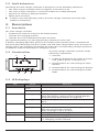
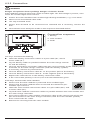
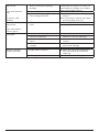
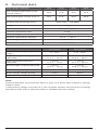
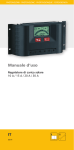
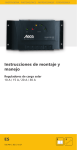
PHOTOVOLTAIK - PHOTOVOLTAICS - PHOTOVOLTAIQUE - FOTOVOLTAICA Installation and operating instructions Solar charge controller 10 A / 15 A / 0 A / 30 A EN 74.86 | Z0 | 10.7 1. About this manual These operating instructions are part of the product. Read these operating instructions carefully before use, keep them over the entire lifetime of the product, and pass them on to any future owner or user of this product. 1.1 Applicability This manual describes the installation, function, operation and maintenance of the solar charge controller. Further technical information is provided in a separate technical manual. 1.2 Users These operating instructions are intended for end customers. A technical expert must be consulted in cases of uncertainty. 1.3.Description of symbols Safety instructions are identified as follows: SIGNAL WORD Type, source and consequences of the danger! Measures for avoiding danger Instructions relating to the functional safety of the system are in bold type. 2. Safety 2.1 Proper usage The solar charge controller may only be used in PV systems for charging and controlling lead-acid batteries in accordance with this operating manual and the charging specifications of the battery manufacturer. 2.2 Improper usage No energy source other than a solar generator may be connected to the solar charge controller. No mains devices, diesel generators or wind generators may be connected. Do not connect any defective or damaged measuring equipment. 2.3 General safety instructions Follow the general and national safety and accident prevention regulations. Never alter or remove the factory plates and identification labels. Keep children away from PV systems. Never open the device. 2.4 Other risks Danger of fire and explosion Do not use the solar charge controller in dusty environments, in the vicinity of solvents or where inflammable gases and vapours can occur. No open fires, flames or sparks in the vicinity of the batteries. Ensure that the room is adequately ventilated. Check the charging process regularly. Follow the charging instructions of the battery manufacturer. Battery acid Acid splashes on skin or clothing should be immediately treated with soap suds and rinsed with plenty of water. If acid splashes into the eyes, immediately rinse with plenty of water. Seek medical advice. 2.5 Fault behaviour Operating the solar charge controller is dangerous in the following situations: • • • • The solar charge controller does not appear to function at all. The solar charge controller or connected cables are visibly damaged. Emission of smoke or fluid penetration. When parts are loose. In these cases immediately remove the solar charge controller from the solar modules and battery. 3. Description 3.1 Functions The solar charge controller • monitors the state of charge of the battery bank, • controls the charging process, • controls the connection/disconnection of loads. This optimises battery use and significantly extends its service life. A battery charging algorithm protects the battery from harmful states. Activation of the three deep discharge functions (LVW, LVD and LVR) is dependent upon the state of charge (SOC). The switching thresholds lie within the corresponding voltage window in accordance with the discharge or charging current. 3.2 Construction 1 The solar charge controller consists of the following components: 2 1. info LED . 4 LEDs for displaying the state of charge (red, yellow, green 1 and green 2) 3. terminal block for connecting the solar module 4. terminal block for connecting the battery 3 4 5 5. terminal block for connecting the loads loads 3.3 LED displays LED Status Meaning Info LED illuminates green flashes red Red LED flashing quickly battery empty, state of charge < 40 % when the battery continues to be discharged the deep-discharge deactivation is triggered flashing deep-discharge deactivation, state of charge < 30 % illuminates battery weak, state of charge < 50 % Yellow LED normal operation a fault exists (see "Faults and remedies") flashing 1. green LED 2. green LED switch-on threshold after deep-discharge deactivation has not yet been reached, state of charge is 40 % to 50 % illuminates battery good, state of charge > 50 % illuminates battery full, state of charge > 80 % flashing quickly battery full, charge regulation active, i.e. charging current reduced 4. Installation WARNING Danger of explosion from sparking! Danger of electric shock! The solar charge controller may only be connected to the local loads and the battery by trained personnel and in accordance with the applicable regulations. Follow the installation and operating instructions for all components of the PV system. Ensure that no cables are damaged. 4.1 Mounting the solar charge controller 4.1.1 Mounting location requirements • Do not mount the solar charge controller outdoors or in wet rooms. • Do not subject the solar charge controller to direct sunshine or other sources of heat. • Protect the solar charge controller from dirt and moisture. • Mount upright on the wall (concrete) on a non-flammable substrate. • Maintain a minimum clearance of 10 cm below and around the device to ensure unhindered air circulation. • Mount the solar charge controller as close as possible to the batteries (with a safety clearance of at least 30 cm). 4.1.2 Fastening the solar charge controller Mark the position of the solar charge controller fastening holes on the wall. Drill 4 Ø 6 mm holes and insert dowels. Fasten the solar charge controller to the wall with the cable openings facing downwards, using 4 oval head screws M4x40 (DIN 7996). 4.2 Connection 4.2.1 Preparing the wiring The cross section of the connection cable depends on the power output of the solar charge controller. Controller type 10 A 15 A 20 A 30 A Load/module current 10 A 15 A 20 A 30 A Cross-section AWG Insulation 6 mm2 10 mm2 10 mm2 16 mm2 10 8 8 6 85 °C 85 °C 85 °C 85 °C The table above applies to the following cable lengths: • 10 m solar module connection cable • 2 m battery connection cable • 5 m load connection cable Consult a dealer if the specified cable lengths are inadequate. An additional external fuse (not provided) must be connected to the battery connection cable, close to the battery pole. The external fuse prevents cable short circuits. A 40 A fuse can be used for all controller types. 4.2.2 Connection WARNING Danger of explosion from sparking! Danger of electric shock! Solar modules generate electricity under incident light. The full voltage is present, even when the incident light levels are low. Protect the solar modules from incident light during installation, e.g. cover them. Never touch uninsulated cable ends. Use only insulated tools. Ensure that all loads to be connected are switched off. If necessary, remove the fuse. Connections must always be made in the sequence described below. Connection sequence 1. battery 2. solar module 3. loads 2 1 3 1st step: Connect the battery Label the battery connection cables as a plus cable (A+) and a minus cable (A–). Lay the battery cables in parallel between the solar charge controller and the battery. Connect the battery connection cable with the correct polarity to the middle pair of terminals on the solar charge controller (with the battery symbol). If necessary, remove any external fuse. Connect battery connection cable A+ to the positive pole of the battery. Connect battery connection cable A– to the negative pole of the battery. Replace the external fuse in the battery connection cable. If the connection polarity is correct, the info LED illuminates green. 2nd step: Connect the solar module Ensure that the solar module is protected from incident light. Ensure that the solar module does not exceed the maximum permissible input current. Label the solar module connection cables as a plus cable (M+) and a minus cable (M–). Lay both solar module connection cables in parallel between the solar module and the solar charge controller. First connect the M+ solar module connection cable to the correct pole of the left pair of terminals on the solar charge controller (with the solar module symbol), then connect the M– cable. Remove the covering from the solar module. 3rd step: Connect loads Notes • Connect loads that must not be deactivated by the solar charge controller deep discharge protection, e.g. emergency lights or radio connection, directly to the battery. • Loads with a higher current consumption than the device output can be directly connected to the battery. However, the solar charge controller deep discharge protection will no longer intervene. Loads connected in this manner must also be separately fused. Label the load connection cables as a plus cable (L+) and a minus cable (L–). Lay the load connection cables in parallel between the solar charge controller and the load First connect the L+ load cable to the correct pole of the right pair of terminals on the solar charge controller (with the lamp symbol), then connect the L– cable. Replace the load fuse or switch on the load. 4th step: Final work Fasten all cables with strain relief in the direct vicinity of the solar charge controller (clearance of approx. 10 cm). 4.2.3 Grounding The components in stand-alone systems do not have to be grounded – this is not standard practice or may be prohibited by national regulations (e.g.: DIN 57100 Part 410: Prohibition of grounding protective low voltage circuits). Consult the technical manual for more information. 4.2.4 Lightning protection In systems subjected to an increased risk of overvoltage damage, we recommend installing additional lightning protection / overvoltage protection to reduce dropouts. Consult the technical manual for more detailed information. 5. Operation The solar charge controller immediately begins operation once the battery is connected or the external fuse is inserted. The displays of the solar charge controller show the current operating mode. User intervention or user settings are not required. Protection functions The following integrated protection functions of the solar charge controller ensure that the battery is handled as gently as possible. The following protection functions are part of the basic function of the controller: • Overcharge protection • Deep discharge protection • Battery undervoltage protection • Solar module reverse current protection The following installation faults do not destroy the controller. After correcting the fault, the device will continue to operate correctly: • • • • • • • Protection from solar module short circuits / incorrect solar module polarity Protection from short circuits at the load output or excessive load current Protection from battery connection with incorrect polarity Protection from solar module overcurrent Protection from device overtemperature Protection from overvoltage at the load output Protection from the wrong connection sequence 6. Maintenance The solar charge controller is maintenance-free. All components of the PV system must be checked at least annually, according to the specifications of the respective manufacturers. Ensure adequate ventilation of the cooling element. Check the cable strain relief. Check that all cable connections are secure. Tighten screws if necessary. Terminal corrosion 7. Faults and remedies Fault No display Cause Remedy • battery voltage too low • the external fuse in the battery connection cable has blown. • battery is not connected • battery is connected with the wrong polarity • battery is defective pre-charge replace the battery the external fuse 1. unclamp all connections . connect a (new) battery with the correct polarity Load cannot be op- • load output is switched off erated or only for a due to excessive load current short time 3. reconnect the solar module and loads charging automatically continues as soon as the charging current lies within the permissible range reduce load current, if necessary switch off or disconnect loads + check Info LED flashes red info LED flashes red • charging interrupted due to excessive charging current • load output is switched off due to short circuit at load output • load output is switched off due to overheating of the solar charge controller loads 1. disconnect loads . correct the cause of the short circuit 3. reconnect loads the load output automatically switches on again once the solar charge controller has cooled down improve the cooling air circulation remove sources any other heat check Load cannot be operated + • load output is switched off due to too low battery voltage info LED flashes red the conditions of use and the mounting location the load output automatically switched on again as soon as the battery voltage lies within the permissible range pre-charge the battery equip loads directly connected to the battery with deep discharge protection + red battery LED flashes check the battery and replace if necessary Load cannot be operated + info LED flashes red + • load output is switched off due to excessive battery voltage • incorrect grounding • external charging source is not voltage-limited 2. green LED flashes Load cannot be operated the load output automatically switched on again as soon as the battery voltage lies within the permissible range check the grounding check the external charging source if • defective load or installation error necessary, switch off external charging sources connect load correctly replace load + info LED illuminates green Battery is not charged Battery display jumps quickly • solar module not connected • solar module connected with incorrect polarity • short circuit at solar module input • incorrect solar module voltage • solar module defective • large pulse current • battery is defective connect the solar module the solar module with the correct polarity correct the cause of the short circuit use a solar module of the specified voltage replace the solar module tune the current consumption to match the battery capacity replace the battery connect 8. Technical data Solar charge controller 10 A 15 A 20 A 30 A Max. module input short circuit current at 50 °C 10 A 15 A 20 A 30 A Max. load output current at 50 °C 10 A 15 A 20 A 30 A Terminal size (fine/single wire) 16/25 mm² = 6/4 AWG Weight 345 g Dimensions l x w x h 187 x 96 x 45 mm Enclosure protection class IP 32 System voltage 12 V / 24 V Ambient temperature allowed –25 °C ... +50 °C Max. voltage of Solar collector 47 V DC Temperature compensation –4 mV/K/Zelle 12-V-system 24-V-system Permissible battery voltage range * 9 - 17 V 17,1 - 34 V Deep discharge warning (SOC/LVW) < 40 % / 11,7 V ~ 12,3 V < 40 % / 23,4 V ~ 24,6 V Deep discharge protection (SOC/LVD) < 30 % / 11,2 V ~ 11,6 V < 30 % / 22,1 V ~ 23,2 V Reconnection set point (SOC/LVR) > 50 % / 12,4 V ~ 12,7 V > 50 % / 24,8 V ~ 25,4 V End of charge voltage (float) 13,9 V 27,8 V Boost charge voltage (boost) 14,4 V 28,8 V Equalisation charge (equal) 14,7 V 29,4 V NOTE: Technical data that varies from the above is given on a device label. Subject to change without notice. *If the battery voltage is less than 9 V, the controller switches off and cannot recharge the battery itself, even if sufficient power is available from the module. 9. Legal guarantee According to the German legal requirements, for this product the customer has a 2 year legal guarantee. The seller will remove all manufacturing and material faults that occur in the product during the legal guarantee period and affect the correct functioning of the product. Natural wear and tear does not constitute a malfunction. Legal guarantee does not apply if the fault can be attributed to third parties, unprofessional installation or commissioning, incorrect or negligent handling, improper transport, excessive loading, use of improper equipment, faulty construction work, unsuitable construction location or improper operation or use. Legal guarantee claims shall only be accepted if notification of the fault is provided immediately after it is discovered Legal guarantee claims are to be directed to the seller. The seller must be informed before legal guarantee claims are processed. For processing a legal guarantee claim an exact fault description and the invoice / delivery note must be provided. The seller can choose to fulfil the legal guarantee either by repair or replacement. If the product can neither be repaired nor replaced, or if this does not occur within a suitable period in spite of the specification of an extension period in writing by the customer, the reduction in value caused by the fault shall be replaced, or, if this is not sufficient taking the interests of the end customer into consideration, the contract is cancelled. Any further claims against the seller based on this legal guarantee obligation, in particular claims for damages due to lost profit, loss-of-use or indirect damages are excluded, unless liability is obligatory by German law. 10