1
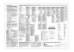
Page 1 of 7
Installation
instructions
Active wall mounting:
Protector ST-01 ®
The Protector ST-01 ® is to be mounted at the site of installation (concrete, brick, wood and plasterboard walls,
etc.) in accordance with the following instructions.
The mounting height may vary depending upon the applicable local or national regulations (for example: building
codes, fire protection regulations, etc.).
A. Preparation prior to installation
Prior to installation, insert the battery recommended by the manufacturer (not included) into the
Protector ST-01 ® battery case and connect to the terminal pad taking care to ensure correct polarity.
If additional modules (e.g. radio module, etc.) are to be used, connect them to the power supply prior to
installing the Protector ST-01 ®.
Please be aware that a fire extinguisher should not be placed in the Protector ST-01 ® before the
Protector ST-01 ® has been properly fitted at the site of installation using correctly dimensioned screws
and wall plugs. Doing so risks breaking the sprung suspension system.
B. Installation
The Protector ST-01 ® is mounted at the site of installation with the open side facing the wall. A barrier
between the Protector ST-01 ® and the wall is not required.
It should be noted that the screws and dowels used must be suitable for the material at the site of installation.
The following screws and dowels are recommended by the manufacturer for concrete and brick walls:
Universal or wood screws: Dowels:
5,0 * 70,00 mm
Fischer UX 8 * 50 R (suitable for all building materials)
For secure installation 5 screws and 5 dowels must be used (not included).
It is essential to make sure that the centre screw (adjustment screw) is only tightened to the extent that
the bracket attachment still has unhindered movement. After tightening the centre screw please check that the
bracket attachment can still move freely.
®
Page 2 of 7
Installation
instructions
Active wall mounting:
Protector ST-01 ®
C. Tasks after installation
After installation proceed as follows:
Place the fire extinguisher on the Protector ST-01 ®.
Once the fire extinguisher is mounted, follow the instructions shown in section C in the user manual concerning
entering an access code. Attention: pay specific attention to the blue flashing signal when implementing the
coding (the audible signal is generated for technical reasons only and is irrelevant for the coding)!
When using a personal access code, make sure that this code is noted and stored by the person responsible for
the Protector ST-01 ®. If the personal access code is lost, it can only be reset using the manufacturer’s master
code. A personal code is not recommended if the Protector ST-01 ® is used in a private home.
After entering the access code a test of all the Protector ST-01 ® functions must be performed by following
the steps below:
1. Fire extinguisher removal test
no
Audible signal
yes (= ok)
a) Check battery (Voltage and/or polarity check)
b) Check the limit switch with the fire extinguisher
in place (Bracket attachment must depress the
limit switch)
c) Contact the manufacturer
yes (= ok)
no
Optical signal – yellow LED
a) Contact the manufacturer
2. Setting the volume
The volume can be adjusted to suit the ambient environment (see section C in the user manual).
®
Page 3 of 7
Installation
instructions
Active wall mounting:
Protector ST-01 ®
3. Fire simulation test (in conjunction with wireless smoke detectors and radio module)
If the Protector ST-01 ® (loaded with the fire extinguisher) is operated in conjunction with a branded
wireless smoke detector and the corresponding radio module, then is possible to simulate the outbreak of
fire as described below.
Activation of the branded wireless smoke detector using a test aerosol or the test button should trigger the
Protector ST-01 ® to emit the following signals:
no
Audible signal
yes (= ok)
a) Check the radio connection between the smoke
detector and the Protector (triggering distance
approximately 2 m apart)
b) Battery check (same as 1 above)
c) Check the correctness of the coding between
the smoke detector and the radio module
d) Check using replacement units
(smoke detector and radio module)
e) Contact the manufacturer
Optical signal – green LED
yes (= ok)
no
If several Protector ST-01 ® devices are operated with radio modules, and if one of the fire extinguishers is
removed from one of the Protector ST-01 ® devices following the fire alarm, then both signals are terminated
for that particular Protector ST-01 ®, whereas the signals on all of the other Protector ST-01 ® devices
remain functional. In the event of fire this ensures that the nearest working fire extinguisher is always indicated.
®
Page 4 of 7
User manual
Active wall mounting:
Protector ST-01 ®
A. Extinguisher fill level
The basic version of the Protector ST-01 ® is designed for one full 6 kg (6 litres) fire extinguisher.
Please note that when using a 12 kg (12 litres) fire extinguisher the audible and visual alarms are only triggered
when the extinguisher if completely empty. Indication of partial filling level can be facilitated at any time by fitting
the correct 12 kg conversion spring.
In case of fire or theft the visual and audible alarm is not affected.
B. Maintenance
The Protector ST-01 ® has a 2-year maintenance interval. The due date is indicated after 26 months by a blue
flashing light. As part of the maintenance service the battery must be replaced with a battery recommended by
the manufacture (letter E in the user manual) and the device must be checked to ensure a trouble-free, functional
condition. Resetting the service indicator is described in the following paragraph „Programming“ (Section C of
the user manual).
C. Programming
The Protector ST-01 ® can be programmed from the front of the casing without opening the device, using a
permanent magnet. By assigning a personal access code this programming function can be blocked to prevent
unauthorized use.
Programming is performed by applying a permanent magnet to the right edge of the device. When a magnet is
close to the device a blue flashing signal with a cadence of approximately 0.6 seconds is triggered. Attention: pay
specific attention to the blue flashing signal when implementing the coding (the audible signal is generated
for technical reasons only and is irrelevant for the coding)!
All functions are assigned three-digit codes. The input is performed by repeated application of the magnet until
the number of flashes corresponding to the respective code number is called-up. After entering a code number the
magnet must be removed from the device for at least one flash interval (0.6 seconds) before the next code position
is accessed.
®
Page 5 of 7
User manual
Active wall mounting:
Protector ST-01 ®
The device acknowledges the entry of a valid three-digit code with four green flashes and a beep. An invalid code
is indicated by four yellow flashes and four short beeps.
After the entry or deletion of a personal access code, the entry will be acknowledged after six positions have been
entered. The integers 1 to 9 are valid for the access code.
If a personal access code has been set, then it must be entered before programming can begin. After setting or
correctly entering a personal access code the device remains unlocked for a period of ten minutes before automatically locking itself again. The personal code is securely stored and retained even after the battery has been
removed.
Local alarm functions (LED and beep) and relay output (normally closed and break contact) can be activated and
deactivated independently of each other. If the alarm is activated for longer than 1 minute, the relay is automatically reset. In such cases the alarm is immediately available again for new alarm activation.
The functions have been assigned the following codes:
• Switching on the Alarm Function
1–2–3
• Switching off the Alarm Function
3–2–1
• Activating the Relay Output 1–2–4
• Deactivating the Relay Output 4–2–1
• Resetting the maintenance interval
4–3–2
• Three-stage settings for the audible alarm
loud
quiet
off
2–3–3
2–2–2
2–1–1
• Setting a personal access code
4–6–8–x–y–z
• Deletion of a personal access code
4 – 6 – 8 – 10 – 10 – 10
• To unlock the programming function if the personal access code has been lost,
contact the manufacturer for the master code.
®
Page 6 of 7
User manual
Active wall mounting:
Protector ST-01 ®
D. Inputs and outputs
The Protector ST-01 ® has two terminal blocks with contacts numbered 1 to 6 and 7 to 12
(see terminal schematic diagram).
12
contact switch port / access
11
port / access for external alarm voltage
10
9
break contact port / access
8
7
alarm ports 5, 6, 7
K1
6
5
4
removal protection switch
3
2
9 Volt battery
1
Contacts 1 / 2 and 3 / 4 are used to connect the 9-volt battery and the micro switch for tamper-proofing and fill-level
monitoring. They are pre-wired when the unit is delivered.
D.1. Alarm outputs
Contacts 5, 6 and 7 are connected to an internal transfer relay, which is activated in the case of an alarm.
D.2. Alarm inputs
Contacts 8 to 12 are inputs for external alarm signals.
Contacts 8 and 9 can be used for a break contact. If these terminals are not used, they must be bridged.
The devices are already bridged on delivery.
An external alarm DC voltage can be added between terminals 10 and 11. The positive terminal must be
connected to terminal 11.
Contacts 11 and 12 allow the connection of an external contact switch.
®
Page 7 of 7
User manual
Active wall mounting:
Protector ST-01 ®
E. Power supply
9 V Alkaline battery, minimum capacity 600 mAh
Battery service life > 2 years
Maintenance interval 2 years + 2 months grace period
Overdue maintenance is indicated by a flashing blue LED.
Battery status is monitored. If the voltage falls below the minimum requirement, it is indicated by a faint beep
every minute over a period of 30 days.
F. Ambient conditions
Working temperature
-10 to +55 °C (limited by the battery)
Storage temperature
-25 to +85 °C
Humidity
< 90 %, non-condensing
®